EP0165655A1 - Système de commande de l'échappement pour moteurs à deux temps - Google Patents
Système de commande de l'échappement pour moteurs à deux temps Download PDFInfo
- Publication number
- EP0165655A1 EP0165655A1 EP85301930A EP85301930A EP0165655A1 EP 0165655 A1 EP0165655 A1 EP 0165655A1 EP 85301930 A EP85301930 A EP 85301930A EP 85301930 A EP85301930 A EP 85301930A EP 0165655 A1 EP0165655 A1 EP 0165655A1
- Authority
- EP
- European Patent Office
- Prior art keywords
- exhaust passage
- engine
- auxiliary
- cylinder
- main exhaust
- Prior art date
- Legal status (The legal status is an assumption and is not a legal conclusion. Google has not performed a legal analysis and makes no representation as to the accuracy of the status listed.)
- Granted
Links
Images


Classifications
-
- F—MECHANICAL ENGINEERING; LIGHTING; HEATING; WEAPONS; BLASTING
- F02—COMBUSTION ENGINES; HOT-GAS OR COMBUSTION-PRODUCT ENGINE PLANTS
- F02D—CONTROLLING COMBUSTION ENGINES
- F02D13/00—Controlling the engine output power by varying inlet or exhaust valve operating characteristics, e.g. timing
- F02D13/02—Controlling the engine output power by varying inlet or exhaust valve operating characteristics, e.g. timing during engine operation
- F02D13/028—Controlling the engine output power by varying inlet or exhaust valve operating characteristics, e.g. timing during engine operation for two-stroke engines
- F02D13/0284—Variable control of exhaust valves only
-
- F—MECHANICAL ENGINEERING; LIGHTING; HEATING; WEAPONS; BLASTING
- F02—COMBUSTION ENGINES; HOT-GAS OR COMBUSTION-PRODUCT ENGINE PLANTS
- F02B—INTERNAL-COMBUSTION PISTON ENGINES; COMBUSTION ENGINES IN GENERAL
- F02B33/00—Engines characterised by provision of pumps for charging or scavenging
- F02B33/02—Engines with reciprocating-piston pumps; Engines with crankcase pumps
- F02B33/28—Component parts, details or accessories of crankcase pumps, not provided for in, or of interest apart from, subgroups F02B33/02 - F02B33/26
- F02B33/30—Control of inlet or outlet ports
-
- F—MECHANICAL ENGINEERING; LIGHTING; HEATING; WEAPONS; BLASTING
- F02—COMBUSTION ENGINES; HOT-GAS OR COMBUSTION-PRODUCT ENGINE PLANTS
- F02D—CONTROLLING COMBUSTION ENGINES
- F02D9/00—Controlling engines by throttling air or fuel-and-air induction conduits or exhaust conduits
- F02D9/04—Controlling engines by throttling air or fuel-and-air induction conduits or exhaust conduits concerning exhaust conduits
-
- F—MECHANICAL ENGINEERING; LIGHTING; HEATING; WEAPONS; BLASTING
- F02—COMBUSTION ENGINES; HOT-GAS OR COMBUSTION-PRODUCT ENGINE PLANTS
- F02B—INTERNAL-COMBUSTION PISTON ENGINES; COMBUSTION ENGINES IN GENERAL
- F02B75/00—Other engines
- F02B75/02—Engines characterised by their cycles, e.g. six-stroke
- F02B2075/022—Engines characterised by their cycles, e.g. six-stroke having less than six strokes per cycle
- F02B2075/025—Engines characterised by their cycles, e.g. six-stroke having less than six strokes per cycle two
-
- Y—GENERAL TAGGING OF NEW TECHNOLOGICAL DEVELOPMENTS; GENERAL TAGGING OF CROSS-SECTIONAL TECHNOLOGIES SPANNING OVER SEVERAL SECTIONS OF THE IPC; TECHNICAL SUBJECTS COVERED BY FORMER USPC CROSS-REFERENCE ART COLLECTIONS [XRACs] AND DIGESTS
- Y02—TECHNOLOGIES OR APPLICATIONS FOR MITIGATION OR ADAPTATION AGAINST CLIMATE CHANGE
- Y02T—CLIMATE CHANGE MITIGATION TECHNOLOGIES RELATED TO TRANSPORTATION
- Y02T10/00—Road transport of goods or passengers
- Y02T10/10—Internal combustion engine [ICE] based vehicles
- Y02T10/12—Improving ICE efficiencies
Definitions
- This invention relates to an exhaust control system for a two-cycle engine mounted to a motorcycle, etc.
- Fig. 8 shows an exhaust control system of the prior art for a two-cycle engine comprising a main exhaust passage 1, an auxiliary exhaust passage 2 and a rotary valve 3 having a shaft disposed normal to a center line O of a cylinder of the engine.
- the rotary valve 3 is operative to open and close the auxiliary exhaust passage 2 with respect to the main exhaust passage 1. More specifically, the rotary valve 3 operates such that it successively opens the auxiliary exhaust passage 2 with respect to the main exhaust passage 1 as the engine speed increases so as to provide an improved output power of the engine in a high engine speed range by causing the cross-sectional area of an exhaust of the engine to match the engine characteristic in the high engine speed range.
- the invention has been developed for the purpose of obviating the aforesaid disadvantages of the prior art. Accordingly, the invention has as its object the provision of an exhaust control system for a two-cycle engine capable of providing an improved output power of the engine in a high engine speed range while enabling rotary valves for opening and closing auxiliary exhaust passages to have an opening of an area large enough to perform an auxiliary exhaust passage opening and closing operation satisfactorily.
- At least one auxiliary exhaust passage is formed at one side of a main exhaust passage circumferentially of a cylinder of the engine, and at least one rotary valve for adjustably opening and closing the auxiliary exhaust passage which is in the form of a shaft parallel to a center line of the cylinder is rotatably mounted between the main exhaust passage and the auxiliary exhaust passage.
- the rotary valve operates such that it closes the auxiliary- exhaust passage with respect to the main exhaust passage when the engine is in a low engine speed range and it successively opens the auxiliary exhaust passage with respect to the main exhaust passage as the engine speed increases, to thereby cause the cross-sectional area of an exhaust to match the engine characteristic in a high engine speed range.
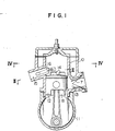
- a cylinder 10 has a piston 12 slidably fitted therein, and is formed with a suction passage 13, a scavenging passage 14 and a main exhaust passage 15.
- the suction passage 13 is provided with a reed valve 7 and opened and closed by the piston 12 as the latter moves in vertical sliding movement with respect to a crank chamber 8 enclosed by a crank case 11.
- the scavenging passage 13 opens at its lower end in the crank chamber 8 and has its upper end opened and closed with respect to the cylinder 10 by the piston 12 as the latter moves in vertical sliding movement.
- a first auxiliary exhaust passage 16 and a second auxiliary exhaust passage 17 are located at opposite sides of the main exhaust passage 15 circumferentially of the cylinder 10.
- the first and second auxiliary exhaust passages 16 and 17 independently open at one end thereof in the cylinder 10, and a first rotary valve 18 and a second rotary valve 19 for adjustably opening and closing the first auxiliary exhaust passage 16 and second auxiliary passage 17, respectively, at an opposite end thereof, are mounted to bring the auxiliary exhaust passages 16 and 17 into and out of communication with the main exhaust passage 15 in an intermediate portion of the latter.
- the two rotary valves 18 and 19 are each in the form of a shaft located parallel to the center line O of the cylinder 10 and supported by a respective valve boss 25 of the cylinder 10 for rotation.
- the rotary valves 18 and 19 are formed with cutout passages 26 and 27, respectively.
- the rotary valves 18 and 19 are located at one side of a rack shaft 28 and have pinions 31 and 32 attached thereto, respectively, to provide two unitary structures.
- the pinions 31 and 32 are maintained in meshing engagement with serrations 33 and 34, respectively,_of the rack shaft 28 which is supported by bosses 35 for movement in an axial direction and extends into a transmission chamber 36.
- a portion of the rack shaft 28 extending into the transmission chamber 36 has a pair of adjusting plates 37, and a vertical pin 39 of a pivotal arm 38 extends between the two adjusting plates 37 into engagement therewith.
- the pivotal arm 38 is secured to'a vertical rotary shaft 40.
- the rotary shaft 40 has secured to a lower end portion thereof an arm 42 having a vertical pin 41 which is held between a pair of annular adjusting plates 44 of a slider 43.
- the slider 43 which is fitted over a governor rotary shaft 45 for axial sliding movement causes, as it moves axially in sliding movement, the rotary shaft 40 to rotate via the plates 44, pin 41 and arm 42.
- governor means 30 comprises a pair of dish-shaped concave-surface plates 46 and 47, a plurality of centrifugal balls 48 held between the two dish-shaped concave-surface plates 46 and 47 and a governor spring 49 to constitute what is usually referred to as centrifugal ball type governor means.
- the concave-surface plate 47 is formed integrally with the slider 43 described hereinabove.
- the governor spring 49 which is mounted in compressed condition between the adjusting plate 44 and a governor drive gear 51 biases the concave-surface plate 47 in a direction opposite the direction indicated by an arrow E via the adjusting plate 44.
- the governor drive gear 51 is secured to the governor rotary shaft 45 journalled by a bearing 57 and meshes with a crank gear 56 of a crankshaft 55.
- a boss member 58 supports the vertical rotary shaft 40 for rotation.
- the cross-sectional area of an exhaust from the cylinder 10 which is equal to the cross-sectional area of the main exhaust passage 15 when the engine operates in a low engine speed range gradually increases as the cross-sectional areas of open portions of the two auxiliary exhaust passages 16 and 17 increase, until the cross-sectional area of the exhaust becomes equal to the cross-sectional area of the main exhaust passage 15 plus the cross-sectional areas of the two auxiliary exhaust passages 16 and 17 and matches the characteristics of the engine operating in a high engine speed range. This is conducive to improved output power of the engine.
- the two auxiliary exhaust passages 16 and 17 are fully open with respect to the main exhaust passage 15 as shown in Fig. 3, with a result that the cross-sectional area of an exhaust emission from the cylinder 10 which becomes equal to the cross-sectional area of the main exhaust passage 15 plus the cross-sectional areas of the two auxiliary exhaust passages 16 and 17 is maximized and matches the characteristic of the engine overrunning or operating at the highest engine speed.
- control of the exhaust performed by the exhaust emission control system according to the invention achieves excellent effects in increasing the output power of the engine.
- a second embodiment shown in Fig. 6 in which an expansion chamber 21 is communicated with a first expansion passage 23 and a second expansion passage 24 of the cylinder 10 which in turn are communicated with the main exhaust passage 15 through the rotary valves 18 and 19 which can be opened and closed.
- the valves 18 and 19 are located on opposite sides of the rack shaft 28.
- the first rotary valve 18 rotates in the direction indicated by the arrow A while the second rotary valve 19 rotates in the direction indicated by the arrow A'.
- the auxiliary exhaust passages 16 and 17 are closed with respect to the main exhaust passage 15 while the expansion chamber 21 is opened to communicate with the main exhaust passage 15 as shown in Fig. 6.
- the expansion chamber 21 is fully open with respect to the main exhaust passage 15 via the passages 23 and 24 when the engine operates in a low engine speed range. This makes it possible to absorb pulsations occurring in exhaust passages, thereby improving the output power of the engine in the low engine speed range.
- the expansion chamber 21 is successively closed as the rpm. of the engine increases, but the pulsations in the exhaust passages are gradually reduced with an increase in the rpm. of the engine. Thus, an increase in the pulsation can be avoided.
- the system has been shown and described as having two auxiliary exhaust passages.
- the invention is not limited to this specific number of the auxiliary exhaust passages and the number of the auxiliary exhaust passages may be one or three or more.
- the number of the rotary valves should also be altered to correspond to the number of the auxiliary exhaust passages.
- the invention can achieve the following effects.
- the auxiliary exhaust passages remain closed, so that the exhaust has a small cross-sectional area.
- the auxiliary exhaust passages are gradually opened and the cross-sectional area of the exhaust successively increases until the cross-sectional area of the exhaust is maximized when the two auxiliary exhaust passages are both fully open as the engine overruns or its speed reaches a highest level.
- the characteristic of the engine is substantially stabilized and the output power of the engine is markedly improved particularly because of the fact that effective use can be made of the auxiliary exhaust passages in the engine high speed range.
- the rotary valves for opening and closing the auxiliary exhaust passages with respect to the main exhaust passage are each in the form of a shaft and located in parallel to the center line of the cylinder of the engine.
- This arrangement enables the area of the opening of each of the rotary valves to be increased with ease as compared with the arrangement of the rotary valve in the prior art shown in Fig. 8 whereby the rotary valve is located normal to the center line of the cylinder in a position above the main exhaust passage.
- no difficulties are experienced in increasing the diameter of the rotary valves and the axial length of the cutout passages of the valves to increase the area of the opening of each of the rotary valves.
- An increase in the area of the opening of each rotary valve is conducive to increased efficiency in the use of auxiliary exhaust passages.
- the auxiliary exhaust passages are located at opposite sides of the main exhaust passage circumferentially of the cylinder. This arrangement prevents the occurrence of a change in the compression ratio of a fuel-air mixture in the cylinder which might otherwise occur when the auxiliary exhaust passages are opened.
- the compression ratio can be kept at a high level even when the engine operates in a high engine speed range, thereby increasing the characteristic of the engine in the high engine speed range.
Landscapes
- Engineering & Computer Science (AREA)
- Chemical & Material Sciences (AREA)
- Combustion & Propulsion (AREA)
- Mechanical Engineering (AREA)
- General Engineering & Computer Science (AREA)
- Characterised By The Charging Evacuation (AREA)
- Exhaust Silencers (AREA)
Applications Claiming Priority (2)
| Application Number | Priority Date | Filing Date | Title |
|---|---|---|---|
| JP104996/84 | 1984-05-23 | ||
| JP59104996A JPS60249614A (ja) | 1984-05-23 | 1984-05-23 | 2サイクルエンジンの排気孔制御装置 |
Publications (2)
| Publication Number | Publication Date |
|---|---|
| EP0165655A1 true EP0165655A1 (fr) | 1985-12-27 |
| EP0165655B1 EP0165655B1 (fr) | 1990-08-08 |
Family
ID=14395707
Family Applications (1)
| Application Number | Title | Priority Date | Filing Date |
|---|---|---|---|
| EP85301930A Expired - Lifetime EP0165655B1 (fr) | 1984-05-23 | 1985-03-20 | Système de commande de l'échappement pour moteurs à deux temps |
Country Status (4)
| Country | Link |
|---|---|
| US (1) | US4622928A (fr) |
| EP (1) | EP0165655B1 (fr) |
| JP (1) | JPS60249614A (fr) |
| DE (1) | DE3579054D1 (fr) |
Cited By (5)
| Publication number | Priority date | Publication date | Assignee | Title |
|---|---|---|---|---|
| GB2177755B (en) * | 1985-07-03 | 1989-07-12 | Piaggio & C Spa | Control of exhaust gas flow in two-stroke i.c. engines |
| EP0382063A1 (fr) * | 1989-02-06 | 1990-08-16 | Yamaha Hatsudoki Kabushiki Kaisha | Moteur à combustion interne à deux temps multicylindrique |
| US5832881A (en) * | 1995-06-29 | 1998-11-10 | Orbital Engine Company (Australia) Pty Limited | Supplementary port for two stroke engine |
| AT404392B (de) * | 1989-06-15 | 1998-11-25 | Avl Verbrennungskraft Messtech | Vorrichtung zur steuerung des auslasskanales einer zweitakt-brennkraftmaschine |
| DE19829430A1 (de) * | 1998-07-01 | 2000-01-05 | Horst Ruediger | Verbrennungsmotor, insbesondere Zweitakt-Dieselmotor |
Families Citing this family (18)
| Publication number | Priority date | Publication date | Assignee | Title |
|---|---|---|---|---|
| EP0210829B1 (fr) * | 1985-07-22 | 1989-11-02 | Honda Giken Kogyo Kabushiki Kaisha | Dispositif de commande du moment d'ouverture et de fermeture de l'échappement |
| DE3668348D1 (de) * | 1985-07-22 | 1990-02-22 | Honda Motor Co Ltd | Vorrichtung zur steuerung der auslasszeit einer brennkraftmaschine. |
| JPH0635832B2 (ja) * | 1985-09-11 | 1994-05-11 | 本田技研工業株式会社 | 2サイクルエンジンの排気時期制御装置 |
| JPS62174514A (ja) * | 1986-01-29 | 1987-07-31 | Honda Motor Co Ltd | 2サイクルエンジンの排気時期制御装置 |
| JPH065014B2 (ja) * | 1986-02-25 | 1994-01-19 | 川崎重工業株式会社 | 排気制御装置 |
| JPS62267515A (ja) * | 1986-05-14 | 1987-11-20 | Honda Motor Co Ltd | 2サイクルエンジンの排気時期制御装置 |
| US4776305A (en) * | 1986-05-20 | 1988-10-11 | Honda Giken Kogyo Kabushiki Kaisha | Exhaust timing control device for two-cycle engines |
| US4829945A (en) * | 1986-06-26 | 1989-05-16 | Honda Giken Kogyo Kabushiki Kaisha | Exhaust timing control device for two-cycle engines |
| JPS63272915A (ja) * | 1987-04-28 | 1988-11-10 | Kawasaki Heavy Ind Ltd | 2サイクルエンジンの排気制御方法 |
| US4766854A (en) * | 1987-06-19 | 1988-08-30 | Brunswick Corporation | Exhaust valve throttling mechanism for two-stroke engine |
| US4864980A (en) * | 1987-11-02 | 1989-09-12 | Brunswick Corporation | Exhaust valve throttling mechanism for two-stroke engine |
| JPH02204625A (ja) * | 1989-02-01 | 1990-08-14 | Yamaha Motor Co Ltd | 2サイクルエンジン |
| US5273004A (en) * | 1989-03-30 | 1993-12-28 | Institut Francais Du Petrole | Two-stroke engine with rotary valves and uses of such an engine |
| US4945868A (en) * | 1989-06-21 | 1990-08-07 | General Motors Corporation | Two cycle exhaust recycling |
| JPH055417A (ja) * | 1990-10-25 | 1993-01-14 | Yamaha Motor Co Ltd | 2サイクルデイーゼルエンジンの圧縮比可変装置 |
| US5628295A (en) * | 1996-04-15 | 1997-05-13 | Mcculloch Italiana Srl | Two-stroke internal combustion engine |
| US5967108A (en) * | 1996-09-11 | 1999-10-19 | Kutlucinar; Iskender | Rotary valve system |
| WO2006096850A2 (fr) * | 2005-03-09 | 2006-09-14 | Zajac Optimum Output Motors, Inc. | Moteur a combustion interne et procede associe |
Citations (3)
| Publication number | Priority date | Publication date | Assignee | Title |
|---|---|---|---|---|
| US1360061A (en) * | 1920-04-12 | 1920-11-23 | Jay G Wait | Rotary valve for internal-combustion engines |
| US4121552A (en) * | 1974-09-17 | 1978-10-24 | Yamaha Hatsudoki Kabushiki Kaisha | Exhaust means for two cycle engines |
| EP0145479A2 (fr) * | 1983-12-12 | 1985-06-19 | Kawasaki Jukogyo Kabushiki Kaisha | Système de commande de l'échappement pour moteurs 2 temps |
Family Cites Families (9)
| Publication number | Priority date | Publication date | Assignee | Title |
|---|---|---|---|---|
| US1154479A (en) * | 1912-05-14 | 1915-09-21 | George Burton Briney | Rotary valve for gas-engines. |
| US1174818A (en) * | 1914-07-03 | 1916-03-07 | Dean B Bubar | Rotary valve for explosive-engines. |
| US1179632A (en) * | 1915-06-10 | 1916-04-18 | Robert V Fessler | Internal-combustion engine. |
| US2008186A (en) * | 1930-12-20 | 1935-07-16 | Carl H Fink | Internal combustion engine |
| FR2250017A1 (en) * | 1973-11-07 | 1975-05-30 | Salzmann Willi | I.C. engine with single rotary valve - crankshaft drives rotary valve through spiral gear and upright shaft |
| JPS5139112U (fr) * | 1974-09-17 | 1976-03-24 | ||
| JPS5852510B2 (ja) * | 1976-04-27 | 1983-11-22 | 東芝テック株式会社 | 印字装置 |
| CS225088B1 (en) * | 1981-04-03 | 1984-02-13 | Jan Krivka | The exhaust of two-stroke internal combustion engine |
| DE3223636A1 (de) * | 1982-06-24 | 1983-12-29 | Siemens AG, 1000 Berlin und 8000 München | Ansteuerschaltung fuer piezowandler in tintenmosaikschreibeinrichtungen |
-
1984
- 1984-05-23 JP JP59104996A patent/JPS60249614A/ja active Granted
-
1985
- 1985-03-19 US US06/713,544 patent/US4622928A/en not_active Expired - Lifetime
- 1985-03-20 DE DE8585301930T patent/DE3579054D1/de not_active Expired - Lifetime
- 1985-03-20 EP EP85301930A patent/EP0165655B1/fr not_active Expired - Lifetime
Patent Citations (3)
| Publication number | Priority date | Publication date | Assignee | Title |
|---|---|---|---|---|
| US1360061A (en) * | 1920-04-12 | 1920-11-23 | Jay G Wait | Rotary valve for internal-combustion engines |
| US4121552A (en) * | 1974-09-17 | 1978-10-24 | Yamaha Hatsudoki Kabushiki Kaisha | Exhaust means for two cycle engines |
| EP0145479A2 (fr) * | 1983-12-12 | 1985-06-19 | Kawasaki Jukogyo Kabushiki Kaisha | Système de commande de l'échappement pour moteurs 2 temps |
Non-Patent Citations (1)
| Title |
|---|
| PATENTS ABSTRACTS OF JAPAN, vol. 8, no. 216 (M-329)[1653], 3rd October 1984; & JP - A - 59 101 534 (YAMAHA HATSUDOKI K.K.) 12-06-1984 * |
Cited By (5)
| Publication number | Priority date | Publication date | Assignee | Title |
|---|---|---|---|---|
| GB2177755B (en) * | 1985-07-03 | 1989-07-12 | Piaggio & C Spa | Control of exhaust gas flow in two-stroke i.c. engines |
| EP0382063A1 (fr) * | 1989-02-06 | 1990-08-16 | Yamaha Hatsudoki Kabushiki Kaisha | Moteur à combustion interne à deux temps multicylindrique |
| AT404392B (de) * | 1989-06-15 | 1998-11-25 | Avl Verbrennungskraft Messtech | Vorrichtung zur steuerung des auslasskanales einer zweitakt-brennkraftmaschine |
| US5832881A (en) * | 1995-06-29 | 1998-11-10 | Orbital Engine Company (Australia) Pty Limited | Supplementary port for two stroke engine |
| DE19829430A1 (de) * | 1998-07-01 | 2000-01-05 | Horst Ruediger | Verbrennungsmotor, insbesondere Zweitakt-Dieselmotor |
Also Published As
| Publication number | Publication date |
|---|---|
| US4622928A (en) | 1986-11-18 |
| JPS60249614A (ja) | 1985-12-10 |
| EP0165655B1 (fr) | 1990-08-08 |
| DE3579054D1 (de) | 1990-09-13 |
| JPH0255606B2 (fr) | 1990-11-27 |
Similar Documents
| Publication | Publication Date | Title |
|---|---|---|
| US4622928A (en) | Exhaust control system for two-cycle engine | |
| EP0413317B1 (fr) | Dispositif de commande des soupapes d'échappement pour un moteur à deux temps multicylindre parallèle | |
| US4426985A (en) | Supercharged internal combustion engine | |
| US5497735A (en) | Internal combustion engine for portable power generating equipment | |
| US4109634A (en) | Apparatus for modifying an internal combustion engine | |
| US4558566A (en) | Apparatus for controlling exhaust system of internal-combustion engine | |
| US5138839A (en) | Control system for internal combustion engine with turbo supercharger | |
| US4539951A (en) | Variable valve timing mechanism | |
| EP0745179B1 (fr) | Moteur a combustion interne dote d'un assemblage de tiroirs de rotation a calage de distribution variable | |
| US5063887A (en) | Exhaust control valve system for parallel multi-cylinder two-cycle engine | |
| US5220890A (en) | Variable compression device for two cycle diesel engine | |
| EP0141650A2 (fr) | Orifices d'échappement | |
| CA2422410C (fr) | Moteur a combustion avec taux de compression variable | |
| US4570439A (en) | Exhaust control system for 2-cycle engines | |
| US4528958A (en) | Intake control system of engine | |
| US4354459A (en) | Non-throttling control apparatus for spark ignition internal combustion engines | |
| US4422415A (en) | Intake system of engines | |
| US4864980A (en) | Exhaust valve throttling mechanism for two-stroke engine | |
| US4766854A (en) | Exhaust valve throttling mechanism for two-stroke engine | |
| EP0172688A1 (fr) | Moteur à deux temps | |
| EP0461587B1 (fr) | Cycle à moteur | |
| JPS58167822A (ja) | 4サイクル機関の過給装置 | |
| JPH0526926B2 (fr) | ||
| JP3483052B2 (ja) | 2サイクルエンジンの排気制御装置 | |
| JP2598420Y2 (ja) | 2サイクルエンジンの排気バルブ装置 |
Legal Events
| Date | Code | Title | Description |
|---|---|---|---|
| PUAI | Public reference made under article 153(3) epc to a published international application that has entered the european phase |
Free format text: ORIGINAL CODE: 0009012 |
|
| 17P | Request for examination filed |
Effective date: 19850402 |
|
| AK | Designated contracting states |
Designated state(s): DE FR GB IT |
|
| 17Q | First examination report despatched |
Effective date: 19861022 |
|
| GRAA | (expected) grant |
Free format text: ORIGINAL CODE: 0009210 |
|
| AK | Designated contracting states |
Kind code of ref document: B1 Designated state(s): DE FR GB IT |
|
| REF | Corresponds to: |
Ref document number: 3579054 Country of ref document: DE Date of ref document: 19900913 |
|
| ITF | It: translation for a ep patent filed | ||
| ET | Fr: translation filed | ||
| PLBE | No opposition filed within time limit |
Free format text: ORIGINAL CODE: 0009261 |
|
| STAA | Information on the status of an ep patent application or granted ep patent |
Free format text: STATUS: NO OPPOSITION FILED WITHIN TIME LIMIT |
|
| 26N | No opposition filed | ||
| ITTA | It: last paid annual fee | ||
| REG | Reference to a national code |
Ref country code: GB Ref legal event code: IF02 |
|
| PGFP | Annual fee paid to national office [announced via postgrant information from national office to epo] |
Ref country code: FR Payment date: 20020312 Year of fee payment: 18 |
|
| PGFP | Annual fee paid to national office [announced via postgrant information from national office to epo] |
Ref country code: GB Payment date: 20020320 Year of fee payment: 18 |
|
| PGFP | Annual fee paid to national office [announced via postgrant information from national office to epo] |
Ref country code: DE Payment date: 20020327 Year of fee payment: 18 |
|
| PG25 | Lapsed in a contracting state [announced via postgrant information from national office to epo] |
Ref country code: GB Free format text: LAPSE BECAUSE OF NON-PAYMENT OF DUE FEES Effective date: 20030320 |
|
| PG25 | Lapsed in a contracting state [announced via postgrant information from national office to epo] |
Ref country code: DE Free format text: LAPSE BECAUSE OF NON-PAYMENT OF DUE FEES Effective date: 20031001 |
|
| GBPC | Gb: european patent ceased through non-payment of renewal fee |
Effective date: 20030320 |
|
| PG25 | Lapsed in a contracting state [announced via postgrant information from national office to epo] |
Ref country code: FR Free format text: LAPSE BECAUSE OF NON-PAYMENT OF DUE FEES Effective date: 20031127 |
|
| REG | Reference to a national code |
Ref country code: FR Ref legal event code: ST |