EP0165697A1 - Dispositif de capteur optique - Google Patents
Dispositif de capteur optique Download PDFInfo
- Publication number
- EP0165697A1 EP0165697A1 EP19850303292 EP85303292A EP0165697A1 EP 0165697 A1 EP0165697 A1 EP 0165697A1 EP 19850303292 EP19850303292 EP 19850303292 EP 85303292 A EP85303292 A EP 85303292A EP 0165697 A1 EP0165697 A1 EP 0165697A1
- Authority
- EP
- European Patent Office
- Prior art keywords
- light
- low
- duty cycle
- pulse
- amplifier
- Prior art date
- Legal status (The legal status is an assumption and is not a legal conclusion. Google has not performed a legal analysis and makes no representation as to the accuracy of the status listed.)
- Granted
Links
- 230000003287 optical effect Effects 0.000 title claims abstract description 13
- 239000003990 capacitor Substances 0.000 claims description 21
- 238000000034 method Methods 0.000 claims description 8
- 238000005070 sampling Methods 0.000 claims description 6
- 239000000835 fiber Substances 0.000 abstract description 16
- 238000005452 bending Methods 0.000 abstract description 4
- 238000005259 measurement Methods 0.000 abstract description 2
- 238000010586 diagram Methods 0.000 description 2
- 230000000694 effects Effects 0.000 description 2
- 230000009471 action Effects 0.000 description 1
- 239000000872 buffer Substances 0.000 description 1
- 230000008859 change Effects 0.000 description 1
- 238000010276 construction Methods 0.000 description 1
- 230000008878 coupling Effects 0.000 description 1
- 238000010168 coupling process Methods 0.000 description 1
- 238000005859 coupling reaction Methods 0.000 description 1
- 230000005669 field effect Effects 0.000 description 1
- 238000001914 filtration Methods 0.000 description 1
- 230000007774 longterm Effects 0.000 description 1
- 238000004519 manufacturing process Methods 0.000 description 1
- 230000007246 mechanism Effects 0.000 description 1
- 239000013307 optical fiber Substances 0.000 description 1
- 230000008569 process Effects 0.000 description 1
- 230000001105 regulatory effect Effects 0.000 description 1
- 230000001960 triggered effect Effects 0.000 description 1
Images
Classifications
-
- G—PHYSICS
- G01—MEASURING; TESTING
- G01F—MEASURING VOLUME, VOLUME FLOW, MASS FLOW OR LIQUID LEVEL; METERING BY VOLUME
- G01F1/00—Measuring the volume flow or mass flow of fluid or fluent solid material wherein the fluid passes through a meter in a continuous flow
- G01F1/66—Measuring the volume flow or mass flow of fluid or fluent solid material wherein the fluid passes through a meter in a continuous flow by measuring frequency, phase shift or propagation time of electromagnetic or other waves, e.g. using ultrasonic flowmeters
-
- G—PHYSICS
- G01—MEASURING; TESTING
- G01F—MEASURING VOLUME, VOLUME FLOW, MASS FLOW OR LIQUID LEVEL; METERING BY VOLUME
- G01F1/00—Measuring the volume flow or mass flow of fluid or fluent solid material wherein the fluid passes through a meter in a continuous flow
- G01F1/05—Measuring the volume flow or mass flow of fluid or fluent solid material wherein the fluid passes through a meter in a continuous flow by using mechanical effects
- G01F1/20—Measuring the volume flow or mass flow of fluid or fluent solid material wherein the fluid passes through a meter in a continuous flow by using mechanical effects by detection of dynamic effects of the flow
- G01F1/32—Measuring the volume flow or mass flow of fluid or fluent solid material wherein the fluid passes through a meter in a continuous flow by using mechanical effects by detection of dynamic effects of the flow using swirl flowmeters
- G01F1/325—Means for detecting quantities used as proxy variables for swirl
-
- G—PHYSICS
- G01—MEASURING; TESTING
- G01D—MEASURING NOT SPECIALLY ADAPTED FOR A SPECIFIC VARIABLE; ARRANGEMENTS FOR MEASURING TWO OR MORE VARIABLES NOT COVERED IN A SINGLE OTHER SUBCLASS; TARIFF METERING APPARATUS; MEASURING OR TESTING NOT OTHERWISE PROVIDED FOR
- G01D5/00—Mechanical means for transferring the output of a sensing member; Means for converting the output of a sensing member to another variable where the form or nature of the sensing member does not constrain the means for converting; Transducers not specially adapted for a specific variable
- G01D5/26—Mechanical means for transferring the output of a sensing member; Means for converting the output of a sensing member to another variable where the form or nature of the sensing member does not constrain the means for converting; Transducers not specially adapted for a specific variable characterised by optical transfer means, i.e. using infrared, visible, or ultraviolet light
- G01D5/32—Mechanical means for transferring the output of a sensing member; Means for converting the output of a sensing member to another variable where the form or nature of the sensing member does not constrain the means for converting; Transducers not specially adapted for a specific variable characterised by optical transfer means, i.e. using infrared, visible, or ultraviolet light with attenuation or whole or partial obturation of beams of light
- G01D5/34—Mechanical means for transferring the output of a sensing member; Means for converting the output of a sensing member to another variable where the form or nature of the sensing member does not constrain the means for converting; Transducers not specially adapted for a specific variable characterised by optical transfer means, i.e. using infrared, visible, or ultraviolet light with attenuation or whole or partial obturation of beams of light the beams of light being detected by photocells
- G01D5/353—Mechanical means for transferring the output of a sensing member; Means for converting the output of a sensing member to another variable where the form or nature of the sensing member does not constrain the means for converting; Transducers not specially adapted for a specific variable characterised by optical transfer means, i.e. using infrared, visible, or ultraviolet light with attenuation or whole or partial obturation of beams of light the beams of light being detected by photocells influencing the transmission properties of an optical fibre
- G01D5/35338—Mechanical means for transferring the output of a sensing member; Means for converting the output of a sensing member to another variable where the form or nature of the sensing member does not constrain the means for converting; Transducers not specially adapted for a specific variable characterised by optical transfer means, i.e. using infrared, visible, or ultraviolet light with attenuation or whole or partial obturation of beams of light the beams of light being detected by photocells influencing the transmission properties of an optical fibre using other arrangements than interferometer arrangements
- G01D5/35341—Sensor working in transmission
- G01D5/35345—Sensor working in transmission using Amplitude variations to detect the measured quantity
Definitions
- This invention relates to optical sensor arrangements.
- Fibre optic vortex shedding flowmeters which utilise a fibre that can transmit light and which is connected between a light emitting device and a light detecting device. Bending in the fibre due to the passage of vortices shedded from an obstruction in a flow passage give a measurement of the flow rate.
- Two-wire, 4 to 20 mA (milliamperes) control transmitters are known and utilised as a standard mechanism for transmitting signals.
- the electronics for a two-wire, 4-20 mA industrial control transmitter has only about 3.5 mA and 10 volts with which to operate.
- Fibre optic systems presently require several mA for the light emitter, often 200 mA or greater, and as such are not compatible with two-wire, 4-20 mA transmitters.
- an optical sensor arrangement comprising:
- a method of operating an optical sensor arrangement having a light-emitter, a light-connection which attenuates light by a variable amount in accordance with a variable to be measured, and a light-detector connected to the light connection comprising:
- a preferred embodiment of the present invention described hereinbelow enables a two-wire, 4-20 mA industrial control transmitter to be used with a fibre optic vortex shedding flowmeter circuit which would normally not be compatible for such a control transmitter.
- Pulse mode or low-duty-cycle operation is necessary to utilise a fibre optic sensor in a 4-20 mA transmitter.
- the preferred embodiment provides a method and circuit to achieve such low-duty-cycle operation and the associated techniques to make it suitable for use in a two-wire, 4-20 mA vortex shedding flowmeter transmitter.
- the invention has more general applicability in that the preferred embodiment (and other embodiments) can be used in other applications than detecting bending of an optical fibre or other light-connection means caused by vortices generated in a vortex shedding flowmeter.
- a microbend sensor or other sensor with variable light attenuation controlled by a process variable being measured may be used.
- the microbend sensor modulates the received light by only a small amount, which is on the order of 2 percent maximum.
- the electronics must make this small change Into a full-scale output. This is accomplished, as described in more detail hereinbelow, by bucking the signal from the light detector and amplifying it.
- the bucking is controlled by a feedback circuit so that the average height of the peaks of the pulsed light signal are controlled to a fixed level. This control has a long time-constant so that rapid changes in the signal, the vortex shedding frequencies, are passed.
- preamp preamplifier
- opamp programmable current operational amplifier
- the preferred embodiment provides an electronic circuit for an optical sensor which is simple in design, rugged in construction and economical to manufacture.
- LED light emitting diode
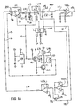
- An oscillator, U6 typically a low-power CMOS version of a 555 timer such as a 7555, is used to generate a control signal for the LED current.
- Transistors Ql and Q2 amplify the output of the oscillator U6.
- a transformer Tl serves to match the drive requirement of 1.5 volts for the LED 10 to the circuit's higher drive voltage of typically 6 to 10 volts.
- the transformer Tl is typically a pulse transformer with a 4:1 turns ratio.
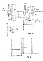
- a current regulator U9 and a capacitor C5 serve to isolate the high pulses of current from creating voltage pulses on the power supply for the rest of the transmitter circuit by limiting the peak current to around 1 mA and storing charge in the capacitor between the pulses supplied to the LED 10. Then, the current supplied to the LED 10 comes primarily from the charge stored in the capacitor C5.
- Figure 2 shows the waveform of the current supplied to the LED 10.
- Light pulses are transmitted from the LED 10 to a light detector 20 by a fibre optic cable shown schematically at 15. Varying attenuation is effected, typically by application of bending to the fibre 15 or changing of coupling at a discontinuity in the fibre.
- the light detector 20 converts the received light into an electrical signal, typically a current. In the form of implementation shown in Figure lA, the detector 20 supplies a current (in pulse form) to the following circuitry.
- a preamplifier (preamp) Ul converts the current pulses from the detector 20 into voltage pulses.
- the integrated circuit used for the preamplifier Ul must be capable of low power operation and have sufficient bandwidth to amplify the pulses faithfully.
- a type T1C251 integrated circuit available from Texas Instruments is a programmable CMOS operational amplifier (opamp) which meets these requirements. In a low-current mode thereof it meets the power requirements.
- a high-current mode thereof has the bandwidth necessary for amplifying the pulses.
- the amplifier Ul is switched into the high power and high bandwidth mode only when a pulse is present, being controlled by the drive signal to the LED 10 via a line 12. Thus, it is not drawing the high power during periods when such is not necessary to the circuit's operation.
- a peak-following sample and hold function is performed by the combination of a capacitor C1, a diode CR1 and a switch Sl (which is part of a switch circuit assembly U5 which may be a type 4066 circuit).
- the switch Sl discharges the voltage on the capacitor Cl at the beginning of the light pulse.
- the switch S1 is controlled by a one-shot multivibrator circuit in an integrated circuit U4 (MC14538 or MC14528) which is triggered by the beginning of the pulse to the LED 10 over the line 12. Then, the capacitor Cl is charged through the diode CR1 from the output of the preamplifier Ul.
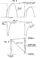
- the capacitor Cl stops charging at the peak of the output of the preamplifier and the diode CR1 prevents the immediate discharge necessary to follow the downside of the pulse.
- Figure 3 shows this operation.
- An operational amplifier U3 buffers the voltage on the capacitor Cl, allowing the following circuitry to operate without affecting the signal on the capacitor Cl.
- a second sample and hold operation is performed by a switch S2 (also part of the switch circuit assembly U5), a resistor R37, and a capacitor C2.
- the switch S2 is closed after the LED pulse has finished.
- the peak of the pulse as stored in the capacitor Cl is sampled and stored in the capacitor C2.
- the resistor R37 and capacitor C2 perform a low-pass filtering action to reduce the sampling frequency (LED pulse frequency) component from the signal received from the optical system.
- Figure 4 shows the output of this circuit, which is on a line 14.
- Operational amplifiers U2b and U2c form a feedback control loop, which loop compares the peaks of the pulses with signal ground and returns a current to the input of the preamplifier Ul over a line 16 to drive the peaks back to ground. This is necessary since the pulses are quite large, being sufficient to drive the preamplifier Ul into saturation.
- Figure 5 shows the signal and the typically 2 percent maximum modulation. The effect of this circuit on the signal is shown also.
- the operational amplifier U2b is an integrator (or low pass filter) so that the adjustment effect is slow-acting. Thus, long term variations are removed and signal components are not affected.
- a switch S3 controls the operation of this loop so that it only operates immediately following the end of the pulse to the LED 10 by a line 18. This removes any influences from decay on the voltage of the capacitor Cl between signal pulses.
- An internal power supply is regulated by a circuit U8a and associated components, including a transistor Q3, which is a series pass field effect transistor (FET).
- An operational amplifier U2d divides the internal power supply, typically ID volts, into two 5-volt supplies with signal ground in the middle. This allows for operation of amplifiers that have voltage swing and below signal ground.
- the typically low level sine wave signal on the line 14 from the second sample and hold arrangement is operated on by a hysteresis comparator U8c, which converts it to a rectangular or square wave.
- This rectangular or square wave is used to trigger a one-shot multivibrator U7 to give a fixed length, fixed amplitude pulse for each cycle of the sine wave signal from the optical system.
- This is then averaged by a resistor R19 and a capacitor C9 and used to control a 4-40 mA output signal by a circuit comprising an operational amplifier UBb, a transistor Q4 and associated resistors.
- the multivibrator U7 may be an MC14538, and is connected to the hysteresis comparator U8c by a line 19.
Landscapes
- Physics & Mathematics (AREA)
- General Physics & Mathematics (AREA)
- Fluid Mechanics (AREA)
- Electromagnetism (AREA)
- Amplifiers (AREA)
- Optical Transform (AREA)
- Arrangements For Transmission Of Measured Signals (AREA)
- Photometry And Measurement Of Optical Pulse Characteristics (AREA)
- Measurement Of Current Or Voltage (AREA)
Applications Claiming Priority (2)
| Application Number | Priority Date | Filing Date | Title |
|---|---|---|---|
| US612284 | 1984-05-21 | ||
| US06/612,284 US4628197A (en) | 1984-05-21 | 1984-05-21 | Electronics for fiber optic vortex shedding flow meter |
Publications (2)
| Publication Number | Publication Date |
|---|---|
| EP0165697A1 true EP0165697A1 (fr) | 1985-12-27 |
| EP0165697B1 EP0165697B1 (fr) | 1988-11-23 |
Family
ID=24452516
Family Applications (1)
| Application Number | Title | Priority Date | Filing Date |
|---|---|---|---|
| EP19850303292 Expired EP0165697B1 (fr) | 1984-05-21 | 1985-05-09 | Dispositif de capteur optique |
Country Status (13)
| Country | Link |
|---|---|
| US (1) | US4628197A (fr) |
| EP (1) | EP0165697B1 (fr) |
| JP (1) | JPS60256014A (fr) |
| KR (1) | KR900004882B1 (fr) |
| AU (1) | AU572294B2 (fr) |
| BR (1) | BR8501765A (fr) |
| CA (1) | CA1227356A (fr) |
| DE (1) | DE3566452D1 (fr) |
| ES (1) | ES8609702A1 (fr) |
| HK (1) | HK77189A (fr) |
| IN (1) | IN162597B (fr) |
| MX (1) | MX162204A (fr) |
| SG (1) | SG46889G (fr) |
Cited By (6)
| Publication number | Priority date | Publication date | Assignee | Title |
|---|---|---|---|---|
| EP0234680A1 (fr) * | 1986-01-21 | 1987-09-02 | The Babcock & Wilcox Company | Traitement de signaux de capteurs provenant de détecteurs de lumière |
| EP0232007A3 (fr) * | 1986-02-03 | 1989-08-09 | International Control Automation Finance S.A. | Traitement de signaux générés optiquement |
| GB2238380A (en) * | 1989-11-23 | 1991-05-29 | Hughes Microelectronics Ltd | Vortex shedding flowmeter |
| DE4421075A1 (de) * | 1994-04-07 | 1995-10-12 | Landis & Gyr Business Support | Schaltungsanordnung zur Übertragung von Impulsen |
| DE19638912A1 (de) * | 1996-09-23 | 1998-03-26 | Teves Gmbh Alfred | Drehwinkelsensor mit CCD-Zeile und periodisch angesteuerter Lichtquelle |
| US6483104B1 (en) | 1996-09-23 | 2002-11-19 | Valeo Schalter Und Sensoren Gmbh | Rotational angle sensor using a CCD line with enhanced measuring precision |
Families Citing this family (4)
| Publication number | Priority date | Publication date | Assignee | Title |
|---|---|---|---|---|
| GB8713699D0 (en) * | 1987-06-11 | 1987-07-15 | British Telecomm | Optical receiver circuit |
| US4958070A (en) * | 1988-11-07 | 1990-09-18 | The Babcock & Wilcox Company | Digital electronics for controlling a fiber optic shedding flowmeter |
| JP2018084462A (ja) * | 2016-11-22 | 2018-05-31 | 株式会社ミツトヨ | エンコーダ及び信号処理回路 |
| CN109294901A (zh) * | 2018-11-01 | 2019-02-01 | 福建省博凯科技有限公司 | 一段式热对流pcr仪及控制方法 |
Citations (2)
| Publication number | Priority date | Publication date | Assignee | Title |
|---|---|---|---|---|
| GB2093997A (en) * | 1981-03-03 | 1982-09-08 | Marconi Co Ltd | Flowmeter |
| DE3217078A1 (de) * | 1981-05-18 | 1982-12-02 | ASEA AB, 72183 Västerås | Faseroptische messanordnung |
Family Cites Families (6)
| Publication number | Priority date | Publication date | Assignee | Title |
|---|---|---|---|---|
| US4011754A (en) * | 1976-06-07 | 1977-03-15 | International Standard Electric Corporation | Flowmeter |
| JPS5698613A (en) * | 1980-01-11 | 1981-08-08 | Nissan Motor Co Ltd | Fuel control device |
| JPS6027367B2 (ja) * | 1980-10-28 | 1985-06-28 | 横河電機株式会社 | 光ファイバ流量計 |
| JPS603423U (ja) * | 1983-06-20 | 1985-01-11 | トキコ株式会社 | 流速・流量検出装置 |
| US4552026A (en) * | 1984-10-22 | 1985-11-12 | The Babcock & Wilcox Company | Sensor for a vortex shedding flowmeter |
| DE3534273A1 (de) * | 1985-09-26 | 1987-04-02 | Basf Ag | Verfahren zur herstellung von vinylamin-einheiten enthaltenden wasserloeslichen copolymerisaten und deren verwendung als nass- und trockenverfestigungsmittel fuer papier |
-
1984
- 1984-05-21 US US06/612,284 patent/US4628197A/en not_active Expired - Fee Related
-
1985
- 1985-02-22 CA CA000474958A patent/CA1227356A/fr not_active Expired
- 1985-03-05 KR KR1019850001364A patent/KR900004882B1/ko not_active Expired
- 1985-03-12 ES ES541172A patent/ES8609702A1/es not_active Expired
- 1985-03-15 IN IN196/CAL/85A patent/IN162597B/en unknown
- 1985-04-10 BR BR8501765A patent/BR8501765A/pt not_active IP Right Cessation
- 1985-05-09 EP EP19850303292 patent/EP0165697B1/fr not_active Expired
- 1985-05-09 MX MX205256A patent/MX162204A/es unknown
- 1985-05-09 DE DE8585303292T patent/DE3566452D1/de not_active Expired
- 1985-05-16 AU AU42570/85A patent/AU572294B2/en not_active Ceased
- 1985-05-20 JP JP60106227A patent/JPS60256014A/ja active Granted
-
1989
- 1989-07-31 SG SG46889A patent/SG46889G/en unknown
- 1989-09-28 HK HK771/89A patent/HK77189A/en not_active IP Right Cessation
Patent Citations (2)
| Publication number | Priority date | Publication date | Assignee | Title |
|---|---|---|---|---|
| GB2093997A (en) * | 1981-03-03 | 1982-09-08 | Marconi Co Ltd | Flowmeter |
| DE3217078A1 (de) * | 1981-05-18 | 1982-12-02 | ASEA AB, 72183 Västerås | Faseroptische messanordnung |
Cited By (6)
| Publication number | Priority date | Publication date | Assignee | Title |
|---|---|---|---|---|
| EP0234680A1 (fr) * | 1986-01-21 | 1987-09-02 | The Babcock & Wilcox Company | Traitement de signaux de capteurs provenant de détecteurs de lumière |
| EP0232007A3 (fr) * | 1986-02-03 | 1989-08-09 | International Control Automation Finance S.A. | Traitement de signaux générés optiquement |
| GB2238380A (en) * | 1989-11-23 | 1991-05-29 | Hughes Microelectronics Ltd | Vortex shedding flowmeter |
| DE4421075A1 (de) * | 1994-04-07 | 1995-10-12 | Landis & Gyr Business Support | Schaltungsanordnung zur Übertragung von Impulsen |
| DE19638912A1 (de) * | 1996-09-23 | 1998-03-26 | Teves Gmbh Alfred | Drehwinkelsensor mit CCD-Zeile und periodisch angesteuerter Lichtquelle |
| US6483104B1 (en) | 1996-09-23 | 2002-11-19 | Valeo Schalter Und Sensoren Gmbh | Rotational angle sensor using a CCD line with enhanced measuring precision |
Also Published As
| Publication number | Publication date |
|---|---|
| SG46889G (en) | 1989-12-22 |
| HK77189A (en) | 1989-10-06 |
| CA1227356A (fr) | 1987-09-29 |
| AU4257085A (en) | 1986-11-27 |
| JPS60256014A (ja) | 1985-12-17 |
| BR8501765A (pt) | 1986-06-17 |
| KR900004882B1 (ko) | 1990-07-09 |
| ES8609702A1 (es) | 1986-09-01 |
| MX162204A (es) | 1991-04-08 |
| IN162597B (fr) | 1988-06-18 |
| JPH0512760B2 (fr) | 1993-02-18 |
| EP0165697B1 (fr) | 1988-11-23 |
| DE3566452D1 (en) | 1988-12-29 |
| KR850008412A (ko) | 1985-12-16 |
| ES541172A0 (es) | 1986-09-01 |
| US4628197A (en) | 1986-12-09 |
| AU572294B2 (en) | 1988-05-05 |
Similar Documents
| Publication | Publication Date | Title |
|---|---|---|
| US4656353A (en) | Variable pulse rate led electronics for a fiber optic vortex shedding flowmeter | |
| EP0290243A2 (fr) | Système de transducteurs à alimentation optique | |
| US6961665B2 (en) | Power management mechanism for loop powered time of flight and level measurement systems | |
| EP0165697B1 (fr) | Dispositif de capteur optique | |
| HU181275B (en) | Apparatus for automatic controlling output power of the transmitter in a fibre-optics system | |
| JPS6398099A (ja) | センサ装置からの信号の伝送方法 | |
| EP0232007A2 (fr) | Traitement de signaux générés optiquement | |
| JPH026758A (ja) | 電圧・周波数変換器および光導波管伝送方式におけるその用途 | |
| GB2165116B (en) | Optical receiver | |
| CA2237779A1 (fr) | Circuit de controle pour compteurs | |
| US5012097A (en) | Radiation measuring apparatus | |
| DE3271796D1 (en) | Arrangement for measuring physical parameters with an optical sensor | |
| HUT43703A (en) | Flame guard sensing variable radiation with suppression of disturbing signal | |
| Bonen et al. | A novel optoelectronic interface-circuit design for sensing applications | |
| KR890016399A (ko) | 광학적으로 결합된 원격센서장치 및 시스템 | |
| CN1021127C (zh) | 控制光纤涡散式流量计的电子数字电路 | |
| CN1109977A (zh) | 人体检测器 | |
| JPS5730921A (en) | Pressure sensor | |
| RU1792680C (ru) | Индикатор дл слепых | |
| FR2409625A1 (fr) | Installation permettant de prelever une tension sur un condensateur tampon d'un onduleur | |
| JPS60230038A (ja) | 光電式アナログ煙感知器の受光回路 | |
| JPS60155980A (ja) | 波形観測用プロ−ブ | |
| GB2291511A (en) | A method of stabilising the output intensity and or output frequency of an optical light source using an electronic counting technique | |
| JPS6416037A (en) | Optical receiver | |
| SE8107186L (en) | Physical or electrical valve measuring unit - uses optical sensor supplying pulses, suitable for multiplexing, to oscillator circuit resonating according to detected light level |
Legal Events
| Date | Code | Title | Description |
|---|---|---|---|
| PUAI | Public reference made under article 153(3) epc to a published international application that has entered the european phase |
Free format text: ORIGINAL CODE: 0009012 |
|
| AK | Designated contracting states |
Designated state(s): DE FR GB IT SE |
|
| 17P | Request for examination filed |
Effective date: 19860509 |
|
| 17Q | First examination report despatched |
Effective date: 19871009 |
|
| ITF | It: translation for a ep patent filed | ||
| GRAA | (expected) grant |
Free format text: ORIGINAL CODE: 0009210 |
|
| AK | Designated contracting states |
Kind code of ref document: B1 Designated state(s): DE FR GB IT SE |
|
| REF | Corresponds to: |
Ref document number: 3566452 Country of ref document: DE Date of ref document: 19881229 |
|
| ET | Fr: translation filed | ||
| PLBE | No opposition filed within time limit |
Free format text: ORIGINAL CODE: 0009261 |
|
| STAA | Information on the status of an ep patent application or granted ep patent |
Free format text: STATUS: NO OPPOSITION FILED WITHIN TIME LIMIT |
|
| 26N | No opposition filed | ||
| REG | Reference to a national code |
Ref country code: GB Ref legal event code: 732 |
|
| ITTA | It: last paid annual fee | ||
| EAL | Se: european patent in force in sweden |
Ref document number: 85303292.8 |
|
| PGFP | Annual fee paid to national office [announced via postgrant information from national office to epo] |
Ref country code: FR Payment date: 19960415 Year of fee payment: 12 |
|
| PGFP | Annual fee paid to national office [announced via postgrant information from national office to epo] |
Ref country code: SE Payment date: 19960417 Year of fee payment: 12 |
|
| PGFP | Annual fee paid to national office [announced via postgrant information from national office to epo] |
Ref country code: DE Payment date: 19960423 Year of fee payment: 12 |
|
| PGFP | Annual fee paid to national office [announced via postgrant information from national office to epo] |
Ref country code: GB Payment date: 19960425 Year of fee payment: 12 |
|
| PG25 | Lapsed in a contracting state [announced via postgrant information from national office to epo] |
Ref country code: GB Effective date: 19970509 |
|
| PG25 | Lapsed in a contracting state [announced via postgrant information from national office to epo] |
Ref country code: SE Effective date: 19970510 |
|
| GBPC | Gb: european patent ceased through non-payment of renewal fee |
Effective date: 19970509 |
|
| PG25 | Lapsed in a contracting state [announced via postgrant information from national office to epo] |
Ref country code: FR Free format text: LAPSE BECAUSE OF NON-PAYMENT OF DUE FEES Effective date: 19980130 |
|
| EUG | Se: european patent has lapsed |
Ref document number: 85303292.8 |
|
| PG25 | Lapsed in a contracting state [announced via postgrant information from national office to epo] |
Ref country code: DE Free format text: LAPSE BECAUSE OF NON-PAYMENT OF DUE FEES Effective date: 19980203 |
|
| REG | Reference to a national code |
Ref country code: FR Ref legal event code: ST |