EP0165698A1 - Rückkopplungsfehlerdetektor für Servomotor - Google Patents
Rückkopplungsfehlerdetektor für Servomotor Download PDFInfo
- Publication number
- EP0165698A1 EP0165698A1 EP85303315A EP85303315A EP0165698A1 EP 0165698 A1 EP0165698 A1 EP 0165698A1 EP 85303315 A EP85303315 A EP 85303315A EP 85303315 A EP85303315 A EP 85303315A EP 0165698 A1 EP0165698 A1 EP 0165698A1
- Authority
- EP
- European Patent Office
- Prior art keywords
- signal
- providing
- responsive
- absolute value
- accordance
- Prior art date
- Legal status (The legal status is an assumption and is not a legal conclusion. Google has not performed a legal analysis and makes no representation as to the accuracy of the status listed.)
- Granted
Links
Images
Classifications
-
- G—PHYSICS
- G05—CONTROLLING; REGULATING
- G05D—SYSTEMS FOR CONTROLLING OR REGULATING NON-ELECTRIC VARIABLES
- G05D1/00—Control of position, course, altitude or attitude of land, water, air or space vehicles, e.g. using automatic pilots
- G05D1/0055—Control of position, course, altitude or attitude of land, water, air or space vehicles, e.g. using automatic pilots with safety arrangements
- G05D1/0077—Control of position, course, altitude or attitude of land, water, air or space vehicles, e.g. using automatic pilots with safety arrangements using redundant signals or controls
-
- G—PHYSICS
- G05—CONTROLLING; REGULATING
- G05B—CONTROL OR REGULATING SYSTEMS IN GENERAL; FUNCTIONAL ELEMENTS OF SUCH SYSTEMS; MONITORING OR TESTING ARRANGEMENTS FOR SUCH SYSTEMS OR ELEMENTS
- G05B23/00—Testing or monitoring of control systems or parts thereof
- G05B23/02—Electric testing or monitoring
- G05B23/0205—Electric testing or monitoring by means of a monitoring system capable of detecting and responding to faults
- G05B23/0218—Electric testing or monitoring by means of a monitoring system capable of detecting and responding to faults characterised by the fault detection method dealing with either existing or incipient faults
- G05B23/0224—Process history based detection method, e.g. whereby history implies the availability of large amounts of data
- G05B23/0227—Qualitative history assessment, whereby the type of data acted upon, e.g. waveforms, images or patterns, is not relevant, e.g. rule based assessment; if-then decisions
- G05B23/0235—Qualitative history assessment, whereby the type of data acted upon, e.g. waveforms, images or patterns, is not relevant, e.g. rule based assessment; if-then decisions based on a comparison with predetermined threshold or range, e.g. "classical methods", carried out during normal operation; threshold adaptation or choice; when or how to compare with the threshold
-
- G—PHYSICS
- G05—CONTROLLING; REGULATING
- G05B—CONTROL OR REGULATING SYSTEMS IN GENERAL; FUNCTIONAL ELEMENTS OF SUCH SYSTEMS; MONITORING OR TESTING ARRANGEMENTS FOR SUCH SYSTEMS OR ELEMENTS
- G05B9/00—Safety arrangements
- G05B9/02—Safety arrangements electric
Definitions
- This invention relates to electric servomotors, particularly with respect to monitors therefor.
- Servomotors are prevalent in various technologies for positioning output members in accordance with input command signals.
- Servomotors for example, are utilised in automatic flight control systems for aircraft for positioning the aerodynamic control surfaces such as the ailerons, elevators and rudders as well as for positioning the engine throttles.
- feedback paths are utilised around such servomotors for providing, for example, motor damping.
- a tachometer generator coupled to the motor output shaft provides a feedback signal proportional to the rate of rotation of the motor. Since safety and reliability are of paramount importance in the design of automatic flight control systems, dangerous failures such as servomotor hardover or oscillatory conditions resulting from servo feedback faults must be obviated.
- a servo motor feedback fault detector that combines the metor drive voltage with the current flowing through the motor as a result of applying the drive voltage thereto, and with a tachometer signal proportional to the rate of rotation of the motor to provide a combined signal.
- a threshold signal is generated in accordance with the current flowing through the motor and the tachometer signal utilising tolerance factors applied to these parameters. When the voltage, current and rate combination signal exceeds the threshold, a fault is indicated.
- servomotor and servo feedback faults are detected by monitoring the correlation between the measured motor parameters of motor drive voltage, motor current and motor rate.
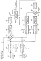
- a servomotor feedback fault detector in accordance with the present invention will now be described in greater detail, by way of example, with reference to the accompanying sole figure of drawings which is a schematic block diagram of the detector.
- the (IM) (R M ) term of the equation represents the motor heat loss due to the motor resistance and the resistance of the associated interconnecting wires.
- the (K) (V T ) term represents the back EMF developed across the motor armature due to the motor rotation. This back E MF parameter is manifested by the voltage from a tachometer geared to the output shaft of the servomotor or included internally therewith. The ratio (K) depends upon the configurations of the tachometer, of the motor and on the gearing therebetween. The tachometer output voltage is utilised to provide damping feedback around the servomotor in a conventional manner.
- the inductive term is the voltage developed across the motor inductance due to variations in motor current flow.
- Equation 1 may be reduced to a steady state approximation by deleting the inductive term. This is permitted for monitoring since the L/R time constant in servomotors utilised in automatic flight control systems is typically small compared to the servo motion time constant represented by the tachometer term.
- the motor drive voltage V is applied on a lead 10
- the motor current I m is applied on a lead 11
- the motor rate tachometer signal V T is applied on a lead 12
- the motor resistance value R M is applied on a lead 13
- the tachometer voltage to armature back EMF ratio K is applied on a lead 14.
- the motor current I M on the lead 11 is multiplied at 15 by the resistance value R M on the lead 13 to form a product signal on a lead 16.
- the multiplier 15 forms the I R term of expression 2 above.
- the motor rate signal V T on the lead 12 is multipled at by the ratio K on the lead 14 to provide a product signal on a lead 18.
- the multiplier 17 forms the rate feedback term of expression 2 above.
- the motor drive voltage V M on the lead 10 and the product signals on the leads 16 and 18 are algebraically summed at 19 to form a summation signal on a lead 20.
- the absolute value of the summation signal on the lead 20 is taken at block 21 and the absolute value signal from this block filtered at 22 to provide a monitor error signal on a lead 23.
- the filter 22 is a low-pass filter implemented conventionally as a lag filter to smooth the signal from the block 21 and filter noise therefrom. In a sampled data implementation of the present invention, the filter 22 averages the signal from the block 21 over several samples.
- the absolute value taken at block 21 is provided effectively to rectify oscillatory error signals so as to provide a non-zero value therefor. If the absolute value were not taken, oscillatory error signals would average to zero through the filter 22, thereby not detecting the failure that caused the oscillatory error signal.
- the components 10-23 of the drawing implements the left-hand side of expression 2 above.
- the motor resistance tolerance K and the motor tachometer tolerance K discussed above are applied on leads 24 and 25, respectively.
- the product signal on the lead 16 is mulitiplied at 26 by the motor reistance tolerance on the lead 24 to provide a product signal on a lead 27.
- the product signal on the lead 18 is multiplied at 28 by the motor tachometer tolerance signal on the lead 25 to form a product signal on a lead 29.
- the resistance tolerance K R is the total tolerance permitted in the motor resistance value to accommodate such factors as the resistance of the motor varying over temperature.
- the tachometer tolerance K is the total permitted tolerance with respect to the ratio K resulting from such factors as variations in the ratio K due to geometrical anomalies of the motor and tachometer such as out-of-roundness of rotating elements and asymmetry in winding structures. Generally, the measured parameters themselves have tolerances associated therewith which are reflected in the tolerances K R and K T .
- the product signals on the leads 27 and 29 are applied to absolute value taking blocks 30 and 31, respectively, which provide the respective absolute values of the product signals on the leads 27 and 29.
- the algebraic sum of the signals from the absolute value blocks 30 and 31 is derived at 32.
- the algebraic sum provided at 32 includes a measurement offset factor V applied on a lead 33.
- the offset factor V D compensates for offsets in the measurements provided in the system in which the invention is implemented. For example, in a digital sampled data embodiment of the invention, the factor V D compensates for offsets in the measurements associated with analogue-to-digital and digital-to- analogue converters, buffers, multiplexers, operational amplifiers and the like.
- the summation signal from the summing element 32 is passed through a low-pass filter 34 to provide a threshold signal on a lead 35.
- the absolute value blocks 30 and 31 and the filter 34 are implemented in a manner similar to and utilised for the reasons discussed above with respect to the absolute value block 21 and the filter 22.
- the components 24-35 embody expression 3 above.
- the inputs to the multipliers 26 and 28 may alternatively be connected to the leads 11 and 12, respectively, rather than connected as illustrated.
- the tolerance factors K and K T will be adjusted to account for the resistance value RM and the tachometer ratio K, respectively.
- the error signal on the lead 23 and the threshold signal on the lead 35 are applied to a decision block 36 which compares the error signal with the threshold signal and provides a fault-detected signal on a lead 37 when the error signal exceeds the threshold.
- the fault-detected signal on the lead 37 may be utilised to set an appropriate failure flag or may be utilised to disable an autopilot servo or channel as required.
- the servomotor feedback fault detector of the present invention detects faults in the servo feedback that may precipitate such dangerous situations as autopilot hardovers and oscillatory conditions.
- the fault detector of the present invention also detects open circuit conditions with respect to the servomotor as well as latent faults in the monitored and measured data.
- the tolerance signal provided on the lead 35 dynamically adjusts the threshold for the decision circuit 36 in accordance with the dynamic conditions experienced by the servomotor.
- the tolerance is provided primarily in accordance with the tachometer signal. Since traditionally the tolerance on the tachometer signal is approximately 10%, it is desired to tighten up the threshold on the lead 35 under such conditions so that the monitor will rapidly detect failures. Accordingly, an appropriate value for the tolerance factor K T is 12.5%.
- the tolerance of expression 3 is due primarily to the motor current.
- the monitor of the present invention is approximately three times more sensitive to failure indication when the servomotor is free-running than when the servomotor is stalled when utilising these values for K R and K T .
- the present invention as described above and illustrated in the sole drawing may be implemented in hardware utilising conventional analogue circuits or conventional discrete digital circuits.
- the present invention may advantageously also be utilised in a digital sampled data system such as an automatic flight control system implemented with a digital computer.
- the motor drive voltage, motor current and motor rate signals may be applied to the input of the computer through appropriate conversion circuitry for processing within the computer in accordance with the functions described above to provide the fault detected signal.
- the computer may also be utilised to close the feedback loop around the servomotor.
- the tachometer signal applied to the computer input may be utilised by the computer in conjunction with external data for generating the positioning command to the servomotor.
Landscapes
- Engineering & Computer Science (AREA)
- Physics & Mathematics (AREA)
- General Physics & Mathematics (AREA)
- Automation & Control Theory (AREA)
- Aviation & Aerospace Engineering (AREA)
- Radar, Positioning & Navigation (AREA)
- Remote Sensing (AREA)
- Control Of Electric Motors In General (AREA)
- Testing And Monitoring For Control Systems (AREA)
Applications Claiming Priority (2)
| Application Number | Priority Date | Filing Date | Title |
|---|---|---|---|
| US06/611,305 US4536689A (en) | 1984-05-17 | 1984-05-17 | Servomotor feedback fault detector |
| US611305 | 1984-05-17 |
Publications (2)
| Publication Number | Publication Date |
|---|---|
| EP0165698A1 true EP0165698A1 (de) | 1985-12-27 |
| EP0165698B1 EP0165698B1 (de) | 1988-11-02 |
Family
ID=24448501
Family Applications (1)
| Application Number | Title | Priority Date | Filing Date |
|---|---|---|---|
| EP85303315A Expired EP0165698B1 (de) | 1984-05-17 | 1985-05-10 | Rückkopplungsfehlerdetektor für Servomotor |
Country Status (5)
| Country | Link |
|---|---|
| US (1) | US4536689A (de) |
| EP (1) | EP0165698B1 (de) |
| JP (1) | JPH0667246B2 (de) |
| CA (1) | CA1208695A (de) |
| DE (1) | DE3566067D1 (de) |
Cited By (1)
| Publication number | Priority date | Publication date | Assignee | Title |
|---|---|---|---|---|
| CN106301610A (zh) * | 2016-08-29 | 2017-01-04 | 北京航空航天大学 | 一种超外差接收机的自适应故障检测和诊断方法及装置 |
Families Citing this family (7)
| Publication number | Priority date | Publication date | Assignee | Title |
|---|---|---|---|---|
| JPH0646786B2 (ja) * | 1985-04-19 | 1994-06-15 | ソニー株式会社 | マルチ走査形テレビジヨン受像機の水平偏向回路 |
| JP2789633B2 (ja) * | 1989-01-17 | 1998-08-20 | トヨタ自動車株式会社 | サーボモータの負荷監視装置 |
| JP3652084B2 (ja) * | 1997-10-08 | 2005-05-25 | 多摩川精機株式会社 | サーボモータ駆動方法 |
| US6225590B1 (en) * | 1998-05-26 | 2001-05-01 | Medar, Inc. | Method for determining a condition of a resistance spotwelding system or a workpiece in the system |
| US7159479B1 (en) * | 2003-09-25 | 2007-01-09 | Lockheed Martin Corporation | Active damper for stabilized mirrors |
| US7239968B2 (en) * | 2004-01-28 | 2007-07-03 | Valere Power, Inc. | Method and apparatus for predicting fan failure |
| US20080296521A1 (en) * | 2007-05-30 | 2008-12-04 | General Electric Company | Method and system for reducing or eliminating uncontrolled motion in a motion control system |
Citations (3)
| Publication number | Priority date | Publication date | Assignee | Title |
|---|---|---|---|---|
| DE2021507A1 (de) * | 1969-05-05 | 1970-11-12 | Gen Electric | Fehlerwaechterschaltung fuer die Rueckkopplung eines Regelsystems |
| AT302456B (de) * | 1968-05-17 | 1972-10-10 | Elin Union Ag | Einrichtung zum Schutz gegen Stillstands-Überlastung drehzahlgeregelter Gleichstrommomotoren oder anderer Kollektormaschinen |
| US4275342A (en) * | 1979-11-16 | 1981-06-23 | Fujitsu Fanuc Limited | Abnormality detecting system for DC motor control apparatus |
Family Cites Families (7)
| Publication number | Priority date | Publication date | Assignee | Title |
|---|---|---|---|---|
| US3199013A (en) * | 1963-05-31 | 1965-08-03 | United Aircraft Corp | Rate responsive compensation change circuit |
| US3935523A (en) * | 1972-12-05 | 1976-01-27 | Adaptronics, Inc. | Non-minimum phase linear controller for hydraulic mechanisms |
| US4092716A (en) * | 1975-07-11 | 1978-05-30 | Mcdonnell Douglas Corporation | Control means and method for controlling an object |
| US4094481A (en) * | 1977-06-30 | 1978-06-13 | Sperry Rand Corporation | Fail passive dual servo with continuous motor speed and acceleration and monitoring |
| US4171115A (en) * | 1977-12-12 | 1979-10-16 | Sperry Rand Corporation | Stability augmentation system for relaxed static stability aircraft |
| US4209734A (en) * | 1978-03-27 | 1980-06-24 | Sperry Corporation | Dynamic equalization system for dual channel automatic pilot |
| JPS58215978A (ja) * | 1982-06-08 | 1983-12-15 | Fanuc Ltd | ロボツト駆動装置におけるサ−ボ異常検出回路 |
-
1984
- 1984-05-17 US US06/611,305 patent/US4536689A/en not_active Expired - Lifetime
-
1985
- 1985-01-14 CA CA000472002A patent/CA1208695A/en not_active Expired
- 1985-04-05 JP JP60072500A patent/JPH0667246B2/ja not_active Expired - Lifetime
- 1985-05-10 DE DE8585303315T patent/DE3566067D1/de not_active Expired
- 1985-05-10 EP EP85303315A patent/EP0165698B1/de not_active Expired
Patent Citations (3)
| Publication number | Priority date | Publication date | Assignee | Title |
|---|---|---|---|---|
| AT302456B (de) * | 1968-05-17 | 1972-10-10 | Elin Union Ag | Einrichtung zum Schutz gegen Stillstands-Überlastung drehzahlgeregelter Gleichstrommomotoren oder anderer Kollektormaschinen |
| DE2021507A1 (de) * | 1969-05-05 | 1970-11-12 | Gen Electric | Fehlerwaechterschaltung fuer die Rueckkopplung eines Regelsystems |
| US4275342A (en) * | 1979-11-16 | 1981-06-23 | Fujitsu Fanuc Limited | Abnormality detecting system for DC motor control apparatus |
Cited By (1)
| Publication number | Priority date | Publication date | Assignee | Title |
|---|---|---|---|---|
| CN106301610A (zh) * | 2016-08-29 | 2017-01-04 | 北京航空航天大学 | 一种超外差接收机的自适应故障检测和诊断方法及装置 |
Also Published As
| Publication number | Publication date |
|---|---|
| EP0165698B1 (de) | 1988-11-02 |
| DE3566067D1 (en) | 1988-12-08 |
| JPS60245488A (ja) | 1985-12-05 |
| US4536689A (en) | 1985-08-20 |
| CA1208695A (en) | 1986-07-29 |
| JPH0667246B2 (ja) | 1994-08-24 |
Similar Documents
| Publication | Publication Date | Title |
|---|---|---|
| US4355358A (en) | Adaptive aircraft actuator fault detection | |
| US4035705A (en) | Fail-safe dual channel automatic pilot with maneuver limiting | |
| US4162438A (en) | Dual servo automatic pilot with improved failure monitoring | |
| EP0165698B1 (de) | Rückkopplungsfehlerdetektor für Servomotor | |
| US4078750A (en) | Speed-variable limits in fail-safe actuators | |
| US4488198A (en) | Protective circuit for clutchless parallel generating system | |
| US4447788A (en) | Method for optimizing the power input of a plurality of hysteresis motors connected in parallel | |
| CA2197468C (en) | Integrator management for redundant active hand controllers | |
| EP4476441B1 (de) | Verfahren zur steuerung des betriebs einer windenergieanlage und windenergieanlage | |
| US4366427A (en) | Protective method and apparatus for a controlled current inverter and motor control system | |
| US4334266A (en) | Numerical control system with following error monitor | |
| EP0657991B1 (de) | Signalerfassungsschaltung für digitale Regelung | |
| GB1600444A (en) | Control systems for aircraft | |
| US3283229A (en) | Dual redundant, adaptive motor control with fail safe features | |
| US12362691B2 (en) | Speed control of mechanically paralleled electrical drives without intercommunication buses | |
| US4594714A (en) | Dual-actuator monitor | |
| US4451770A (en) | Method and apparatus for determining the resistance of an AC motor stator | |
| US4171505A (en) | Fault detecting system for a control system | |
| GB2047022A (en) | Method and apparatus for a variable frequency inverter system having commutation fault detection and correction capabilities | |
| US4518905A (en) | Current control of synchro power amplifiers | |
| EP0130547B1 (de) | Spannungsschutzeinrichtung für eine Kraftanlage mit variabler Frequenz | |
| CA1140989A (en) | Protective circuit for clutchless parallel generating system | |
| JPS5834483Y2 (ja) | 速度制御装置の故障検出装置 | |
| RU2008642C1 (ru) | Стенд для испытаний топливно-регулирующей аппаратуры газотурбинных двигателей | |
| JPS6146191A (ja) | 電動機制御装置 |
Legal Events
| Date | Code | Title | Description |
|---|---|---|---|
| PUAI | Public reference made under article 153(3) epc to a published international application that has entered the european phase |
Free format text: ORIGINAL CODE: 0009012 |
|
| AK | Designated contracting states |
Designated state(s): DE FR GB IT NL |
|
| 17P | Request for examination filed |
Effective date: 19860220 |
|
| 17Q | First examination report despatched |
Effective date: 19870320 |
|
| RAP1 | Party data changed (applicant data changed or rights of an application transferred) |
Owner name: HONEYWELL INC. |
|
| ITF | It: translation for a ep patent filed | ||
| GRAA | (expected) grant |
Free format text: ORIGINAL CODE: 0009210 |
|
| AK | Designated contracting states |
Kind code of ref document: B1 Designated state(s): DE FR GB IT NL |
|
| REF | Corresponds to: |
Ref document number: 3566067 Country of ref document: DE Date of ref document: 19881208 |
|
| ET | Fr: translation filed | ||
| PLBE | No opposition filed within time limit |
Free format text: ORIGINAL CODE: 0009261 |
|
| STAA | Information on the status of an ep patent application or granted ep patent |
Free format text: STATUS: NO OPPOSITION FILED WITHIN TIME LIMIT |
|
| 26N | No opposition filed | ||
| ITTA | It: last paid annual fee | ||
| PGFP | Annual fee paid to national office [announced via postgrant information from national office to epo] |
Ref country code: DE Payment date: 19940319 Year of fee payment: 10 |
|
| PGFP | Annual fee paid to national office [announced via postgrant information from national office to epo] |
Ref country code: NL Payment date: 19940531 Year of fee payment: 10 |
|
| PG25 | Lapsed in a contracting state [announced via postgrant information from national office to epo] |
Ref country code: NL Effective date: 19951201 |
|
| NLV4 | Nl: lapsed or anulled due to non-payment of the annual fee |
Effective date: 19951201 |
|
| PG25 | Lapsed in a contracting state [announced via postgrant information from national office to epo] |
Ref country code: DE Effective date: 19960201 |
|
| PGFP | Annual fee paid to national office [announced via postgrant information from national office to epo] |
Ref country code: GB Payment date: 20010404 Year of fee payment: 17 |
|
| PGFP | Annual fee paid to national office [announced via postgrant information from national office to epo] |
Ref country code: FR Payment date: 20010503 Year of fee payment: 17 |
|
| REG | Reference to a national code |
Ref country code: GB Ref legal event code: IF02 |
|
| PG25 | Lapsed in a contracting state [announced via postgrant information from national office to epo] |
Ref country code: GB Free format text: LAPSE BECAUSE OF NON-PAYMENT OF DUE FEES Effective date: 20020510 |
|
| GBPC | Gb: european patent ceased through non-payment of renewal fee |
Effective date: 20020510 |
|
| PG25 | Lapsed in a contracting state [announced via postgrant information from national office to epo] |
Ref country code: FR Free format text: LAPSE BECAUSE OF NON-PAYMENT OF DUE FEES Effective date: 20030131 |
|
| REG | Reference to a national code |
Ref country code: FR Ref legal event code: ST |
|
| P01 | Opt-out of the competence of the unified patent court (upc) registered |
Effective date: 20230525 |