EP0165959B1 - Baukonstruktion und verfahren zum errichten eines gebäudes - Google Patents
Baukonstruktion und verfahren zum errichten eines gebäudes Download PDFInfo
- Publication number
- EP0165959B1 EP0165959B1 EP85900160A EP85900160A EP0165959B1 EP 0165959 B1 EP0165959 B1 EP 0165959B1 EP 85900160 A EP85900160 A EP 85900160A EP 85900160 A EP85900160 A EP 85900160A EP 0165959 B1 EP0165959 B1 EP 0165959B1
- Authority
- EP
- European Patent Office
- Prior art keywords
- legs
- coupling means
- module
- channels
- elements
- Prior art date
- Legal status (The legal status is an assumption and is not a legal conclusion. Google has not performed a legal analysis and makes no representation as to the accuracy of the status listed.)
- Expired
Links
- 238000009435 building construction Methods 0.000 title claims abstract description 16
- 238000000034 method Methods 0.000 title claims abstract description 7
- 230000008878 coupling Effects 0.000 claims abstract description 46
- 238000010168 coupling process Methods 0.000 claims abstract description 46
- 238000005859 coupling reaction Methods 0.000 claims abstract description 46
- XEEYBQQBJWHFJM-UHFFFAOYSA-N Iron Chemical compound [Fe] XEEYBQQBJWHFJM-UHFFFAOYSA-N 0.000 claims abstract description 20
- 239000004567 concrete Substances 0.000 claims abstract description 16
- 229910052742 iron Inorganic materials 0.000 claims abstract description 10
- 230000002787 reinforcement Effects 0.000 claims description 6
- XLYOFNOQVPJJNP-UHFFFAOYSA-N water Substances O XLYOFNOQVPJJNP-UHFFFAOYSA-N 0.000 claims description 3
- 238000010276 construction Methods 0.000 description 3
- 238000005266 casting Methods 0.000 description 1
- 238000001816 cooling Methods 0.000 description 1
- 238000005516 engineering process Methods 0.000 description 1
- 238000010438 heat treatment Methods 0.000 description 1
- 238000004519 manufacturing process Methods 0.000 description 1
- 238000005259 measurement Methods 0.000 description 1
- 239000011178 precast concrete Substances 0.000 description 1
- 238000007711 solidification Methods 0.000 description 1
- 230000008023 solidification Effects 0.000 description 1
- 238000009423 ventilation Methods 0.000 description 1
Images


Classifications
-
- E—FIXED CONSTRUCTIONS
- E04—BUILDING
- E04B—GENERAL BUILDING CONSTRUCTIONS; WALLS, e.g. PARTITIONS; ROOFS; FLOORS; CEILINGS; INSULATION OR OTHER PROTECTION OF BUILDINGS
- E04B2/00—Walls, e.g. partitions, for buildings; Wall construction with regard to insulation; Connections specially adapted to walls
- E04B2/84—Walls made by casting, pouring, or tamping in situ
- E04B2/86—Walls made by casting, pouring, or tamping in situ made in permanent forms
- E04B2/8623—Walls made by casting, pouring, or tamping in situ made in permanent forms with spacers and at least one form leaf being monolithic
Definitions
- the invention relates to a building construction formed of module elements having a rectangular, preferably quadratic base plate form on the at least one side of which more than one coupling means is arranged for the interconnection of the module elements, each of the coupling means has a U-like cross section with two legs and an interconnecting rib between the legs, the first leg is connected to the plate surface of the module element and the distance between the legs at the rib is equal to or shorter than the smallest width of the second leg, and the module elements are parallely connected to each other by interconnecting the coupling means of one module element with the coupling means of the adjacent module element, whereupon the second legs of the module element take place between the first and second- legs of the adjacent module element. Furthermore, the invention relates to a method for erecting such a building construction.
- Prefabricated building elements especially precast concrete elements are widely used in todays building technology.
- structural module elements e.g. for the cradling of concrete buildings is a major challenge nowadays.
- the problems of easy connecting, variability, adequate firmness and stability, easy removing after casting of the concrete among others are still unsolved.
- Construction elements for erecting walls are already known (FR-A-2 512 479) which consists of two parts provided with U-shaped coupling means on the sides facing each other, one leg extending parallely to these sides facing each other and spaced apart from these sides, so that, when the connection is established, the leg protruding from the one element extends behind the leg of the other element.
- the sides of the two elements facing each other contact each other after the coupling operation.
- semi-circular recesses are provided in these sides which after the coupling operation form channels having a circular cross section and serving for circulation of air and the like, it is not possible to provide a concrete reinforcement iron framework between the two elements, so that these elements must be self- bearing so that the problems mentioned occur also within this construction.
- the present invention deals with the problem to provide for a building construction by using concrete and a reinforcement iron framework, which building construction can be made in a simple manner and has the necessary stability also for the erection of big buildings, the provision of installational parts being possible during production.
- the invention solves this task by the features that the coupling means are provided on the base plate in an equidistantial manner in a first direction as well as in a second direction being perpendicular to said first direction, so that vertical channels and horizontal channels are formed between the coupling means, in which horizontal and/or vertical channels structural parts such as a concrete reinforcement iron framework and/or installational parts such as water and gas pipes electric or electronic conduits are arranged and which horizontal and/or vertical channels are filled out with concrete. It is possible within the inventive construction to use the module elements as a cradle which needs no separate abutment because it can be fixed to the reinforcement iron framework.
- the second legs of the coupling means have a changing cross section and they are thicker at the ribs than at their top surfaces for which the second legs each has an inclined inner surface facing the first legs, and the distance between the first and second legs of the coupling means are equal to or smaller than the smallest width of the second legs at their top surface, and the inner surfaces of the second legs of the coupling means of one module element are laid on the inner surfaces of the second legs of the adjacent module element and the outer surfaces of the second legs of the first module elements are pressed against the inner surfaces of the first legs of the adjacent module element.
- a wedge connection is achieved which ensures a rigid coupling between the two module elements.
- the method in this invention is improved for comprising the steps of erecting a spatial, rigid, self-sustaining iron framework carrying the module elements on both sides of the framework, interconnecting the module elements at their coupling means, forming channels between the coupling means in the course of the interconnection, arranging the framework within the channels of the module elements and filling out the channels with concrete. Pipes and other conduits can be fixed on the framework before filling the channels with concrete.
- leg 3 of coupling means 2 is connected to the inner surface of base plate 1 and, thus, leg 3 forms a surface abutting from the inner surface of plate 1.
- leg 3 can be sinked into the inner surface of base plate 1. In this case, the inner surface of leg 3 will be coplanar with the inner surface of plate 1.
- Coupling means 2 arranged on base plate 1 in an equidistantial manner in a longitudinal direction as well as in a transverse direction being perpendicular to the longitudinal direction.
- coupling means 2 are in alignment in both directions and spaces with constant measurements remains free between them. These spaces are shown as channels at 10 and 11.
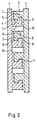
- FIG. 2 two base plates 1 interconnected by coupling means 2 are shown.
- base plate 1 on the right side of the figure is turned upside down and leg 4 of each coupling means 2 occupies the space between leg 3 and leg 4 of another coupling means 2.
- inclined inner surfaces 7 of adjacent legs 4 touches each other, e.g. surface 7 of coupling means 2 of base plate 1 on the right side slides down on surface 7 of coupling means 2 of base plate 1 on the left side.
- base plate 1 on the right side will forcingly move in the direction of base plate 1 on the left side, the outer surface 8 of legs 4 will be pressed against inner surfaces 9 of legs 3.
- top surface 6 of leg 4 is just as big as the distance between legs 3 and 4. If top surface 6 were smaller than the distance between legs 3 and 4, top surface 6 would not touch rib 5 between legs 3 and 4.
- Fig. 3 the building construction assembled from the module elements as shown in Fig. 1 and 2 is illustrated.
- an iron framework 12 is welded together from iron rods as it is usual with ferroconcrete building constructions.
- This framework 12 will be the reinforcement structure of the building. But in this stage, it serves as a holding structure for the module elements.
- the rods of framework 12 are arranged for occupying would- be channels 10 and 11 between coupling means 2 of the module elements.
- the channels 10 and 11 is filled out with concrete.
- framework 9 is removed at the left hand portion of Fig. 3 and the module elements are removed after solidification of the concrete at the right hand portion.
- channels 10 and 11 Before filling out the channels 10 and 11 with concrete, other installational parts of the building such as electrical and electronic conduits, water and gas pipes, spouts etc. can be fixed on framework 12. Furthermore, ventilation channels for heating and/or cooling can be provided in channels 10, 11.
Landscapes
- Engineering & Computer Science (AREA)
- Architecture (AREA)
- Physics & Mathematics (AREA)
- Electromagnetism (AREA)
- Civil Engineering (AREA)
- Structural Engineering (AREA)
- Joining Of Building Structures In Genera (AREA)
- Finishing Walls (AREA)
- Forms Removed On Construction Sites Or Auxiliary Members Thereof (AREA)
Claims (4)
Applications Claiming Priority (2)
| Application Number | Priority Date | Filing Date | Title |
|---|---|---|---|
| HU410783 | 1983-11-30 | ||
| HU834107A HU187614B (en) | 1983-11-30 | 1983-11-30 | Building unit and method for constructing buildings particularly reinforced concrete ones by using of the method |
Publications (2)
| Publication Number | Publication Date |
|---|---|
| EP0165959A1 EP0165959A1 (de) | 1986-01-02 |
| EP0165959B1 true EP0165959B1 (de) | 1988-06-15 |
Family
ID=10966926
Family Applications (1)
| Application Number | Title | Priority Date | Filing Date |
|---|---|---|---|
| EP85900160A Expired EP0165959B1 (de) | 1983-11-30 | 1984-11-30 | Baukonstruktion und verfahren zum errichten eines gebäudes |
Country Status (8)
| Country | Link |
|---|---|
| US (1) | US4631890A (de) |
| EP (1) | EP0165959B1 (de) |
| JP (1) | JPS61500562A (de) |
| AU (1) | AU570293B2 (de) |
| DE (1) | DE3472128D1 (de) |
| HU (1) | HU187614B (de) |
| IT (1) | IT1178648B (de) |
| WO (1) | WO1985002431A1 (de) |
Families Citing this family (10)
| Publication number | Priority date | Publication date | Assignee | Title |
|---|---|---|---|---|
| JP2644196B2 (ja) * | 1994-09-10 | 1997-08-25 | 東洋エクステリア株式会社 | 建築用パネル |
| FR2790777B1 (fr) * | 1999-03-11 | 2001-06-08 | Abriblue | Ensemble a bancher, notamment pour la construction des piscines |
| USD442290S1 (en) | 1999-12-14 | 2001-05-15 | Stefan Erik Aurelius | Paving-stone and a flooring stone |
| USD462785S1 (en) | 2001-07-30 | 2002-09-10 | Erik Stefan Aurelius | Flooring or paving stone |
| US20050066594A1 (en) * | 2003-09-30 | 2005-03-31 | Stavenjord Walter Karl | Casing system |
| WO2009131547A1 (en) * | 2008-04-23 | 2009-10-29 | National University Of Singapore | Composite panel assemblies including separation prevention shear connectors |
| US9238910B2 (en) * | 2008-08-19 | 2016-01-19 | David I. Jensen | Interlocking wall unit system for constructing a wall on a pre-existing structural grid matrix |
| US9091055B2 (en) * | 2008-08-19 | 2015-07-28 | Sonoma Cast Stone Corporation | Wall assembly method |
| CA131569S (en) * | 2009-07-22 | 2010-05-13 | Dan Sims | Precast concrete driveway panel |
| AU2015348437B2 (en) * | 2014-11-17 | 2020-08-06 | Ceramica Malpesa, S.A. | Constructive assembly for building walls |
Citations (1)
| Publication number | Priority date | Publication date | Assignee | Title |
|---|---|---|---|---|
| FR2512479A1 (fr) * | 1981-09-09 | 1983-03-11 | Klein Victor | Element de construction d'une paroi et paroi ainsi construite |
Family Cites Families (13)
| Publication number | Priority date | Publication date | Assignee | Title |
|---|---|---|---|---|
| US679746A (en) * | 1901-04-08 | 1901-08-06 | William H Grueby | Building construction. |
| US1052788A (en) * | 1910-04-06 | 1913-02-11 | Edward T Bates | Composite construction of walls, partitions, and the like. |
| US1535030A (en) * | 1920-11-01 | 1925-04-21 | William E Nelson | Concrete building structure |
| US1585374A (en) * | 1924-11-24 | 1926-05-18 | Carlsson John | Building block |
| US1770082A (en) * | 1929-06-29 | 1930-07-08 | John R Mcpherson | Building unit |
| US2038615A (en) * | 1933-07-28 | 1936-04-28 | Donald G Underdown | Art of construction |
| US2205589A (en) * | 1939-03-15 | 1940-06-25 | Clark Equipment Co | Gear shifting means |
| US2260178A (en) * | 1940-02-05 | 1941-10-21 | Jr Emile S Guignon | Removable panel |
| US2412253A (en) * | 1945-12-17 | 1946-12-10 | Higgins Ind Inc | Wall panel |
| DE817799C (de) * | 1949-06-29 | 1951-10-19 | Heinrich Becker | Aussenwand aus Hohlblocksteinen |
| AT167489B (de) * | 1949-07-27 | 1951-01-10 | Josef Langhans | Hohlbauelement aus Leichtbaustoff, insbesondere Hüttenbimsbeton |
| FR1124806A (fr) * | 1955-05-18 | 1956-10-18 | Aveyronnaise De Const Ind Soc | Parpaing creux à emboîtement et à rupture de joints, assemblage sans liant |
| US4147007A (en) * | 1976-12-10 | 1979-04-03 | Ebco Industries, Ltd. | Matable modular elements for toy, display and model applications utilizing paired rib structure |
-
1983
- 1983-11-30 HU HU834107A patent/HU187614B/hu not_active IP Right Cessation
-
1984
- 1984-11-30 AU AU37499/85A patent/AU570293B2/en not_active Ceased
- 1984-11-30 US US06/770,862 patent/US4631890A/en not_active Expired - Fee Related
- 1984-11-30 EP EP85900160A patent/EP0165959B1/de not_active Expired
- 1984-11-30 JP JP60500053A patent/JPS61500562A/ja active Pending
- 1984-11-30 WO PCT/HU1984/000058 patent/WO1985002431A1/en not_active Ceased
- 1984-11-30 IT IT23815/84A patent/IT1178648B/it active
- 1984-11-30 DE DE8585900160T patent/DE3472128D1/de not_active Expired
Patent Citations (1)
| Publication number | Priority date | Publication date | Assignee | Title |
|---|---|---|---|---|
| FR2512479A1 (fr) * | 1981-09-09 | 1983-03-11 | Klein Victor | Element de construction d'une paroi et paroi ainsi construite |
Also Published As
| Publication number | Publication date |
|---|---|
| DE3472128D1 (en) | 1988-07-21 |
| IT1178648B (it) | 1987-09-09 |
| JPS61500562A (ja) | 1986-03-27 |
| IT8423815A0 (it) | 1984-11-30 |
| WO1985002431A1 (en) | 1985-06-06 |
| AU3749985A (en) | 1985-06-13 |
| AU570293B2 (en) | 1988-03-10 |
| HU187614B (en) | 1986-02-28 |
| IT8423815A1 (it) | 1986-05-30 |
| EP0165959A1 (de) | 1986-01-02 |
| US4631890A (en) | 1986-12-30 |
Similar Documents
| Publication | Publication Date | Title |
|---|---|---|
| KR860004217A (ko) | 조립식 모듈과 그의 조립방법 | |
| US20120311949A1 (en) | Thermal insulated building wall construction method | |
| EP0163117A1 (de) | Modulare Bauelemente mit einer hohen thermischen und/oder akustischen Isolation | |
| AU570293B2 (en) | Building construction formed of module elements (especially walls) | |
| US5802793A (en) | Precast modular keyed building system | |
| EP0374064A1 (de) | Isolierende Verschalung für Betonmauern | |
| EP0061100B1 (de) | Vorgefertigte Strukturen, Verfahren zur Herstellung und ihre Anwendung in industriellen Gebäuden | |
| GB1600045A (en) | Structure made of pre-fabricated elements | |
| EP0558826B1 (de) | Verfahren zur Herstellung eines Deckenelementes oder einer Rippedecken und Wärmedämmplatte für Deckenelementen | |
| CA1295843C (en) | Casing for making concrete construction components | |
| JPH11107440A (ja) | 建築構造物の壁面パネル | |
| EP0383112B1 (de) | Vorgefertigte L-förmige wärmedämmende Wandelemente und rechteckiges Element zum Errichten von Gebäuden | |
| JP3165363B2 (ja) | プレキャストコンクリート床の接合構造 | |
| KR19980019399A (ko) | 건축물 벽체거푸집 조립체 | |
| JP3239867U (ja) | カルバート構造物 | |
| JP2000129692A (ja) | 型枠支持構造 | |
| RU2052041C1 (ru) | Пустотелый армированный блок | |
| JP2847422B2 (ja) | コンクリートブロックの組積工法 | |
| EP0810335B1 (de) | Modularer Bau | |
| JP2001317065A (ja) | 型枠付き鉄筋ユニット及びこれを用いた基礎構築方法 | |
| JPH04319147A (ja) | プレキャストコンクリート板及びプレキャストコンクリート板を使用した壁構造の構築工法 | |
| EP0196342A1 (de) | Modulare vorgefertigte Portalkonstruktion zur Errichtung von Gebäuden | |
| JPS6319661B2 (de) | ||
| JPS5941564A (ja) | 壁式鉄筋コンクリ−ト構造物の配筋工法 | |
| JPS6128784B2 (de) |
Legal Events
| Date | Code | Title | Description |
|---|---|---|---|
| PUAI | Public reference made under article 153(3) epc to a published international application that has entered the european phase |
Free format text: ORIGINAL CODE: 0009012 |
|
| 17P | Request for examination filed |
Effective date: 19850821 |
|
| AK | Designated contracting states |
Designated state(s): BE CH DE FR GB LI LU NL SE |
|
| 17Q | First examination report despatched |
Effective date: 19860919 |
|
| GRAA | (expected) grant |
Free format text: ORIGINAL CODE: 0009210 |
|
| AK | Designated contracting states |
Kind code of ref document: B1 Designated state(s): BE CH DE FR GB LI LU NL SE |
|
| REF | Corresponds to: |
Ref document number: 3472128 Country of ref document: DE Date of ref document: 19880721 |
|
| ET | Fr: translation filed | ||
| PLBE | No opposition filed within time limit |
Free format text: ORIGINAL CODE: 0009261 |
|
| STAA | Information on the status of an ep patent application or granted ep patent |
Free format text: STATUS: NO OPPOSITION FILED WITHIN TIME LIMIT |
|
| 26N | No opposition filed | ||
| EPTA | Lu: last paid annual fee | ||
| PGFP | Annual fee paid to national office [announced via postgrant information from national office to epo] |
Ref country code: CH Payment date: 19941028 Year of fee payment: 11 |
|
| PGFP | Annual fee paid to national office [announced via postgrant information from national office to epo] |
Ref country code: GB Payment date: 19941122 Year of fee payment: 11 |
|
| PGFP | Annual fee paid to national office [announced via postgrant information from national office to epo] |
Ref country code: SE Payment date: 19941129 Year of fee payment: 11 Ref country code: FR Payment date: 19941129 Year of fee payment: 11 |
|
| PGFP | Annual fee paid to national office [announced via postgrant information from national office to epo] |
Ref country code: NL Payment date: 19941130 Year of fee payment: 11 Ref country code: BE Payment date: 19941130 Year of fee payment: 11 |
|
| PGFP | Annual fee paid to national office [announced via postgrant information from national office to epo] |
Ref country code: LU Payment date: 19941201 Year of fee payment: 12 |
|
| PGFP | Annual fee paid to national office [announced via postgrant information from national office to epo] |
Ref country code: DE Payment date: 19941229 Year of fee payment: 11 |
|
| EAL | Se: european patent in force in sweden |
Ref document number: 85900160.4 |
|
| PG25 | Lapsed in a contracting state [announced via postgrant information from national office to epo] |
Ref country code: LI Effective date: 19951130 Ref country code: GB Effective date: 19951130 Ref country code: CH Effective date: 19951130 Ref country code: BE Effective date: 19951130 |
|
| PG25 | Lapsed in a contracting state [announced via postgrant information from national office to epo] |
Ref country code: SE Effective date: 19951201 |
|
| BERE | Be: lapsed |
Owner name: SZOMBATHELYI IMRE Effective date: 19951130 |
|
| PG25 | Lapsed in a contracting state [announced via postgrant information from national office to epo] |
Ref country code: NL Effective date: 19960601 |
|
| REG | Reference to a national code |
Ref country code: CH Ref legal event code: PL |
|
| GBPC | Gb: european patent ceased through non-payment of renewal fee |
Effective date: 19951130 |
|
| PG25 | Lapsed in a contracting state [announced via postgrant information from national office to epo] |
Ref country code: FR Effective date: 19960731 |
|
| NLV4 | Nl: lapsed or anulled due to non-payment of the annual fee |
Effective date: 19960601 |
|
| PG25 | Lapsed in a contracting state [announced via postgrant information from national office to epo] |
Ref country code: DE Effective date: 19960801 |
|
| REG | Reference to a national code |
Ref country code: FR Ref legal event code: ST |
|
| PG25 | Lapsed in a contracting state [announced via postgrant information from national office to epo] |
Ref country code: LU Free format text: LAPSE BECAUSE OF NON-PAYMENT OF DUE FEES Effective date: 19961130 |