EP0166030A1 - Diaphragme pour le rayonnement X primaire d'un appareil de radiodiagnostic pour prises de vue stéréoradiographiques - Google Patents
Diaphragme pour le rayonnement X primaire d'un appareil de radiodiagnostic pour prises de vue stéréoradiographiques Download PDFInfo
- Publication number
- EP0166030A1 EP0166030A1 EP84115579A EP84115579A EP0166030A1 EP 0166030 A1 EP0166030 A1 EP 0166030A1 EP 84115579 A EP84115579 A EP 84115579A EP 84115579 A EP84115579 A EP 84115579A EP 0166030 A1 EP0166030 A1 EP 0166030A1
- Authority
- EP
- European Patent Office
- Prior art keywords
- diaphragm
- parts
- radiation
- focus
- primary beam
- Prior art date
- Legal status (The legal status is an assumption and is not a legal conclusion. Google has not performed a legal analysis and makes no representation as to the accuracy of the status listed.)
- Granted
Links
Images

Classifications
-
- A—HUMAN NECESSITIES
- A61—MEDICAL OR VETERINARY SCIENCE; HYGIENE
- A61B—DIAGNOSIS; SURGERY; IDENTIFICATION
- A61B6/00—Apparatus or devices for radiation diagnosis; Apparatus or devices for radiation diagnosis combined with radiation therapy equipment
- A61B6/02—Arrangements for diagnosis sequentially in different planes; Stereoscopic radiation diagnosis
- A61B6/022—Stereoscopic imaging
-
- A—HUMAN NECESSITIES
- A61—MEDICAL OR VETERINARY SCIENCE; HYGIENE
- A61B—DIAGNOSIS; SURGERY; IDENTIFICATION
- A61B6/00—Apparatus or devices for radiation diagnosis; Apparatus or devices for radiation diagnosis combined with radiation therapy equipment
- A61B6/06—Diaphragms
-
- A—HUMAN NECESSITIES
- A61—MEDICAL OR VETERINARY SCIENCE; HYGIENE
- A61B—DIAGNOSIS; SURGERY; IDENTIFICATION
- A61B6/00—Apparatus or devices for radiation diagnosis; Apparatus or devices for radiation diagnosis combined with radiation therapy equipment
- A61B6/08—Auxiliary means for directing the radiation beam to a particular spot, e.g. using light beams
-
- G—PHYSICS
- G21—NUCLEAR PHYSICS; NUCLEAR ENGINEERING
- G21K—HANDLING OF PARTICLES OR IONISING RADIATION NOT OTHERWISE PROVIDED FOR; IRRADIATION DEVICES; GAMMA RAY OR X-RAY MICROSCOPES
- G21K1/00—Arrangements for handling particles or ionising radiation, e.g. focusing or moderating
- G21K1/02—Arrangements for handling particles or ionising radiation, e.g. focusing or moderating using diaphragms, collimators
Definitions
- the invention relates to a primary radiation diaphragm for an x-ray diagnostic system for x-ray stereo images with an x-ray emitter with two focal points spaced apart from one another.
- the radiographic examination of the examination object takes place from one focus each.
- the viewer By simultaneously viewing two images, each associated with one of the foci, the viewer is given a spatial image impression.
- the problem with a multi-focus x-ray tube is to ensure that for each of the two x-ray beams emitted by the two foci, the radiation of the region of the examination object that is important for the imaging is ensured without more tissue than necessary being penetrated by x-radiation.
- the invention has for its object to provide a primary beam diaphragm of the type mentioned, in which each radiation pyramid is optimally adjustable for each focus, the tip of which coincides with the respective focus.
- diaphragm parts which are adjustable in such a way that a radiation pyramid can be set individually for each focus.
- An expedient development of the invention consists in that for fading in perpendicularly to the stereo base, that is to say the connecting line between the two foci, two inner diaphragm parts, each adjustable in the direction of the respectively adjacent outer diaphragm part, are provided between two outer diaphragm parts.
- the two radiation pyramids can be delimited parallel to the stereo base by means of a pair of diaphragm plates common to both radiation pyramids, while both the outer and the inner diaphragm parts can be adjusted perpendicularly to the stereo base to limit the two radiation pyramids.
- the inner diaphragm parts can be designed in such a way that, when they are adjusted outwards, they release a central radiation pyramid of a medium focus and close the outer diaphragm openings together with the outer diaphragm parts.
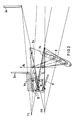
- FIG. 1 shows a primary beam diaphragm which allows three pyramids of radiation emanating from three foci F1, F2 and FN to be faded in.
- the focal points F1 and F2 serve to produce stereo image pairs, while the focal point FN serves to generate a normal x-ray image.
- the fade out parallel to the stereo base, i.e. the distance F1-F2 as with normal primary beam diaphragms, takes place by means of near-focus and far-away aperture plate pairs la, 1b.
- the fading out across the stereo base takes place during stereo operation (alternately switching on the focal points F1, F2) on the outside by the slats 2a close to the focus for the focus F1, 2b for the focus F2 and by the slats 3a and 3b away from the focus.
- the lamellae 2a, 2b and 3a, 3b can be adjusted perpendicular to the respective central beam of the radiation pyramid that is shown in a plane in which the stereo base F1 - F2 lies.
- an inner position is shown in dash-dotted lines.
- the radiation pyramids are delimited on the inside by pivoting shutters 4a for focus F1 and 4b for focus F2.
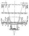
- the swivel screens 4a, 4b can be swiveled about axes 5a, 5b and can also be adjusted parallel to the stereo base on guides 14 (FIG. 3).
- the slats 2a, 2b, 3a, 3b and the swivel panels 4a, 4b are adjusted by a stepper motor, not shown.
- the movement sequence is coordinated by a microcomputer.
- the microcomputer coordinates the aperture movements to a new one Aperture setting.
- the lamellae 2a, 3a and the swivel aperture 4a which limit the radiation pyramid I at the top and bottom in stereo operation according to FIG. 1, together form the upper limit of the radiation pyramid III of the focus FN in normal operation.
- the pivoting panels 4a, 4b are designed in accordance with FIG. 3 so that, in a breakthrough in the area of the axes 5a, 5b, the movement space for the panel plate pairs la, lb and for filter slides 6a, 6b, 6c, 6d remains free.
- the outer boundary surfaces 7a, 7b (FIG. 2) of the swivel screens 4a, 4b act to limit radiation, in normal operation the inner boundary surfaces 8a, 8b.
- the pivoting panels 4a, 4b are pivoted via a link guide 9 according to FIG. 2.
- a light sight 10a, 10b, 10c consisting of a lamp and two mirrors, can be arranged in the space between the swiveling apertures 4a, 4b and the aperture plate pair 1b.
- the installation of an octagon boundary 11 is also possible, which is shown only schematically in the figures.
- a pivoting panel 12 In the space between the pivoting panels 4a, 4b, a pivoting panel 12 according to FIGS. 2 and 3 can be arranged, which is actuated by spring force during stereo operation and small field fade-in, then covers the gap that then opens between the pivoting panels 4a and 4b and thus the leakage of extra -focal radiation prevented.
- the pivoting panel 12 In normal operation, the pivoting panel 12 is held open by a linkage 13 by the lamella 2a then resting on the pivoting panel 4a.
- the diaphragm parts la, lb, 2a, 2b, 3a, 3b and 4a, 4b are designed and adjustable in such a way that a radiation pyramid I, II individually for each focus F1, F2 is adjustable and that for the display perpendicular to the stereo base F1, F2 between two outer panel parts 2a, 2b, two inner panel parts 4a, 4b, each adjustable in the direction of the respectively adjacent outer panel part 2a, 2b, are provided.
- the inner diaphragm parts 4a, 4b are designed such that when they are adjusted outwards they release a middle radiation pyramid III of a middle focus FN and close the outer diaphragm openings for the radiation pyramids I, II together with the outer diaphragm parts 2a, 2b.
- the described primary beam aperture can be used either as a stereo or normal aperture.
Landscapes
- Health & Medical Sciences (AREA)
- Life Sciences & Earth Sciences (AREA)
- Engineering & Computer Science (AREA)
- Medical Informatics (AREA)
- Physics & Mathematics (AREA)
- High Energy & Nuclear Physics (AREA)
- Radiology & Medical Imaging (AREA)
- Molecular Biology (AREA)
- Optics & Photonics (AREA)
- Pathology (AREA)
- Biophysics (AREA)
- Biomedical Technology (AREA)
- Heart & Thoracic Surgery (AREA)
- Nuclear Medicine, Radiotherapy & Molecular Imaging (AREA)
- Surgery (AREA)
- Animal Behavior & Ethology (AREA)
- General Health & Medical Sciences (AREA)
- Public Health (AREA)
- Veterinary Medicine (AREA)
- Spectroscopy & Molecular Physics (AREA)
- General Engineering & Computer Science (AREA)
- Apparatus For Radiation Diagnosis (AREA)
Applications Claiming Priority (2)
| Application Number | Priority Date | Filing Date | Title |
|---|---|---|---|
| DE3422343 | 1984-06-15 | ||
| DE3422343 | 1984-06-15 |
Publications (2)
| Publication Number | Publication Date |
|---|---|
| EP0166030A1 true EP0166030A1 (fr) | 1986-01-02 |
| EP0166030B1 EP0166030B1 (fr) | 1988-08-03 |
Family
ID=6238490
Family Applications (1)
| Application Number | Title | Priority Date | Filing Date |
|---|---|---|---|
| EP84115579A Expired EP0166030B1 (fr) | 1984-06-15 | 1984-12-17 | Diaphragme pour le rayonnement X primaire d'un appareil de radiodiagnostic pour prises de vue stéréoradiographiques |
Country Status (4)
| Country | Link |
|---|---|
| US (1) | US4641335A (fr) |
| EP (1) | EP0166030B1 (fr) |
| JP (1) | JPS6117998A (fr) |
| DE (1) | DE3473197D1 (fr) |
Cited By (1)
| Publication number | Priority date | Publication date | Assignee | Title |
|---|---|---|---|---|
| EP0485998A1 (fr) * | 1990-11-13 | 1992-05-20 | Kabushiki Kaisha Toshiba | Appareil de radiographie |
Families Citing this family (11)
| Publication number | Priority date | Publication date | Assignee | Title |
|---|---|---|---|---|
| US5224145A (en) * | 1990-03-28 | 1993-06-29 | Kabushiki Kaisha Toshiba | X-ray beam limiting apparatus including pivotable blade |
| US5396534A (en) * | 1993-10-12 | 1995-03-07 | Thomas; Howard C. | Shutter apparatus for collimating x-rays |
| SE9401904D0 (sv) * | 1994-06-02 | 1994-06-02 | Siemens Elema Ab | Röntgenundersökningsapparat |
| US6052430A (en) * | 1997-09-25 | 2000-04-18 | Siemens Medical Systems, Inc. | Dynamic sub-space intensity modulation |
| JP2000004865A (ja) * | 1998-06-25 | 2000-01-11 | Yasuyuki Moriyama | シガレットの付属消火装置 |
| DE10162256B4 (de) * | 2001-12-18 | 2004-09-09 | Siemens Ag | Strahlenblende für ein Röntgengerät |
| FR2834179A1 (fr) * | 2001-12-24 | 2003-06-27 | Chabunda Christophe Mwanza | Dispositif de scanographie helicoidale a phases multiples de balayage |
| CN1786819B (zh) * | 2004-12-09 | 2011-08-10 | Ge医疗系统环球技术有限公司 | X射线光阑、x射线辐照器和x射线成像设备 |
| CN101347335B (zh) * | 2007-03-14 | 2010-11-03 | 张迎光 | 能产生立体视觉效果的x射线发生装置及医用x射线设备 |
| WO2012152851A1 (fr) * | 2011-05-10 | 2012-11-15 | Universiteit Gent | Procédés et systèmes pour collimation |
| US12165781B2 (en) * | 2019-03-15 | 2024-12-10 | Robotic Technologies Limited | X-ray imaging system comprising a shutter and method |
Citations (4)
| Publication number | Priority date | Publication date | Assignee | Title |
|---|---|---|---|---|
| DE2744808A1 (de) * | 1976-10-05 | 1978-04-06 | Tokyo Shibaura Electric Co | Roentgenstrahlungsquelle |
| DE2728999A1 (de) * | 1977-06-28 | 1979-01-18 | Philips Patentverwaltung | Zielvorrichtung fuer mehrfachstrahlenquelle |
| EP0027291A1 (fr) * | 1979-10-12 | 1981-04-22 | Philips Patentverwaltung GmbH | Dispositif générateur d'images tomographiques par des expositions multiples en perspective à différents taux de superposition |
| EP0074596A1 (fr) * | 1981-09-16 | 1983-03-23 | Siemens Aktiengesellschaft | Appareil d'examen à rayons X |
Family Cites Families (6)
| Publication number | Priority date | Publication date | Assignee | Title |
|---|---|---|---|---|
| US2214621A (en) * | 1940-09-10 | Le roy | ||
| US25118A (en) * | 1859-08-16 | of otttjmwa | ||
| USRE25118E (en) | 1957-11-26 | 1962-01-30 | X-ray beam | |
| US3683186A (en) * | 1970-03-26 | 1972-08-08 | Schlumberger Technology Corp | Apparatus for inspecting tubular goods using a radiation-focussing device for producing a substantially uniform composite radiation pattern |
| US4246488A (en) * | 1979-03-09 | 1981-01-20 | Picker Corporation | Radiation collimator |
| DE3121324A1 (de) * | 1981-05-29 | 1982-12-16 | Philips Patentverwaltung Gmbh, 2000 Hamburg | Tomosynthesevorrichtung |
-
1984
- 1984-12-17 EP EP84115579A patent/EP0166030B1/fr not_active Expired
- 1984-12-17 DE DE8484115579T patent/DE3473197D1/de not_active Expired
-
1985
- 1985-04-05 US US06/720,321 patent/US4641335A/en not_active Expired - Fee Related
- 1985-06-14 JP JP60129735A patent/JPS6117998A/ja active Granted
Patent Citations (4)
| Publication number | Priority date | Publication date | Assignee | Title |
|---|---|---|---|---|
| DE2744808A1 (de) * | 1976-10-05 | 1978-04-06 | Tokyo Shibaura Electric Co | Roentgenstrahlungsquelle |
| DE2728999A1 (de) * | 1977-06-28 | 1979-01-18 | Philips Patentverwaltung | Zielvorrichtung fuer mehrfachstrahlenquelle |
| EP0027291A1 (fr) * | 1979-10-12 | 1981-04-22 | Philips Patentverwaltung GmbH | Dispositif générateur d'images tomographiques par des expositions multiples en perspective à différents taux de superposition |
| EP0074596A1 (fr) * | 1981-09-16 | 1983-03-23 | Siemens Aktiengesellschaft | Appareil d'examen à rayons X |
Cited By (2)
| Publication number | Priority date | Publication date | Assignee | Title |
|---|---|---|---|---|
| EP0485998A1 (fr) * | 1990-11-13 | 1992-05-20 | Kabushiki Kaisha Toshiba | Appareil de radiographie |
| US5237599A (en) * | 1990-11-13 | 1993-08-17 | Kabushiki Kaisha Toshiba | X-ray apparatus |
Also Published As
| Publication number | Publication date |
|---|---|
| JPS6117998A (ja) | 1986-01-25 |
| DE3473197D1 (en) | 1988-09-08 |
| JPH0528360B2 (fr) | 1993-04-26 |
| EP0166030B1 (fr) | 1988-08-03 |
| US4641335A (en) | 1987-02-03 |
Similar Documents
| Publication | Publication Date | Title |
|---|---|---|
| DE69120897T2 (de) | Röntgeneinrichtung | |
| EP0166030B1 (fr) | Diaphragme pour le rayonnement X primaire d'un appareil de radiodiagnostic pour prises de vue stéréoradiographiques | |
| EP0127073B1 (fr) | Appareil de diagnostic pour prise de radiographies mammaires | |
| DE69411235T2 (de) | Weichgewebe Filtergerät für einen Kephalostat | |
| DE202019106995U1 (de) | Röntgen-Kollimator mit Haupt- und Nebenuntersuchungsbereich | |
| DE7710947U1 (de) | Röntgenuntersuchungsgerät | |
| DE3138939A1 (de) | Roentgenuntersuchungsgeraet | |
| EP0074596A1 (fr) | Appareil d'examen à rayons X | |
| DE2847011C2 (de) | Vorrichtung zur Erzeugung von Schichtbildern eines dreidimensionalen Körpers | |
| EP0980671A1 (fr) | Appareil de radiodiagnostic avec une unité d'ouverture | |
| DE19634066C2 (de) | Katapultrasterlade eines Röntgendiagnostikgerätes | |
| EP0103794B1 (fr) | Diaphragme pour un appareil d'examen à rayons X | |
| DE4143221A1 (de) | Optisches system fuer einen projektor | |
| DE2239003B2 (de) | Vorrichtung zur allseitigen Röntgenprfifung eines drehbar abgestützten Kraftfahrzeugreifens | |
| DE2145729C3 (de) | Projektionsvorrichtung | |
| EP0089094B1 (fr) | Appareil avec diaphragme d'objectif radiographique et avec un dispositif pour prise de vue en surimpression proche de l'image | |
| EP0184695A1 (fr) | Diaphragme pour rayonnement primaire dans un appareil d'examen radiologique | |
| DE102005028904B4 (de) | Röntgenstrahlenerzeuger für ein Röntgengerät mit Röntgenlinsenmodul | |
| DE202023103001U1 (de) | Kollimator für eine Röntgenstrahlung | |
| DE8418233U1 (de) | Primärstrahlenblende für eine Röntgendiagnostikanlage für Röntgen-Stereobilder | |
| EP0100562B1 (fr) | Appareil pour la réalisation d'images radiographiques de corps | |
| DE102018221559B4 (de) | Tomosyntheseeinrichtung mit einem bewegten Röntgenstrahler | |
| WO1996027144A1 (fr) | Systeme d'ecran autostereoscopique | |
| DE102004012050B4 (de) | Blendeneinheit und zugeordneter Röntgenstrahler bzw. Verfahren zu deren Verstellung zum Einblenden eines Untersuchungsbereiches bzw. Röntgeneinrichtung | |
| DE453447C (de) | Durchleuchtungs- und Aufnahme-Blende fuer die Orthodiagraphie |
Legal Events
| Date | Code | Title | Description |
|---|---|---|---|
| PUAI | Public reference made under article 153(3) epc to a published international application that has entered the european phase |
Free format text: ORIGINAL CODE: 0009012 |
|
| AK | Designated contracting states |
Designated state(s): DE FR |
|
| 17P | Request for examination filed |
Effective date: 19860128 |
|
| 17Q | First examination report despatched |
Effective date: 19870406 |
|
| GRAA | (expected) grant |
Free format text: ORIGINAL CODE: 0009210 |
|
| AK | Designated contracting states |
Kind code of ref document: B1 Designated state(s): DE FR |
|
| REF | Corresponds to: |
Ref document number: 3473197 Country of ref document: DE Date of ref document: 19880908 |
|
| ET | Fr: translation filed | ||
| PLBE | No opposition filed within time limit |
Free format text: ORIGINAL CODE: 0009261 |
|
| STAA | Information on the status of an ep patent application or granted ep patent |
Free format text: STATUS: NO OPPOSITION FILED WITHIN TIME LIMIT |
|
| 26N | No opposition filed | ||
| PGFP | Annual fee paid to national office [announced via postgrant information from national office to epo] |
Ref country code: FR Payment date: 19931223 Year of fee payment: 10 |
|
| PGFP | Annual fee paid to national office [announced via postgrant information from national office to epo] |
Ref country code: DE Payment date: 19950217 Year of fee payment: 11 |
|
| PG25 | Lapsed in a contracting state [announced via postgrant information from national office to epo] |
Ref country code: FR Effective date: 19950831 |
|
| REG | Reference to a national code |
Ref country code: FR Ref legal event code: ST |
|
| PG25 | Lapsed in a contracting state [announced via postgrant information from national office to epo] |
Ref country code: DE Effective date: 19960903 |