EP0166064A1 - Trennschleifmaschine mit einer Messanordnung und Verwendung dieser Messanordnung - Google Patents
Trennschleifmaschine mit einer Messanordnung und Verwendung dieser Messanordnung Download PDFInfo
- Publication number
- EP0166064A1 EP0166064A1 EP84810317A EP84810317A EP0166064A1 EP 0166064 A1 EP0166064 A1 EP 0166064A1 EP 84810317 A EP84810317 A EP 84810317A EP 84810317 A EP84810317 A EP 84810317A EP 0166064 A1 EP0166064 A1 EP 0166064A1
- Authority
- EP
- European Patent Office
- Prior art keywords
- cutting
- measuring
- arrangement according
- workpiece
- guide table
- Prior art date
- Legal status (The legal status is an assumption and is not a legal conclusion. Google has not performed a legal analysis and makes no representation as to the accuracy of the status listed.)
- Granted
Links
- 238000005520 cutting process Methods 0.000 title claims abstract description 89
- 238000005259 measurement Methods 0.000 claims abstract description 16
- 239000000463 material Substances 0.000 claims description 7
- 230000005484 gravity Effects 0.000 claims description 2
- 230000001939 inductive effect Effects 0.000 claims description 2
- 238000000034 method Methods 0.000 claims 1
- 230000003287 optical effect Effects 0.000 claims 1
- 230000008859 change Effects 0.000 description 5
- 238000005452 bending Methods 0.000 description 3
- 230000008901 benefit Effects 0.000 description 3
- 238000003745 diagnosis Methods 0.000 description 3
- 230000035945 sensitivity Effects 0.000 description 3
- 238000013461 design Methods 0.000 description 2
- 238000006073 displacement reaction Methods 0.000 description 2
- 238000011156 evaluation Methods 0.000 description 2
- 238000012544 monitoring process Methods 0.000 description 2
- 230000003321 amplification Effects 0.000 description 1
- 230000033228 biological regulation Effects 0.000 description 1
- 239000011248 coating agent Substances 0.000 description 1
- 238000000576 coating method Methods 0.000 description 1
- 230000007423 decrease Effects 0.000 description 1
- 229910003460 diamond Inorganic materials 0.000 description 1
- 239000010432 diamond Substances 0.000 description 1
- 230000000694 effects Effects 0.000 description 1
- 230000007613 environmental effect Effects 0.000 description 1
- 230000002349 favourable effect Effects 0.000 description 1
- 235000015095 lager Nutrition 0.000 description 1
- 238000003754 machining Methods 0.000 description 1
- 238000004519 manufacturing process Methods 0.000 description 1
- 230000007246 mechanism Effects 0.000 description 1
- 229910021421 monocrystalline silicon Inorganic materials 0.000 description 1
- 238000003199 nucleic acid amplification method Methods 0.000 description 1
- 230000036316 preload Effects 0.000 description 1
- 238000012545 processing Methods 0.000 description 1
- 230000001681 protective effect Effects 0.000 description 1
- 230000001105 regulatory effect Effects 0.000 description 1
- 230000000284 resting effect Effects 0.000 description 1
- 239000000523 sample Substances 0.000 description 1
- 239000004065 semiconductor Substances 0.000 description 1
- 238000000926 separation method Methods 0.000 description 1
- 230000003068 static effect Effects 0.000 description 1
- 230000007704 transition Effects 0.000 description 1
- 238000010792 warming Methods 0.000 description 1
Images

Classifications
-
- B—PERFORMING OPERATIONS; TRANSPORTING
- B28—WORKING CEMENT, CLAY, OR STONE
- B28D—WORKING STONE OR STONE-LIKE MATERIALS
- B28D5/00—Fine working of gems, jewels, crystals, e.g. of semiconductor material; apparatus or devices therefor
- B28D5/02—Fine working of gems, jewels, crystals, e.g. of semiconductor material; apparatus or devices therefor by rotary tools, e.g. drills
- B28D5/022—Fine working of gems, jewels, crystals, e.g. of semiconductor material; apparatus or devices therefor by rotary tools, e.g. drills by cutting with discs or wheels
- B28D5/024—Fine working of gems, jewels, crystals, e.g. of semiconductor material; apparatus or devices therefor by rotary tools, e.g. drills by cutting with discs or wheels with the stock carried by a movable support for feeding stock into engagement with the cutting blade, e.g. stock carried by a pivoted arm or a carriage
-
- B—PERFORMING OPERATIONS; TRANSPORTING
- B23—MACHINE TOOLS; METAL-WORKING NOT OTHERWISE PROVIDED FOR
- B23D—PLANING; SLOTTING; SHEARING; BROACHING; SAWING; FILING; SCRAPING; LIKE OPERATIONS FOR WORKING METAL BY REMOVING MATERIAL, NOT OTHERWISE PROVIDED FOR
- B23D59/00—Accessories specially designed for sawing machines or sawing devices
- B23D59/001—Measuring or control devices, e.g. for automatic control of work feed pressure on band saw blade
-
- B—PERFORMING OPERATIONS; TRANSPORTING
- B23—MACHINE TOOLS; METAL-WORKING NOT OTHERWISE PROVIDED FOR
- B23Q—DETAILS, COMPONENTS, OR ACCESSORIES FOR MACHINE TOOLS, e.g. ARRANGEMENTS FOR COPYING OR CONTROLLING; MACHINE TOOLS IN GENERAL CHARACTERISED BY THE CONSTRUCTION OF PARTICULAR DETAILS OR COMPONENTS; COMBINATIONS OR ASSOCIATIONS OF METAL-WORKING MACHINES, NOT DIRECTED TO A PARTICULAR RESULT
- B23Q15/00—Automatic control or regulation of feed movement, cutting velocity or position of tool or work
- B23Q15/007—Automatic control or regulation of feed movement, cutting velocity or position of tool or work while the tool acts upon the workpiece
- B23Q15/12—Adaptive control, i.e. adjusting itself to have a performance which is optimum according to a preassigned criterion
-
- B—PERFORMING OPERATIONS; TRANSPORTING
- B23—MACHINE TOOLS; METAL-WORKING NOT OTHERWISE PROVIDED FOR
- B23Q—DETAILS, COMPONENTS, OR ACCESSORIES FOR MACHINE TOOLS, e.g. ARRANGEMENTS FOR COPYING OR CONTROLLING; MACHINE TOOLS IN GENERAL CHARACTERISED BY THE CONSTRUCTION OF PARTICULAR DETAILS OR COMPONENTS; COMBINATIONS OR ASSOCIATIONS OF METAL-WORKING MACHINES, NOT DIRECTED TO A PARTICULAR RESULT
- B23Q17/00—Arrangements for observing, indicating or measuring on machine tools
- B23Q17/09—Arrangements for observing, indicating or measuring on machine tools for indicating or measuring cutting pressure or for determining cutting-tool condition, e.g. cutting ability, load on tool
-
- B—PERFORMING OPERATIONS; TRANSPORTING
- B24—GRINDING; POLISHING
- B24B—MACHINES, DEVICES, OR PROCESSES FOR GRINDING OR POLISHING; DRESSING OR CONDITIONING OF ABRADING SURFACES; FEEDING OF GRINDING, POLISHING, OR LAPPING AGENTS
- B24B49/00—Measuring or gauging equipment for controlling the feed movement of the grinding tool or work; Arrangements of indicating or measuring equipment, e.g. for indicating the start of the grinding operation
- B24B49/16—Measuring or gauging equipment for controlling the feed movement of the grinding tool or work; Arrangements of indicating or measuring equipment, e.g. for indicating the start of the grinding operation taking regard of the load
-
- B—PERFORMING OPERATIONS; TRANSPORTING
- B28—WORKING CEMENT, CLAY, OR STONE
- B28D—WORKING STONE OR STONE-LIKE MATERIALS
- B28D5/00—Fine working of gems, jewels, crystals, e.g. of semiconductor material; apparatus or devices therefor
- B28D5/02—Fine working of gems, jewels, crystals, e.g. of semiconductor material; apparatus or devices therefor by rotary tools, e.g. drills
- B28D5/022—Fine working of gems, jewels, crystals, e.g. of semiconductor material; apparatus or devices therefor by rotary tools, e.g. drills by cutting with discs or wheels
- B28D5/028—Fine working of gems, jewels, crystals, e.g. of semiconductor material; apparatus or devices therefor by rotary tools, e.g. drills by cutting with discs or wheels with a ring blade having an inside cutting edge
-
- Y—GENERAL TAGGING OF NEW TECHNOLOGICAL DEVELOPMENTS; GENERAL TAGGING OF CROSS-SECTIONAL TECHNOLOGIES SPANNING OVER SEVERAL SECTIONS OF THE IPC; TECHNICAL SUBJECTS COVERED BY FORMER USPC CROSS-REFERENCE ART COLLECTIONS [XRACs] AND DIGESTS
- Y10—TECHNICAL SUBJECTS COVERED BY FORMER USPC
- Y10T—TECHNICAL SUBJECTS COVERED BY FORMER US CLASSIFICATION
- Y10T82/00—Turning
- Y10T82/16—Severing or cut-off
- Y10T82/16032—Automatic and/or triggered control
-
- Y—GENERAL TAGGING OF NEW TECHNOLOGICAL DEVELOPMENTS; GENERAL TAGGING OF CROSS-SECTIONAL TECHNOLOGIES SPANNING OVER SEVERAL SECTIONS OF THE IPC; TECHNICAL SUBJECTS COVERED BY FORMER USPC CROSS-REFERENCE ART COLLECTIONS [XRACs] AND DIGESTS
- Y10—TECHNICAL SUBJECTS COVERED BY FORMER USPC
- Y10T—TECHNICAL SUBJECTS COVERED BY FORMER US CLASSIFICATION
- Y10T83/00—Cutting
- Y10T83/141—With means to monitor and control operation [e.g., self-regulating means]
- Y10T83/148—Including means to correct the sensed operation
Definitions
- the present invention relates to a measuring arrangement on a cut-off machine, in particular on an internal cutting saw, for detecting the cutting forces acting on the material to be cut by a cutting tool, the material to be cut being mounted on a movable holder, and at least one measuring transducer being provided for measuring the cutting forces.
- Such cutting machines in particular internal saws, are used for cutting brittle, hard materials, such as semiconductor materials, e.g. monocrystalline silicon. They offer the advantage that high precision with regard to parallelism, flatness and thickness tolerance is achieved with minimal cutting losses.
- a prerequisite for these advantages, however, is constant monitoring of the cutting process with suitable, reliable measuring devices. For example, it is known to detect the deflection of the inner cutting disc and, if the deflection is too high, to take measures, in particular to retighten or pull off the inner cutting disc (EPA No. 83810494.1).
- the rod-shaped workpiece to be cut into slices is fastened to a rod end in a known manner with a support strip and is arranged in a self-supporting manner.
- a measuring transducer is installed between this fastening part of the rod and a workpiece carrier block that can be moved in the direction of the rod axis. In this case it is difficult to find a sufficiently stable one To achieve holder of the workpiece.
- the measuring transducer is arranged in the plane of the cutting disc and the support strip, to which the rod to be cut into pieces is glued, lies directly on the measuring transducer. The accuracy of such a measurement strongly depends on how the end of the rod is clamped on its workpiece carrier block, and it is therefore very difficult to achieve the same conditions again and again. A new calibration is therefore required for each new rod used.
- a precise measurement of the cutting forces also requires a very precise parallelism of the underside of the support bar resting on the transducer to the direction of displacement (infeed direction) of the workpiece and absolute flatness. Since both conditions can hardly be met, large tolerances regarding parallelism and thickness of the disks occur when the workpiece is brought in. Depending on the design options of the flexible workpiece clamping point, there is also a different, permanent influence on the cutting force measurement results.
- the aim of the invention is to provide a simple measuring arrangement that is insensitive to harsh environmental conditions, which in no way complicates the design of the workpiece infeed, stable clamping and support of the workpiece, and allows any orientation of the workpiece in horizontal and vertical direction that does not influence the measurement .
- This goal is achieved in that the transducer to the Er grasp the deformation of a machine part carrying the workpiece carrier block is arranged. This results in a complete separation of the area of the workpiece holder and the cutting force measurement, with which problem-free use is achieved, even in 24-hour production, with minimal demands on the operating personnel.
- a special, elastically deformable measuring part is preferably installed between a machine part which receives the workpiece carrier block and a slide which generates the cutting feed movement or a stationary carrier.
- the invention also relates to an application of the measuring arrangement described above in an internal cutting saw, which is characterized in that, in addition to the cutting force, the cutting disk deflection is detected and the cutting process is controlled and / or a diagnosis is made on the basis of both results.
- the combination of both measurement results allows further conclusions to be drawn, in particular with regard to the condition of the cutting disc, which enables optimal control and diagnosis.
- the cutting disc 1 has already partially penetrated a rod-shaped workpiece 7 and has thus partially cut one of the discs 8 to be produced.
- the cutting disc 1 acts with a cutting force F on the machining point in the workpiece 7.
- the workpiece is glued to a support bar or saw support 9.
- the workpiece 7 is also glued to a plate 11 of a workpiece carrier block 12, which advances the workpiece by one sub-step after each cutting operation, i.e. allowed to shift to the right in Figure 1 to bring it into position to make the next cut.
- the workpiece support block 12 and the saw support 9 rest on a guide table 10.
- the workpiece 7 or the workpiece support block 12 is clamped to the guide table 10 during the cutting process.
- the guide table 10 is rigidly connected to a plate 13.
- spindles or similar adjusting means can be arranged between the guide table 10 and the plate 13 around the guide table 10, and thus the workpiece 7, with respect to the Level of the cutting disc 1 in a very specific angular position bring to.
- These possible setting means are not shown for the sake of simplicity, since they have nothing to do with the measuring device according to the invention, ie their presence does not influence the measuring device, and conversely the setting is not influenced by the measuring device.
- the plate 13 is screwed with eyes 14a to precisely machined bearing surfaces of a vertical slide 14 by means of screws 15.
- the contact surfaces of parts 13 and 14a, as well as the screw forces, are dimensioned to achieve a certain high transition stability of this connection point.
- On the side of the carriage 14 facing the cutting disc 1, the latter has a projecting ledge 16 with raised supports 16a at both ends.
- a measuring rod 17 lies on the supports 16a, the center of which is firmly screwed to the plate 13 by means of a screw 18.
- An intermediate layer 19 precisely determines the contact point and contact surface between the plate 13 and the measuring rod 17.
- the measuring rod is also firmly screwed to the two supports 16a by means of screws 20.
- a measuring transducer 21 is inserted in a hole in the middle of the strip 16 and secured by means of nuts 22 in a position for which the upper end face of the transducer lies at a suitable distance from the measuring rod 17. It is preferably a non-contact displacement transducer which works according to the eddy current measuring principle and is connected to a measuring circuit which has an oscillator for feeding the transducer 21 and an evaluation circuit, for example a demodulator with linearization and amplification. The output signal supplied by this measuring circuit is linear to the cutting force F within certain limits. This cutting force acts on the plate 13 via the guide table 10 and causes a certain measurable change in the deformation of that which is connected to this plate Measuring rod 17.
- the somewhat greater or weaker deflection of the measuring rod 17, depending on the cutting force, has an effect on the measuring transducer 21, so that with appropriate calibration it is possible to measure the cutting force with sufficient accuracy.
- the output signal of the measuring circuit can be used for a digital or analog display as well as for a recording device or an evaluation for the control or regulation of machine functions.
- the rigidity of the connection of the plate 13 to the slide 14, the rigidity of the measuring rod 17, the distance of the measuring rod or transducer from the connection point of the plate 13 and the slide 14, and the position of all these parts with respect to the cutting plane are such that For a cutting force of 10N in the plane of the cutting disc 1, a deflection of, for example, 0.2-0.6 ⁇ m, preferably 0.4 ⁇ m, arises.
- the measuring rod is preferably arranged as close as possible to the plane in which the cutting disc 1 is arranged.
- the position of the connection point between the plate 13 and the slide 14, in the direction of the rod axis of the workpiece 7, is preferably chosen so that this point is located approximately below the center of gravity of the parts including the workpiece built thereon.
- the setting mechanism for the guide table 10 which is located essentially on the left-hand side with respect to FIG. 1, is not shown in FIG. 1.
- the change in the bending moment acting at the connection point between the plate 13 and the slide 14, or the change in the bending moment acting on the measuring rod 17, is thus largely determined by the cutting force F, which has a favorable influence on the accuracy and sensitivity of the measurement.
- a weight of 10N for example, can be attached to the workpiece rod in the cutting plane.
- the measuring device previously set to zero now shows the measured value for this weight.
- the sensitivity can now be set so that the standard force of, for example, 10N results in a specific deflection of, for example, 4 mm on a recording device.
- a re-calibration of the device would be necessary, for example, if the measuring part, consisting of the plate 13, the measuring rod 17 and the screw connections with the slide 14, were removed and reassembled. In this case, the bending stiffness of the screw connections would very likely be changed, which requires re-calibration.
- transducers can be used, for example strain gauges attached to the measuring rod 17 or an inductive measuring probe which is mounted in the strip 16 and touches the measuring rod 17 in the middle for measuring the change in the deflection.
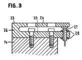
- FIG. 3 Another variant of the measuring part is shown in FIG. 3.
- a tuning fork-like measuring plate 23 with plate-shaped legs 24 and 25 and a yoke 26 connecting these legs is made in one piece.
- the lower leg 25 is screwed to the flat top of the carriage 14.
- the guide table 10 is mounted on the upper leg in a manner not shown.
- a piezoelectric transducer 27 is inserted between the cantilevered ends of the legs 24 and 25 without play and under a certain preload and is secured by means of nuts 28.
- the feed movement of the slide 14 can be regulated so that a constant cutting force or a cutting force that follows a certain predetermined function occurs during each cutting process.
- the cutting force measurement can also only be used for monitoring by automatically or manually intervening when extremely high or low cutting forces occur.
- a particularly advantageous application is to record the cutting wheel deflection in addition to the cutting force in order to control the cutting process and / or to make a diagnosis on the basis of both results.
- a further advantage can arise in this application from the fact that identical measuring transducers are used to deflect the measuring rod 17 or the measuring part 23 and the deflection of the cutting disc 1 detect by then parts of the measuring circuit, such as the oscillator, can be used together to operate both transducers.
- the elastically deformable measuring part can preferably be arranged between the guide table 10 and a carrier of the machine bed that is stationary during processing, or between the cutting disc bearing and a feed slide carrying the same.
Landscapes
- Engineering & Computer Science (AREA)
- Mechanical Engineering (AREA)
- Processing Of Stones Or Stones Resemblance Materials (AREA)
- Finish Polishing, Edge Sharpening, And Grinding By Specific Grinding Devices (AREA)
- Constituent Portions Of Griding Lathes, Driving, Sensing And Control (AREA)
- Length Measuring Devices With Unspecified Measuring Means (AREA)
- Sawing (AREA)
Abstract
Description
- Die vorliegende Erfindung betrifft eine Messanordnung an einer Trennschleifmaschine, insbesondere an einer Innentrennsäge, zur Erfassung der von einem Schnittwerkzeug auf das Schnittgut wirkenden Schnittkräfte, wobei das Schnittgut auf einem beweglichen Halter angebracht ist, und wobei mindestens ein Messwandler zur Messung der Schnittkräfte vorgesehen ist. Solche Trennmaschinen, insbesondere Innentrennsägen, werden eingesetzt zum Trennen von spröden, harten Materialien, wie Halbleitermaterialien, z.B. monokristallinem Silicium. Sie bieten den Vorteil, dass bei minimalen Schnittverlusten hohe Präzision bezüglich Parallelität, Ebenheit und Dickentoleranz erzielt wird. Voraussetzung für diese Vorteile ist jedoch eine dauernde Ueberwachung des Schnittprozesses mit geeigneten zuverlässigen Messvorrichtungen. So ist es beispielsweise bekannt, die Auslenkung der Innentrennscheibe zu erfassen und bei zu hoher Auslenkung Massnahmen zu ergreifen, insbesondere die Innentrennscheibe nachzuspannen oder abzuziehen (EPA Nr. 83810494.1).
- Es ist ebenfalls bekannt, die von der Innentrennscheibe auf das Schnittgut wirkende Schnittkraft zu messen und in Abhängigkeit der gemessenen Schnittkraft die Schnittvorschubgeschwindigkeit zu regeln und/oder ein Abziehen der Innentrennscheibe durchzuführen. Aus der US-PS 4 228 782 sind Vorrichtungen zur Erfassung der Schnittkraft bekannt. In einem Falle ist das in Scheiben zu zerschneidende stabförmige Werkstück mit einer Stützleiste an einem Stabende in bekannter Weise befestigt und freitragend angeordnet. Zwischen dieser Befestigungspartie des Stabes und einem in Stabachsenrichtung verschiebbaren Werkstückträgerblock ist ein Messwandler eingebaut. Es ist in diesem Falle schwierig, eine genügend stabile Halterung des Werkstückes zu erzielen. Da der Abstand der Schnittstelle vom Messwandler bei der Ausführung aufeinanderfolgender Schnitte abnimmt, muss streng genommen für jede Messung eine neue Eichung erfolgen, oder es müssen Mess-Steuersysteme eingesetzt werden, welche den jeweils aktuellen Abstand zwischen Schnitt- und Messstelle berücksichtigen. Aus diesen Gründen können nur Stäbe beschränkter Länge bearbeitet werden. Bei einer anderen Ausführung ist der Messwandler in der Ebene der Trennscheibe angeordnet und die Stützleiste, auf welche der in Scheiben zu zerschneidende Stab aufgeklebt ist, liegt direkt auf dem Messwandler auf. Die Genauigkeit einer solchen Messung ist stark davon abhängig, wie die Einspannung des Stabendes an seinem Werkstücksträgerblock erfolgt, und es ist somit sehr schwierig, immer wieder gleiche Verhältnisse zu erzielen. Es ist daher eine neue Eichung für jeden neu eingesetzten Stab erforderlich. Eine genaue Messung der Schnittkräfte setzt im übrigen eine sehr genaue Parallelität der auf dem Messwandler aufliegenden Unterseite der Stützleiste zur Verschieberichtung (Zustellrichtung) des Werkstückes und absolute Ebenheit voraus. Da beide Bedingungen kaum zu erfüllen sind, treten durch das Zustellen des Werkstükkes grosse Toleranzen bezüglich Parallelität und Dicke der Scheiben auf. Je nach Auslegungsmöglichkeiten der flexiblen Werkstückeinspannstelle besteht zudem eine unterschiedliche, dauernde Beeinflussung der Schnittkraftmessresultate.
- Ziel der Erfindung ist es, eine einfache, gegenüber rauhen Umgebungsbedingungen unempfindliche Messanordnung zu schaffen, welche in keiner Weise die Auslegung der Werkstückzustellung, stabilen Einspannung und Auflage des Werkstückes erschwert, sowie eine die Messung nicht beeinflussende beliebige Orientierung des Werkstücks in horizontaler und vertikaler Richtung erlaubt. Dieses Ziel wird dadurch erreicht, dass der Messwandler zum Erfassen der Verformung eines den Werkstückträgerblock tragenden Maschinenteils angeordnet ist. Es erfolgt damit eine vollständige Trennung des Bereiches der Werkstückaufnahme und der Schnittkraftmessung, womit eine problemlose Anwendung, auch im 24-Stunden-Produktionsbetrieb, bei minimalen Anforderungen an das Bedienungspersonal, erreicht wird.
- Vorzugsweise wird ein besonderer, elastisch verformbarer Messteil zwischen einem Maschinenteil, welches den Werkstückträgerblock aufnimmt und einen die Schnittvorschubbewegung erzeugenden Schlitten oder einen ortsfesten Träger eingebaut.
- Die Erfindung betrifft auch eine Anwendung der oben umschriebenen Messanordnung bei einer Innentrennsäge, welche dadurch gekennzeichnet ist, dass ausser der Schnittkraft die Trennscheibenauslenkung erfasst, und anhand beider Ergebnisse der Schnittvorgang gesteuert und/oder eine Diagnose gestellt wird. Die Kombination beider Messergebnisse lässt weitergehende Schlüsse, insbesondere hinsichtlich des Zustandes der Trennscheibe zu, was eine optimale Steuerung und Diagnose erlaubt.
- Die Erfindung wird nun anhand eines Ausführungsbeispieles und einer Ausführungsvariante, die in der Zeichnung dargestellt sind, näher erläutert.
-
- Figur 1 zeigt einen Vertikalschnitt durch das Ausführungsbeispiel,
- Figur 2 zeigt eine Draufsicht auf den eigentlichen Messteil der Anordnung und
- Figur 3 zeigt schematisch eine Ausführungsvariante des Messteils.
- Gemäss Figur 1 ist die Trennscheibe 1 schon teilweise in ein stabförmiges Werkstück 7 eingedrungen und hat damit eine der herzustellen Scheiben 8 teilweise freigeschnitten. Die Trennscheibe 1 wirkt mit einer Schnittkraft F auf die Bearbeitungsstelle im Werkstück 7. Das Werkstück ist mit einer Stützleiste oder Sägeunterlage 9 verklebt. Das Werkstück 7 ist auch mit einem Teller 11 eines Werkstück-Trägerblockes 12 verklebt, welcher das Werkstück nach je einem Schnittvorgang um einen Teilschritt zuzustellen, d.h. in Figur 1 nach rechts zu verschieben gestattet, um es in die Position zur Ausführung des nächsten Schnittes zu bringen. Der Werkstück-Trägerblock 12 sowie die Sägeunterlage 9 liegen auf einem Führungstisch 10 auf. Je nach Ausführungsart des Zustellsystemes wird das Werkstück 7 oder der Werkstück-Trägerblock 12 während des Trennvorganges mit dem Führungstisch 10 geklemmt.
- Beim Ausführungsbeispiel nach Figur 1 ist angenommen, der Führungstisch 10 sei starr verbunden mit einer Platte 13. Tatsächlich können aber zwischen dem Führungstisch 10 und der Platte 13 Spindeln oder dergleichen Einstellmittel angeordnet sein, um den Führungstisch 10, und damit das Werkstück 7, bezüglich der Ebene der Trennscheibe 1 in eine ganz bestimmte Winkelstellung zu bringen. Diese eventuellen Einstellmittel sind der Einfachheit halber nicht dargestellt, da sie mit der erfindungsgemässen Messvorrichtung nichts zu tun haben, d.h. ihre Anwesenheit beeinflusst die Messeinrichtung nicht, und umgekehrt wird die Einstellung durch die Messvorrichtung nicht beeinflusst.
- Die Platte 13 ist mit Augen 14a mit genau bearbeiteten Auflageflächen eines Vertikalschlittens 14 mittels Schrauben 15 verschraubt. Die Auflageflächen der Teile 13 und 14a, sowie die Schraubenkräfte, sind zur Erzielung einer bestimmten hohen Uebergangsstabilität dieser Verbindungsstelle bemessen. An der der Trennscheibe 1 zugewandten Seite des Schlittens 14 weist derselbe eine vorstehende Leiste 16 mit erhöhten Auflagern 16a an beiden Enden auf. Auf den Auflagern 16a liegt ein Messstab 17, dessen Mitte mittels einer Schraube 18 mit der Platte 13 fest verschraubt ist. Eine Zwischenlage 19 bestimmt genau die Auflagestelle und Auflagefläche zwischen der Platte 13 und dem Messstab 17. Der Messstab ist auch mit den beiden Auflagern 16a fest verschraubt, und zwar mittels Schrauben 20. In einer Bohrung in der Mitte der Leiste 16 ist ein Messwandler 21 eingesetzt und mittels Muttern 22 in einer Lage gesichert, für welche die obere Stirnseite des Messwandlers in geeignetem Abstand vom Messstab 17 liegt. Es handelt sich vorzugsweise um einen berührungslosen Wegaufnehmer, welcher nach dem Wirbelstrom-Messprinzip arbeitet und mit einer Messschaltung verbunden ist, welche einen Oszillator zur Speisung des Messwandlers 21 sowie eine Auswerteschaltung, beispielsweise einen Demodulator mit Linearisierung und Verstärkung, aufweist. Das von dieser Messschaltung gelieferte Ausgangssignal ist innerhalb bestimmter Grenzen linear zur Schnittkraft F. Diese Schnittkraft wirkt nämlich über den Führungstisch 10 auf die Platte 13 und bewirkt eine gewisse messbare Aenderung der Verformung des mit dieser Platte verbundenen Messstabes 17. Die je nach Schnittkraft etwas stärkere oder schwächere Durchbiegung des Messstabes 17 wirkt sich auf den Messwandler 21 aus, so dass mit entsprechender Eichung eine genügend genaue Messung der Schnittkraft möglich ist. Das Ausgangssignal der Messschaltung kann verwendet werden für eine digitale oder analoge Anzeige sowie für ein Aufzeichnungsgerät oder eine Auswertung für die Steuerung oder Regelung von Maschinenfunktionen. Die Steifigkeit der Verbindung der Platte 13 mit dem Schlitten 14, die Steifigkeit des Messstabes 17, der Abstand des Messstabes, beziehungsweise Messwandlers von der Verbindungsstelle der Platte 13 und des Schlittes 14, sowie die Lage all dieser Teile bezüglich der Schnittebene sind so bemessen, dass für eine Schnittkraft von 10N in der Ebene der Trennscheibe 1 eine Auslenkung von z.B. 0,2 - 0,6,um, vorzugsweise 0,4um entsteht. Die Anordnung des Messstabes erfolgt vorzugsweise möglichst nahe der Ebene, in welcher die Trennscheibe 1 angeordnet ist. Die Lage der Verbindungsstelle zwischen der Platte 13 und dem Schlitten 14, in Richtung der Stabachse des Werkstückes 7, wird vorzugsweise so gewählt, dass sich diese Stelle etwa unter dem Schwerpunkt der darauf aufgebauten Teile inklusive Werkstück befindet. Es ist hierbei zu bedenken, dass in Figur 1 der Einstellmechanismus für den Führungstisch 10, der sich im wesentlichen auf der linken Seite, bezogen auf Figur 1, befindet, nicht dargestellt ist. Die an der Verbindungsstelle zwischen der Platte 13 und dem Schlitten 14 wirkende Biegemoment-Aenderung, bzw. die auf den Messstab 17 wirkende Biegemoment-Aenderung ist somit zu einem erheblichen Teil durch die Schnittkraft F bestimmt, was die Genauigkeit und Empfindlichkeit der Messung günstig beeinflusst. Durch die Abstützung der Platte 13 an drei Stellen, nämlich auf den Augen 14a und auf dem Messstab 17, wird eine genügend hohe Stabilität der Abstützung des Führungstisches 10 erzielt, so dass weder statische noch eventuelle dynamische Beanspruchungen, die beim Schnittvorgang auftreten, Bewegungen oder Vibrationen des Werkstückes verursachen, welche sich auf die Schnittqualität negativ auswirken. Trotzdem ist es möglich, die erwähnte Empfindlichkeit der Messung zu erzielen. Das Auflösungsvermögen sollte in der Grössenordnung von 0,lpm liegen. Der Bereich der zu messenden Schnittkraft liegt etwa zwischen 3N und 100N, so dass der lineare Anzeigebereich des Messsystems mindestens um 6jum betragen soll. Die Einflüsse durch Aenderung des Werkstückgewichtes, bzw. der Lage des Werkstückes, sowie Temperatureinflüsse werden eliminiert, indem vor Beginn jedes Trennvorganges die Messschaltung auf Null gestellt wird. In diesem Falle sind Temperatureinflüsse während der Schnittzeit von beispielsweise 1 - 10 Minuten nicht messbar, da die Masse der Elemente relativ gross ist und die Messstelle von der sich erwärmenden Schnittstelle recht weit entfernt ist. Bedingt durch die Aenderung des Werkstückgewichts von beispielsweise maximal 50 - 60 kg sowie von Temperatureinflüssen sollte der totale Messbereich ca. 0,2mm betragen, damit ein Nachstellen des Messwandlers nicht erforderlich ist.
- Zum Eichen der Messvorrichtung kann in der Schnittebene an den Werkstückstab ein Gewicht von beispielsweise 10N angehängt werden. Das vorher auf Null gestellte Messgerät zeigt nun den Messwert für dieses Gewicht an. Die Empfindlichkeit kann nun eingestellt werden, so dass die Normkraft von beispielsweise 10N einen bestimmten Ausschlag von beispielsweise 4 mm auf einem Aufzeichnungsgerät ergibt. Eine Nacheichung der Vorrichtung wäre beispielsweise erforderlich, wenn der Messteil, bestehend aus der Platte 13, dem Messstab 17 und den Verschraubungen mit dem Schlitten 14 demontiert und wieder montiert würde. In diesem Falle würde mit grosser Wahrscheinlichkeit die Biegesteifigkeit der Verschraubungen verändert, was eine Nacheichung erfordert.
- Es können andere Messwandler angewendet werden, beispielsweise auf dem Messstab 17 angebrachte Dehnungmessstreifen oder ein induktiver Messtaster, welcher in der Leiste 16 montiert ist und den Messstab 17 in der Mitte berührt zwecks Messen der Veränderung der Durchbiegung.
- Eine weitere Variante des Messteils ist in Figur 3 dargestellt. An Stelle der mit dem Schlitten 14 verschraubten Platte 13 ist eine stimmgabelartige Messplatte 23 mit plattenförmigen Schenkeln 24 und 25 und einem diese Schenkel verbindenden Joch 26 einteilig ausgeführt. Der untere Schenkel 25 ist mit der ebenen Oberseite des Schlittens 14 verschraubt. Auf dem oberen Schenkel ist in nicht dargestellter Weise der Führungstisch 10 montiert. Zwischen die freitragenden Enden der Schenkel 24 und 25 ist in diesem Falle ein piezoelektrischer Messwandler 27 spielfrei und unter bestimmter Vorspannung eingesetzt und mittels Muttern 28 gesichert.
- Auf die Anwendungsmöglichkeiten der Schnittkraftmessung ist schon hingewiesen worden. Man kann beispielsweise die Vorschubbewegung des Schlittens 14 so regeln, dass eine konstante oder nach einer bestimmten vorgegebenen Funktion verlaufende Schnittkraft während jedes Schnittvorganges auftritt. Die Schnittkraftmessung kann aber auch nur der Ueberwachung dienen, indem beim Auftreten von extrem hohen oder niedrigen Schnittkräften automatisch oder manuell eingegriffen wird.
- Eine besonders vorteilhafte Anwendung besteht darin, ausser der Schnittkraft auch die Trennscheibenauslenkung zu erfassen, um anhand beider Ergebnisse den Schnittvorgang zu steuern und/oder eine Diagnose zu stellen. Ein weiterer Vorteil kann sich bei dieser Anwendung daraus ergeben, dass gleichartige Messwandler verwendet werden, um die Durchbiegung des Messstabes 17 bzw. des Messteils 23 und die Auslenkung der Trennscheibe 1 zu erfassen, indem dann Teile der Messschaltung, beispielsweise der Oszillator, gemeinsam zum Betrieb beider Messwandler dienen können.
- Wird die Schnittvorschubbewegung nicht durch einen Schlitten 14 dem Werkstück sondern der Trennscheibe erteilt, kann der elastisch verformbare Messteil vorzugsweise zwischen dem Führungstisch 10 und einem während der Bearbeitung ortsfesten Träger des Maschinenbetters, oder aber zwischen der Trennscheibenlagerung und einem dieselbe tragenden Vorschubschlitten angeordnet sein.
Claims (13)
Priority Applications (4)
| Application Number | Priority Date | Filing Date | Title |
|---|---|---|---|
| EP84810317A EP0166064B1 (de) | 1984-06-27 | 1984-06-27 | Trennschleifmaschine mit einer Messanordnung und Verwendung dieser Messanordnung |
| DE8484810317T DE3469498D1 (en) | 1984-06-27 | 1984-06-27 | Cutting machine with measuring device and utilization of this measuring device |
| US06/747,224 US4653361A (en) | 1984-06-27 | 1985-06-21 | Measuring system in an annular slicing machine |
| JP60138044A JPS6119309A (ja) | 1984-06-27 | 1985-06-26 | 環状薄切り機における測定装置 |
Applications Claiming Priority (1)
| Application Number | Priority Date | Filing Date | Title |
|---|---|---|---|
| EP84810317A EP0166064B1 (de) | 1984-06-27 | 1984-06-27 | Trennschleifmaschine mit einer Messanordnung und Verwendung dieser Messanordnung |
Publications (2)
| Publication Number | Publication Date |
|---|---|
| EP0166064A1 true EP0166064A1 (de) | 1986-01-02 |
| EP0166064B1 EP0166064B1 (de) | 1988-03-02 |
Family
ID=8193029
Family Applications (1)
| Application Number | Title | Priority Date | Filing Date |
|---|---|---|---|
| EP84810317A Expired EP0166064B1 (de) | 1984-06-27 | 1984-06-27 | Trennschleifmaschine mit einer Messanordnung und Verwendung dieser Messanordnung |
Country Status (4)
| Country | Link |
|---|---|
| US (1) | US4653361A (de) |
| EP (1) | EP0166064B1 (de) |
| JP (1) | JPS6119309A (de) |
| DE (1) | DE3469498D1 (de) |
Cited By (4)
| Publication number | Priority date | Publication date | Assignee | Title |
|---|---|---|---|---|
| EP0457626A3 (en) * | 1990-05-18 | 1992-03-25 | Shin-Etsu Handotai Company, Limited | Method of using an id saw slicing machine for slicing a single crystal ingot and an apparatus for carrying out the method |
| EP0597310A1 (de) * | 1992-11-13 | 1994-05-18 | Gebr. Heller Maschinenfabrik GmbH | Überwachungseinrichtung für Werkzeuge einer Bearbeitungsmaschine |
| BE1008439A5 (fr) * | 1993-12-13 | 1996-05-07 | Gersan Ets | Faconnage d'une pierre dure synthetique ou naturelle telle qu'une pierre gemme. |
| DE102004025629A1 (de) * | 2004-05-25 | 2005-12-22 | Wimmer, Anton | Trennmaschine mit elektropneumatischer Steuerung |
Families Citing this family (22)
| Publication number | Priority date | Publication date | Assignee | Title |
|---|---|---|---|---|
| JPH0617369Y2 (ja) * | 1986-06-25 | 1994-05-02 | シャープ株式会社 | 撮像装置 |
| JPH0444334Y2 (de) * | 1987-05-18 | 1992-10-20 | ||
| US4971021A (en) * | 1987-07-31 | 1990-11-20 | Mitsubishi Kinzoku Kabushiki Kaisha | Apparatus for cutting semiconductor crystal |
| JP2623604B2 (ja) * | 1987-10-21 | 1997-06-25 | 三菱マテリアル株式会社 | スライサの切断送り装置 |
| US5025593A (en) * | 1988-01-18 | 1991-06-25 | Mazda Motor Corporation | Slicing machine and control method thereof |
| DE3906091A1 (de) * | 1989-02-27 | 1990-08-30 | Wacker Chemitronic | Verfahren zum zersaegen von stabfoermigen werkstuecken in scheiben mittels innenlochsaege, sowie innenlochsaegen zu seiner durchfuehrung |
| JPH04122608A (ja) * | 1990-09-14 | 1992-04-23 | Shin Etsu Handotai Co Ltd | 内周刃スライサーによる単結晶インゴットの切断方法及び装置 |
| CH687301A5 (fr) * | 1992-01-22 | 1996-11-15 | W S Technologies Ltd | Dispositif de sciage par fil. |
| JP2823493B2 (ja) * | 1993-01-18 | 1998-11-11 | トーヨーエイテック株式会社 | スライシング装置のブレード撓み検出方法及び装置並びにブレード撓み制御装置 |
| JP2999425B2 (ja) * | 1996-11-06 | 2000-01-17 | 明産株式会社 | ロータリーカッターのための接圧制御装置 |
| JP3102364B2 (ja) | 1996-11-06 | 2000-10-23 | 株式会社村田製作所 | スライシング方法およびスライシング装置 |
| GB9903081D0 (en) * | 1999-02-12 | 1999-03-31 | Shin Etsu Handotai Europ Limit | Improvements in or relating to the slicing of monocrystalline silicon ingots |
| US6293585B1 (en) | 1999-07-12 | 2001-09-25 | Gagetek Technologies Holdings Company | Torsional sensing load cell |
| US6257957B1 (en) * | 1999-12-01 | 2001-07-10 | Gerber Coburn Optical Inc. | Tactile feedback system |
| US6499360B1 (en) * | 2001-05-22 | 2002-12-31 | Gagetek Technologies Holdings Company | Torsional sensing load cell with overload protection |
| US20030121378A1 (en) * | 2001-12-28 | 2003-07-03 | Sirois Robert D. | Diodometer |
| JP4974639B2 (ja) * | 2006-10-20 | 2012-07-11 | 日東電工株式会社 | 粘着テープ切断方法およびこれを用いた装置 |
| DE102007030246A1 (de) * | 2007-06-29 | 2009-01-08 | Robert Bosch Gmbh | Handwerkzeugmaschine |
| US11119019B2 (en) * | 2016-06-20 | 2021-09-14 | Anago Limited | Cutting force analyser |
| CN110045141B (zh) * | 2019-05-29 | 2024-04-16 | 吉林大学 | 一种用于内圆切片机加工过程测试的装置 |
| CN114502322A (zh) * | 2019-10-03 | 2022-05-13 | 芝浦机械株式会社 | 机床 |
| CN113787231B (zh) * | 2021-08-23 | 2022-07-01 | 宁波韵升股份有限公司 | 一种能够保证加工垂直度的内圆切片机 |
Citations (5)
| Publication number | Priority date | Publication date | Assignee | Title |
|---|---|---|---|---|
| US3680417A (en) * | 1970-04-27 | 1972-08-01 | W F Wells And Sons Inc | Sensor for determining band saw blade deflection |
| DE2251333A1 (de) * | 1971-10-22 | 1973-04-26 | Okuma Machinery Works Ltd | Verfahren zum ueberwachen der schnittbedingungen bei einer werkzeugmaschine |
| FR2275820A1 (fr) * | 1974-05-31 | 1976-01-16 | Westinghouse Electric Corp | Systeme de commande d'une machine-outil par la mesure de la vibration et de la force laterale d'un outil de coupe |
| BE864717A (fr) * | 1977-03-09 | 1978-07-03 | Gersoran Sa | Machine a tailler les pierres gemmes |
| US4228782A (en) * | 1978-09-08 | 1980-10-21 | Rca Corporation | System for regulating the applied blade-to-boule force during the slicing of wafers |
Family Cites Families (6)
| Publication number | Priority date | Publication date | Assignee | Title |
|---|---|---|---|---|
| GB1327387A (en) * | 1969-12-11 | 1973-08-22 | Cav Ltd | Lapping honing or the like machine |
| US3796012A (en) * | 1972-02-25 | 1974-03-12 | Cincinnati Milacron Heald | Grinding machine with controlled grinding force |
| US3913277A (en) * | 1972-09-01 | 1975-10-21 | Cincinnati Milacron Heald | Grinding machine |
| US3967515A (en) * | 1974-05-13 | 1976-07-06 | Purdue Research Foundation | Apparatus for controlling vibrational chatter in a machine-tool utilizing an updated synthesis circuit |
| US4193227A (en) * | 1978-06-21 | 1980-03-18 | Cincinnati Milacron-Heald Corporation | Adaptive grinding control |
| EP0139067B1 (de) * | 1983-10-27 | 1988-01-07 | Maschinenfabrik Meyer & Burger AG | Verfahren und Vorrichtung zur Überprüfung der Vorspannung einer Innentrennscheibe |
-
1984
- 1984-06-27 DE DE8484810317T patent/DE3469498D1/de not_active Expired
- 1984-06-27 EP EP84810317A patent/EP0166064B1/de not_active Expired
-
1985
- 1985-06-21 US US06/747,224 patent/US4653361A/en not_active Expired - Fee Related
- 1985-06-26 JP JP60138044A patent/JPS6119309A/ja active Pending
Patent Citations (5)
| Publication number | Priority date | Publication date | Assignee | Title |
|---|---|---|---|---|
| US3680417A (en) * | 1970-04-27 | 1972-08-01 | W F Wells And Sons Inc | Sensor for determining band saw blade deflection |
| DE2251333A1 (de) * | 1971-10-22 | 1973-04-26 | Okuma Machinery Works Ltd | Verfahren zum ueberwachen der schnittbedingungen bei einer werkzeugmaschine |
| FR2275820A1 (fr) * | 1974-05-31 | 1976-01-16 | Westinghouse Electric Corp | Systeme de commande d'une machine-outil par la mesure de la vibration et de la force laterale d'un outil de coupe |
| BE864717A (fr) * | 1977-03-09 | 1978-07-03 | Gersoran Sa | Machine a tailler les pierres gemmes |
| US4228782A (en) * | 1978-09-08 | 1980-10-21 | Rca Corporation | System for regulating the applied blade-to-boule force during the slicing of wafers |
Non-Patent Citations (4)
| Title |
|---|
| INDUSTRIAL DIAMOND REVIEW, Band 22, Nr. 256, März 1962, Seiten 72-74, London, GB; R.R. COLE u.a.: "Tool dynamometer for electrolytic grinding research" * |
| MACHINERY, Band 100, 21. Februar 1962, Seiten 404-415; * |
| PERIODICA POLYTECHNICA, Band 7, Nr. 4, 1963, Seiten 263-271; A. KARDOS u.a.: "Pneumatically operated dynamometer for cutting force measurements" * |
| WERKSTATT UND BETRIEB, Band 92, Nr. 5, 1959, Seiten 259-269; H. PHILIPP: "Über die Schnittkraftkomponenten beim Walzenfräsen und das Fräsen von Profilen" * |
Cited By (5)
| Publication number | Priority date | Publication date | Assignee | Title |
|---|---|---|---|---|
| EP0457626A3 (en) * | 1990-05-18 | 1992-03-25 | Shin-Etsu Handotai Company, Limited | Method of using an id saw slicing machine for slicing a single crystal ingot and an apparatus for carrying out the method |
| EP0597310A1 (de) * | 1992-11-13 | 1994-05-18 | Gebr. Heller Maschinenfabrik GmbH | Überwachungseinrichtung für Werkzeuge einer Bearbeitungsmaschine |
| BE1008439A5 (fr) * | 1993-12-13 | 1996-05-07 | Gersan Ets | Faconnage d'une pierre dure synthetique ou naturelle telle qu'une pierre gemme. |
| DE102004025629A1 (de) * | 2004-05-25 | 2005-12-22 | Wimmer, Anton | Trennmaschine mit elektropneumatischer Steuerung |
| DE102004025629B4 (de) * | 2004-05-25 | 2006-11-30 | Anton Wimmer | Trennvorrichtung mit pneumatischer Steuerung |
Also Published As
| Publication number | Publication date |
|---|---|
| JPS6119309A (ja) | 1986-01-28 |
| EP0166064B1 (de) | 1988-03-02 |
| DE3469498D1 (en) | 1988-04-07 |
| US4653361A (en) | 1987-03-31 |
Similar Documents
| Publication | Publication Date | Title |
|---|---|---|
| EP0166064B1 (de) | Trennschleifmaschine mit einer Messanordnung und Verwendung dieser Messanordnung | |
| DE2365084C3 (de) | Maschine zum Herstellen einer hochgenauen asphärischen Fläche, insbesondere auf Gieß- oder Preßformen für die Fertigung von Kontaktlinsen | |
| DE69226837T2 (de) | Schneidemaschine für Aufschnitt | |
| DE2357837C2 (de) | Meßvorrichtung | |
| DE2312786A1 (de) | Ausrichteinrichtung fuer werkzeugoder werkstuecktraeger | |
| US2874597A (en) | Micrometric boring head | |
| EP0088212A1 (de) | Numerische Steuerung für Bearbeitungsmaschinen | |
| DE3908175C2 (de) | Belastungs-Detektorvorrichtung | |
| DE29916325U1 (de) | Vorrichtung zum Einmessen von Parametern an CNC-Bearbeitungsmaschinen | |
| DE9203582U1 (de) | Meßvorrichtung zum Messen von Längen oder anderen Maßkriterien an Werkstücken | |
| EP0139067B1 (de) | Verfahren und Vorrichtung zur Überprüfung der Vorspannung einer Innentrennscheibe | |
| DE3500050C2 (de) | Meßkopf für Rundschleifmaschinen | |
| EP1085293B1 (de) | Vorrichtung zum Einmessen von Parametern an CNC-Bearbeitungsmaschinen | |
| DE3617790A1 (de) | Ultraschallbearbeitungsmaschine | |
| DE3722650A1 (de) | Verfahren und vorrichtung zum positionieren eines maschinenelementes auf dem werkstuecktisch einer rundschleifmaschine | |
| DE3632403C2 (de) | ||
| DE614804C (de) | Feinmessvorrichtung fuer Bewegungen an Werkzeugmaschinen | |
| DE3131511C2 (de) | ||
| EP3881969A1 (de) | Zerspannungsmaschine mit einem kraftaufnehmer, verwendung einer solchen zerspannungsmaschine sowie verfahren zum kalibrieren des kraftaufnehmers einer solchen zerspannungsmaschine | |
| DE466257C (de) | Einrichtung zum Messen und Bearbeiten von Hemmungsteilen in Uhrwerken | |
| DE1602962C3 (de) | Vorrichtung zum Verkleinern von im voraus systematisch erfaßbaren und im voraus nicht ohne weiteres systematisch erfaßbaren Bearbeitungsfehlern am herzustellenden Werkstück bei einer Arbeitsoder Werkzeugmaschine | |
| AT230127B (de) | Einrichtung zur Überwachung von in stabförmigen Bauteilen auftretenden Zug- oder Druckbelastungen | |
| DE2058847C3 (de) | Einrichtung zur Messung der Hauptschnittkraft an einer Drehmaschine | |
| DE2347396A1 (de) | Verfahren und vorrichtung zur herstellung eines duennen metallbandes | |
| DE4027321A1 (de) | Dreikoordinatenmessgeraet |
Legal Events
| Date | Code | Title | Description |
|---|---|---|---|
| PUAI | Public reference made under article 153(3) epc to a published international application that has entered the european phase |
Free format text: ORIGINAL CODE: 0009012 |
|
| AK | Designated contracting states |
Designated state(s): AT BE CH DE FR GB IT LI LU NL SE |
|
| RBV | Designated contracting states (corrected) |
Designated state(s): CH DE FR GB IT LI NL |
|
| 17P | Request for examination filed |
Effective date: 19860620 |
|
| 17Q | First examination report despatched |
Effective date: 19870220 |
|
| GRAA | (expected) grant |
Free format text: ORIGINAL CODE: 0009210 |
|
| ITF | It: translation for a ep patent filed | ||
| AK | Designated contracting states |
Kind code of ref document: B1 Designated state(s): CH DE FR GB IT LI NL |
|
| GBT | Gb: translation of ep patent filed (gb section 77(6)(a)/1977) | ||
| REF | Corresponds to: |
Ref document number: 3469498 Country of ref document: DE Date of ref document: 19880407 |
|
| ET | Fr: translation filed | ||
| PLBE | No opposition filed within time limit |
Free format text: ORIGINAL CODE: 0009261 |
|
| STAA | Information on the status of an ep patent application or granted ep patent |
Free format text: STATUS: NO OPPOSITION FILED WITHIN TIME LIMIT |
|
| 26N | No opposition filed | ||
| ITTA | It: last paid annual fee | ||
| PGFP | Annual fee paid to national office [announced via postgrant information from national office to epo] |
Ref country code: GB Payment date: 19920521 Year of fee payment: 9 |
|
| PGFP | Annual fee paid to national office [announced via postgrant information from national office to epo] |
Ref country code: CH Payment date: 19920622 Year of fee payment: 9 |
|
| PGFP | Annual fee paid to national office [announced via postgrant information from national office to epo] |
Ref country code: FR Payment date: 19920629 Year of fee payment: 9 |
|
| PGFP | Annual fee paid to national office [announced via postgrant information from national office to epo] |
Ref country code: NL Payment date: 19920630 Year of fee payment: 9 |
|
| PGFP | Annual fee paid to national office [announced via postgrant information from national office to epo] |
Ref country code: DE Payment date: 19920728 Year of fee payment: 9 |
|
| PG25 | Lapsed in a contracting state [announced via postgrant information from national office to epo] |
Ref country code: GB Effective date: 19930627 |
|
| PG25 | Lapsed in a contracting state [announced via postgrant information from national office to epo] |
Ref country code: LI Effective date: 19930630 Ref country code: CH Effective date: 19930630 |
|
| PG25 | Lapsed in a contracting state [announced via postgrant information from national office to epo] |
Ref country code: NL Effective date: 19940101 |
|
| NLV4 | Nl: lapsed or anulled due to non-payment of the annual fee | ||
| GBPC | Gb: european patent ceased through non-payment of renewal fee |
Effective date: 19930627 |
|
| PG25 | Lapsed in a contracting state [announced via postgrant information from national office to epo] |
Ref country code: FR Effective date: 19940228 |
|
| REG | Reference to a national code |
Ref country code: CH Ref legal event code: PL |
|
| PG25 | Lapsed in a contracting state [announced via postgrant information from national office to epo] |
Ref country code: DE Effective date: 19940301 |
|
| REG | Reference to a national code |
Ref country code: FR Ref legal event code: ST |