EP0166471A1 - Maschinelle Stangenhebe- und Zuführungseinrichtung zu einer Werkzeugmaschine - Google Patents
Maschinelle Stangenhebe- und Zuführungseinrichtung zu einer Werkzeugmaschine Download PDFInfo
- Publication number
- EP0166471A1 EP0166471A1 EP85200724A EP85200724A EP0166471A1 EP 0166471 A1 EP0166471 A1 EP 0166471A1 EP 85200724 A EP85200724 A EP 85200724A EP 85200724 A EP85200724 A EP 85200724A EP 0166471 A1 EP0166471 A1 EP 0166471A1
- Authority
- EP
- European Patent Office
- Prior art keywords
- bar
- bars
- arms
- machine tool
- lifting equipment
- Prior art date
- Legal status (The legal status is an assumption and is not a legal conclusion. Google has not performed a legal analysis and makes no representation as to the accuracy of the status listed.)
- Withdrawn
Links
Images
Classifications
-
- B—PERFORMING OPERATIONS; TRANSPORTING
- B23—MACHINE TOOLS; METAL-WORKING NOT OTHERWISE PROVIDED FOR
- B23Q—DETAILS, COMPONENTS, OR ACCESSORIES FOR MACHINE TOOLS, e.g. ARRANGEMENTS FOR COPYING OR CONTROLLING; MACHINE TOOLS IN GENERAL CHARACTERISED BY THE CONSTRUCTION OF PARTICULAR DETAILS OR COMPONENTS; COMBINATIONS OR ASSOCIATIONS OF METAL-WORKING MACHINES, NOT DIRECTED TO A PARTICULAR RESULT
- B23Q7/00—Arrangements for handling work specially combined with or arranged in, or specially adapted for use in connection with, machine tools, e.g. for conveying, loading, positioning, discharging, sorting
- B23Q7/001—Lateral transport of long workpieces
-
- B—PERFORMING OPERATIONS; TRANSPORTING
- B23—MACHINE TOOLS; METAL-WORKING NOT OTHERWISE PROVIDED FOR
- B23Q—DETAILS, COMPONENTS, OR ACCESSORIES FOR MACHINE TOOLS, e.g. ARRANGEMENTS FOR COPYING OR CONTROLLING; MACHINE TOOLS IN GENERAL CHARACTERISED BY THE CONSTRUCTION OF PARTICULAR DETAILS OR COMPONENTS; COMBINATIONS OR ASSOCIATIONS OF METAL-WORKING MACHINES, NOT DIRECTED TO A PARTICULAR RESULT
- B23Q7/00—Arrangements for handling work specially combined with or arranged in, or specially adapted for use in connection with, machine tools, e.g. for conveying, loading, positioning, discharging, sorting
- B23Q7/10—Arrangements for handling work specially combined with or arranged in, or specially adapted for use in connection with, machine tools, e.g. for conveying, loading, positioning, discharging, sorting by means of magazines
- B23Q7/106—Arrangements for handling work specially combined with or arranged in, or specially adapted for use in connection with, machine tools, e.g. for conveying, loading, positioning, discharging, sorting by means of magazines with means to deliver a certain quantity
Definitions
- Said devices include chambers in which a bar drawn usually from a chute carrying a number of ranged bars is to be laid down.
- the object of this invention is therefore to provide an equipment-of the above type which is of an easy and relatively inexpensive construction, yet reliable and functionally quite satisfactory.
- a bar lifting equipment in automatic bar loading devices for a machine tool characterized in that it is comprised of a plurality of arms driven to rotate in a vertical plane parallel to said bars for displacing their end, which end is provided with means for grasping said bars, from a first lower position in which one bar is drawn out a supply source to an upper position where a rotating comb device is provided, said comb device being suitable for drawing out said bar and dropping it by gravity onto a channel-shaped jaw, said jaw being suitable for introducing said bar into the machine tool.
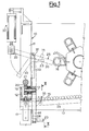
- an equipment for loading bars is structurally comprised of a supporting frame 10 including posts 11, longitudinal members 12 and cross-pieces 13.
- a plurality of rocking arms 14 which automatically draw the bars 15 out a supply and carry said bars in correspondence with a plurality of channel-shaped jaws 16 arranged in an indexing type configuration. Said jaws feed in a guided fashion each bar 15 to the machine tool, for example a lathe, using an arrangement known per se, and therefore not herein described.
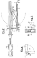
- each arm 14 is fastened to one end of a pin 17 rotatable on a bearing support 18 fixed to one of the longitudinal members 12.
- a sector gear 19 keyed to pin 17 at the end thereof opposite to arm 14 is meshing with a rack 20 fastened to a guided actuating stem 21 which is driven in a reciprocating movement by means of an actuator designated generally by the reference numeral 22, for example a bydraulic cylinder (Fig. 2.).
- stem 21 is single and is provided with a plurality of mutually spaced racks 20 corresponding exactly to the plurality of arms 14; it is thus formed a perfect actuating synchronism.
- a comb device 29 cooperates with said plurality of arms 14 by drawing out the bar 15 which has been lifted by arms 14 and letting said bar slide within the open jaw 16.
- said comb device 29 is comprised of a plurality of spaced prongs 30 fastened to a shaft 31 driven for rotation by means of an actuator 32 through a connecting rod 33.
- a plurality of bars ' 15 can, for example, be fed by gravity in correspondence to the lifting arms 14 by means of a sloping chute or platform provided by a plurality of U-shaped beams 34, preferably said platform having an adjustable slope so as to assure the bar feeding for any size of the bar cross-section.
- the arms 14 are then driven back to the lower starting position, and meanwhile a new bar 15 has arrived at rest freely against the retainer members 35. Said return movement of the arms 14 is permitted by the rocking movement of the corresponding dogs 23, in the position shown by dot-dash lines in Fig. 4, at the time of the collision with the bar 15 already in position ready for the next operative sequence.
Landscapes
- Engineering & Computer Science (AREA)
- Mechanical Engineering (AREA)
- Feeding Of Workpieces (AREA)
- Turning (AREA)
Applications Claiming Priority (2)
| Application Number | Priority Date | Filing Date | Title |
|---|---|---|---|
| ITMI1984U21909U IT8421909U1 (it) | 1984-05-24 | 1984-05-24 | Apparecchiatura per il caricamento di barre da lavorare ad un dispositivo per la presentazione e l'alimentazione di barre ad una macchina untensile. |
| IT2190984U | 1984-05-24 |
Publications (1)
| Publication Number | Publication Date |
|---|---|
| EP0166471A1 true EP0166471A1 (de) | 1986-01-02 |
Family
ID=11188608
Family Applications (1)
| Application Number | Title | Priority Date | Filing Date |
|---|---|---|---|
| EP85200724A Withdrawn EP0166471A1 (de) | 1984-05-24 | 1985-05-09 | Maschinelle Stangenhebe- und Zuführungseinrichtung zu einer Werkzeugmaschine |
Country Status (4)
| Country | Link |
|---|---|
| US (1) | US4639180A (de) |
| EP (1) | EP0166471A1 (de) |
| JP (1) | JPH0626762B2 (de) |
| IT (1) | IT8421909U1 (de) |
Cited By (1)
| Publication number | Priority date | Publication date | Assignee | Title |
|---|---|---|---|---|
| EP0311845A3 (de) * | 1987-10-14 | 1990-10-24 | I.E.M.C.A. S.p.a. Industria Elettromeccanica Complessi Automatici | Stangenladevorrichtung für eine Mehrspannfuttermaschine |
Families Citing this family (4)
| Publication number | Priority date | Publication date | Assignee | Title |
|---|---|---|---|---|
| JPH01237742A (ja) * | 1988-03-17 | 1989-09-22 | Mitsubishi Electric Corp | メモリ保護回路 |
| US6983837B1 (en) * | 2004-07-30 | 2006-01-10 | Chun-Liang Chen | Finished product receiving unit used in a corrugated metal sheet member making machine |
| US7097023B1 (en) * | 2004-07-30 | 2006-08-29 | Chun-Liang Chen | Finished product receiving unit of a corrugated metal sheet member making machine |
| MX350790B (es) * | 2012-01-20 | 2017-09-19 | A & R Carton Lund Ab | Aparato y método para colocar una pala en un contenedor. |
Citations (5)
| Publication number | Priority date | Publication date | Assignee | Title |
|---|---|---|---|---|
| DE1174594B (de) * | 1957-12-02 | 1964-07-23 | Ratby Engineering Company Ltd | Zufuehreinrichtung an stangenverarbeitenden Werkzeugmaschinen |
| CH553020A (de) * | 1972-06-20 | 1974-08-30 | Azuma Sangyo Co Ltd | Vorrichtung fuer die zufuhr von stangenmaterial in eine mehrspindlige automatische werkzeugmaschine. |
| DE2401064B2 (de) * | 1973-12-18 | 1976-02-19 | Eunipp Ag, Zug (Schweiz) | Selbsttaetig arbeitende werkstoffstangen-vorschubeinrichtung fuer mehrspindeldrehautomaten, insbesondere fuer mehrspindellangdrehautomaten |
| CH582033A5 (de) * | 1972-10-07 | 1976-11-30 | Iemca Spa Ind Elettromeccanica | |
| GB2033264A (en) * | 1978-10-05 | 1980-05-21 | Cucchi Pietro Sdf | Feeder apparatus in association with a multi-mandrel lathe and an automatic magazine for the feeder |
Family Cites Families (6)
| Publication number | Priority date | Publication date | Assignee | Title |
|---|---|---|---|---|
| US1766573A (en) * | 1926-06-22 | 1930-06-24 | Hartford Empire Co | Apparatus for handling glassware |
| US2835372A (en) * | 1953-08-20 | 1958-05-20 | Harry W Moore | Insulating machine |
| US2896796A (en) * | 1957-11-04 | 1959-07-28 | Blaw Knox Co | Pipe lowering device |
| US3062389A (en) * | 1960-06-15 | 1962-11-06 | Pettibone Mulliken Corp | Flask and mold handling mechanism |
| US3913751A (en) * | 1974-12-06 | 1975-10-21 | Robert Friedman | Apparatus for automatically feeding and removing cylindrical bodies to and from a working head |
| SU818813A1 (ru) * | 1978-06-26 | 1981-04-07 | Всесоюзный Научно-Исследовательскийинститут Технологии Насосногомашиностроения | Автомат дл обработки деталей |
-
1984
- 1984-05-24 IT ITMI1984U21909U patent/IT8421909U1/it unknown
-
1985
- 1985-05-09 EP EP85200724A patent/EP0166471A1/de not_active Withdrawn
- 1985-05-15 US US06/734,043 patent/US4639180A/en not_active Expired - Fee Related
- 1985-05-24 JP JP60110575A patent/JPH0626762B2/ja not_active Expired - Lifetime
Patent Citations (5)
| Publication number | Priority date | Publication date | Assignee | Title |
|---|---|---|---|---|
| DE1174594B (de) * | 1957-12-02 | 1964-07-23 | Ratby Engineering Company Ltd | Zufuehreinrichtung an stangenverarbeitenden Werkzeugmaschinen |
| CH553020A (de) * | 1972-06-20 | 1974-08-30 | Azuma Sangyo Co Ltd | Vorrichtung fuer die zufuhr von stangenmaterial in eine mehrspindlige automatische werkzeugmaschine. |
| CH582033A5 (de) * | 1972-10-07 | 1976-11-30 | Iemca Spa Ind Elettromeccanica | |
| DE2401064B2 (de) * | 1973-12-18 | 1976-02-19 | Eunipp Ag, Zug (Schweiz) | Selbsttaetig arbeitende werkstoffstangen-vorschubeinrichtung fuer mehrspindeldrehautomaten, insbesondere fuer mehrspindellangdrehautomaten |
| GB2033264A (en) * | 1978-10-05 | 1980-05-21 | Cucchi Pietro Sdf | Feeder apparatus in association with a multi-mandrel lathe and an automatic magazine for the feeder |
Cited By (1)
| Publication number | Priority date | Publication date | Assignee | Title |
|---|---|---|---|---|
| EP0311845A3 (de) * | 1987-10-14 | 1990-10-24 | I.E.M.C.A. S.p.a. Industria Elettromeccanica Complessi Automatici | Stangenladevorrichtung für eine Mehrspannfuttermaschine |
Also Published As
| Publication number | Publication date |
|---|---|
| IT8421909V0 (it) | 1984-05-24 |
| US4639180A (en) | 1987-01-27 |
| JPS6130304A (ja) | 1986-02-12 |
| JPH0626762B2 (ja) | 1994-04-13 |
| IT8421909U1 (it) | 1985-11-24 |
Similar Documents
| Publication | Publication Date | Title |
|---|---|---|
| US3414967A (en) | Tool changer | |
| EP0587248B1 (de) | Einrichtung zum Zuführen von Stangenmaterial in Werkzeugmaschine | |
| SU854270A3 (ru) | Устройство дл укладки цилиндричес-КиХ издЕлий | |
| US4809917A (en) | Automatic wire replacing system for use in an automatic wire coiling apparatus | |
| DE3627866C2 (de) | ||
| US4639180A (en) | Equipment for loading bars to be machined on a device for presenting and feeding said bars to a machine tool | |
| EP0356654A1 (de) | Einrichtung zum Zuführen von (Packungs-) Zuschnitten zu einer Verpackungsmaschine | |
| US4867297A (en) | Board exchanging apparatus | |
| US4817888A (en) | Multiple spindle winding machine for electric coils | |
| US4203514A (en) | Apparatus for feeding workpieces intermittently | |
| US4540084A (en) | Device for automatically transferring printed circuit base plates from the loading to the printing zone | |
| CN109514135B (zh) | 一种抽屉导轨的自动焊接机 | |
| DE69114817T2 (de) | Vorrichtung zum speichern und fördern von gestapelten teilen. | |
| DE3501113C2 (de) | ||
| EP0142850B1 (de) | Werkzeugmaschine mit zwei Werkzeugwechslern | |
| DE3508282A1 (de) | Einrichtung zum zufuehren von paletten mit werkstuecken zu einer rechnergesteuerten messmaschine | |
| DE2363030C3 (de) | Vorrichtung zum Beladen von Transportbehältern | |
| DE10021365C2 (de) | Bedienanordnung zum Bedienen eines Produktlagerregals, insbesondere einer Kommissioniervorrichtung | |
| SU1437184A1 (ru) | Загрузочное устройство | |
| EP0737542B1 (de) | Stangenzuführvorrichtung für Drehautomaten | |
| SU1524959A1 (ru) | Устройство дл отделени верхней заготовки от стопы и подачи ее в зону обработки | |
| KR910000571Y1 (ko) | 자동 공작기 | |
| SU984706A1 (ru) | Устройство дл сверлени отверстий | |
| DE2457866A1 (de) | Einrichtung zum selbsttaetigen wechseln von werkzeugen an werkzeugmaschinen | |
| SU1313643A1 (ru) | Загрузочно-разгрузочное устройство к металлорежущему станку |
Legal Events
| Date | Code | Title | Description |
|---|---|---|---|
| PUAI | Public reference made under article 153(3) epc to a published international application that has entered the european phase |
Free format text: ORIGINAL CODE: 0009012 |
|
| AK | Designated contracting states |
Designated state(s): AT BE CH DE FR GB IT LI LU NL SE |
|
| 17P | Request for examination filed |
Effective date: 19860613 |
|
| 17Q | First examination report despatched |
Effective date: 19870811 |
|
| STAA | Information on the status of an ep patent application or granted ep patent |
Free format text: STATUS: THE APPLICATION IS DEEMED TO BE WITHDRAWN |
|
| 18D | Application deemed to be withdrawn |
Effective date: 19880809 |
|
| RIN1 | Information on inventor provided before grant (corrected) |
Inventor name: CUCCHI, PIETRO Inventor name: CUCCHI, GIOVANNI |