EP0166689A1 - Matériel pour pistes d'accés aux chantiers de constructions ou pour pistes provisoires - Google Patents
Matériel pour pistes d'accés aux chantiers de constructions ou pour pistes provisoires Download PDFInfo
- Publication number
- EP0166689A1 EP0166689A1 EP85810265A EP85810265A EP0166689A1 EP 0166689 A1 EP0166689 A1 EP 0166689A1 EP 85810265 A EP85810265 A EP 85810265A EP 85810265 A EP85810265 A EP 85810265A EP 0166689 A1 EP0166689 A1 EP 0166689A1
- Authority
- EP
- European Patent Office
- Prior art keywords
- elements
- material according
- mats
- coupling
- flat
- Prior art date
- Legal status (The legal status is an assumption and is not a legal conclusion. Google has not performed a legal analysis and makes no representation as to the accuracy of the status listed.)
- Withdrawn
Links
Images


Classifications
-
- E—FIXED CONSTRUCTIONS
- E01—CONSTRUCTION OF ROADS, RAILWAYS, OR BRIDGES
- E01C—CONSTRUCTION OF, OR SURFACES FOR, ROADS, SPORTS GROUNDS, OR THE LIKE; MACHINES OR AUXILIARY TOOLS FOR CONSTRUCTION OR REPAIR
- E01C9/00—Special pavings; Pavings for special parts of roads or airfields
- E01C9/08—Temporary pavings
Definitions
- the present invention relates to material for a construction or emergency runway according to the preamble of claim 1.
- material for a construction or emergency runway is known from US Pat. No. 2,327,640, wherein the individual elements have the same cross-section over their entire length and consist of fabric-reinforced rubber.
- the individual mats have dimensions of around 2x15 m and are much too heavy and extensive for manual transport and laying in the intended version. Similar mats made from old vehicle tires are also known from DE-OS 27 19 442.
- the aim of the present invention is to provide material for a construction or emergency runway which can be easily transported and laid by hand in larger, mat-like sections, which is relatively light, and which nevertheless withstands the loads to be expected.
- This goal is achieved according to the characterizing part of claim 1.
- the flat elements and coupling elements are made of plastic or light metal, they have a relatively low weight.
- they are securely connected to one another and thus easily manipulate matable and transportable mat-like structures, the size of which can easily be adapted to the needs, that individual sections can be connected to any length of continuous runway, or by removing an excess section by pulling out a connecting element at a suitable point to achieve the desired total To achieve length of the slope.
- Individual mats are preferably connected by means of U-shaped clamps which can be plugged into the floor.
- the free spaces between the flat elements have the advantage that rainwater seeps away reliably, that on the other hand the ground can also dry under the slope and that the turf is at least partially protected. This also applies if a flow mat is laid under the slope.
- the flat elements are preferably centrally symmetrical, i.e. symmetrical with respect to three spatial center lines, so that no special attention has to be paid to how they are inserted into the mat.
- the elements then have the same unevenness on both sides, which ensures their grip for vehicles traveling over the slope. This grip can be increased by the way, and at the same time the flat elements can be stiffened by providing them with ribs or similar unevenness.
- the invention relates to an advantageous use of the slope, in appropriate dimensions, as a starting mat for motor vehicles.
- FIG. 1 The construction or emergency runway shown in FIG. 1 has flat elements 1 arranged like a checkerboard, which are connected to one another by means of coupling tubes or rods 2.
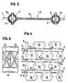
- FIG. 2 shows a longitudinal section through a flat element 1. It has a flat middle part 1a and a tubular eyelet 1b on opposite transverse sides.
- the coupling tubes 2 protrude through loops 1b, one behind the other, alternately in one or the other of two adjacent transverse rows of flat elements 1 of the mat, with little play, so that all flat elements 1 are loosely pivotably connected to one another, but in the longitudinal and transverse directions and transversely have little mutual play on the slope level.
- a securing element 3 is pushed onto adjacent coupling tubes 2 and connected by means of fastening elements projecting through aligned bores of these securing elements and the coupling tubes 2, for example screws 4 or split pins 5.
- the securing elements 3 have exactly the same cross section as the flat elements 1, but are considerably less wide.
- FIG. 2 shows the two possible fastening elements just mentioned, namely screws 4 or split pins 5, for example. However, other releasable fastening means can also be provided.
- the slope is held together in the transverse direction, and the coupling tubes 2 are secured against slipping out. So that the ends of the dome not fill pipes 2 with impurities, protective caps 6 are placed on the same.
- the flat elements 1 are preferably designed as plastic injection molded parts. Depending on the stress, a suitable plastic, preferably polyamide, and possibly also a reinforced plastic, can be used. Since the flat elements and securing elements have the same cross-section over their entire width, extruded profiles could also be cut to suitably dimensioned elements.
- the flat elements could also consist of light metal casting, in particular aluminum casting.
- the coupling tubes 2, or possibly full coupling rods, are preferably also made of plastic, but can optionally also consist of metal.
- the flat elements 1 made of plastic can, for example, have a length of approximately 20 cm, a width of approximately 10 cm and a thickness of 4 to 5 mm in the flat central part 1a.
- the eyelets 1b have a diameter of approximately 3 cm and approximately the same wall thickness as the central part 1a.
- a runway of this type, with plastic pipes 2 as coupling elements, is prefabricated, for example, in sections or mats of approximately 3.5 x 4 m and transported to the installation site. Such a section has a weight of around 80 kg and can therefore be easily laid by hand, for example by two men.
- the coupling of mats or sections of this type in the longitudinal direction takes place easily and quickly by pushing the free eyelets of the mat edges to be coupled into each other and covering them and coupling them by gradually inserting a coupling tube 2. This work, as well as the subsequent saving of the created connection, is easy to do by hand. The same applies to the possible shortening of a mat or a section by simply loosening the fastening element 4 or 5 and then removing it pull the coupling tube 2 to the desired location.
- mats with plastic elements of the type described above not only meet all requirements with regard to easy transport and laying even in hard-to-reach places, but also have the required strength and a certain roughness of the surface, which ensures sufficient adhesion for vehicles .
- the mats are preferably produced in widths which correspond exactly to the width of the construction runway, that is to say in widths of around 2 to 4 m.
- FIG. 3 shows an embodiment variant of the flat element, corresponding parts being identified in the same way as in FIGS. 1 and 2.
- the element differs from that according to FIG. 1 in that it is provided with stiffening ribs 7 and 8 on one or both sides.
- This element too is preferably centrally symmetrical, i.e. Equipped with ribs of the same type on both sides so that it can be used in any orientation.
- the ribs 7 and 8 not only serve to stiffen the element but also to grip the upper side of the element. This improves the grip of the driving wheels on the slopes. In general, however, the unevenness that is already caused by the eyelets 1b of the element according to FIG. 2 should suffice.
- Figures 1 and 2 show a flat element, which is characterized in its central symmetrical, rectangular shape by special simplicity, which also ensures efficient production. However, other shapes are also possible.
- the elements would not necessarily have to be of central symmetry, ie the flat middle part 1a could not lie in the plane of the axes of the eyelets 1b, for example.
- the middle section should also be not be rectangular.
- FIG. 4 shows that this central part can be hexagonal, for example, in order to enlarge the contact surface somewhat. In FIG. 4, too, corresponding parts are designated as in FIGS. 1-3.
- FIG. 5 and 6 show an embodiment variant in which elements 1 according to FIG. 1 are used. While it has previously been assumed that adjacent mats would be coupled in place during installation by means of conventional coupling rods 2, FIG. 5 shows adjoining ends of two mats, in which a coupling tube 2 is inserted into the outermost eyelets 1b of the elements 1, and the Distance between these outermost elements is determined by pipe sections 9. Locking washers 10 are welded to the ends of the coupling tubes. In this case, the ends of the mats placed against one another are coupled by means of U-shaped coupling and anchoring clips or brackets 11, the legs 11a of which are inserted into the ground. These brackets considerably simplify the coupling of adjacent mats, in the longitudinal and transverse directions.
- an appropriately designed mat can serve as a starting mat for motor vehicles.
Landscapes
- Engineering & Computer Science (AREA)
- Architecture (AREA)
- Civil Engineering (AREA)
- Structural Engineering (AREA)
- Road Paving Structures (AREA)
- Liquid Crystal (AREA)
- Road Signs Or Road Markings (AREA)
- Fittings On The Vehicle Exterior For Carrying Loads, And Devices For Holding Or Mounting Articles (AREA)
Applications Claiming Priority (2)
| Application Number | Priority Date | Filing Date | Title |
|---|---|---|---|
| CH2875/84 | 1984-06-14 | ||
| CH287584 | 1984-06-14 |
Publications (1)
| Publication Number | Publication Date |
|---|---|
| EP0166689A1 true EP0166689A1 (fr) | 1986-01-02 |
Family
ID=4243537
Family Applications (1)
| Application Number | Title | Priority Date | Filing Date |
|---|---|---|---|
| EP85810265A Withdrawn EP0166689A1 (fr) | 1984-06-14 | 1985-06-10 | Matériel pour pistes d'accés aux chantiers de constructions ou pour pistes provisoires |
Country Status (3)
| Country | Link |
|---|---|
| EP (1) | EP0166689A1 (fr) |
| FI (1) | FI852344A7 (fr) |
| NO (1) | NO852383L (fr) |
Cited By (3)
| Publication number | Priority date | Publication date | Assignee | Title |
|---|---|---|---|---|
| WO2002063101A1 (fr) * | 2001-02-09 | 2002-08-15 | Terje Olaussen | Procédé, système et plot de fixation plus particulièrement destinés aux travaux routiers et/ou à la consolidation des sols des zones de pâturage et analogues, et particulièrement des sols meubles |
| GB2513239A (en) * | 2013-03-04 | 2014-10-22 | Easy Trac Invest Ltd | Ground-engageable surface |
| CN110459055A (zh) * | 2019-08-14 | 2019-11-15 | 山东高速股份有限公司 | 运营道路中既有避险车道安全性检测方法 |
Citations (5)
| Publication number | Priority date | Publication date | Assignee | Title |
|---|---|---|---|---|
| US2327640A (en) * | 1941-05-29 | 1943-08-24 | Adolph R Hendry | Surfacing mat for landing fields |
| CH507416A (fr) * | 1969-05-13 | 1971-05-15 | Rador S A | Elément pour la constitution d'un chemin de roulement pour véhicule |
| DE2658901A1 (de) * | 1976-12-24 | 1978-06-29 | Maschf Augsburg Nuernberg Ag | Faltbarer bodenbelag, insbesondere fuer behelfsmaessige fahrbahnen |
| DE2719442A1 (de) * | 1977-04-30 | 1978-11-02 | Anton Schumann | Aus altreifengummi herstellbare matte |
| DE3219735A1 (de) * | 1982-05-26 | 1983-12-01 | Fried. Krupp Gmbh, 4300 Essen | Verkehrsweg fuer nicht festen untergrund |
-
1985
- 1985-06-10 EP EP85810265A patent/EP0166689A1/fr not_active Withdrawn
- 1985-06-12 FI FI852344A patent/FI852344A7/fi not_active Application Discontinuation
- 1985-06-13 NO NO852383A patent/NO852383L/no unknown
Patent Citations (5)
| Publication number | Priority date | Publication date | Assignee | Title |
|---|---|---|---|---|
| US2327640A (en) * | 1941-05-29 | 1943-08-24 | Adolph R Hendry | Surfacing mat for landing fields |
| CH507416A (fr) * | 1969-05-13 | 1971-05-15 | Rador S A | Elément pour la constitution d'un chemin de roulement pour véhicule |
| DE2658901A1 (de) * | 1976-12-24 | 1978-06-29 | Maschf Augsburg Nuernberg Ag | Faltbarer bodenbelag, insbesondere fuer behelfsmaessige fahrbahnen |
| DE2719442A1 (de) * | 1977-04-30 | 1978-11-02 | Anton Schumann | Aus altreifengummi herstellbare matte |
| DE3219735A1 (de) * | 1982-05-26 | 1983-12-01 | Fried. Krupp Gmbh, 4300 Essen | Verkehrsweg fuer nicht festen untergrund |
Cited By (3)
| Publication number | Priority date | Publication date | Assignee | Title |
|---|---|---|---|---|
| WO2002063101A1 (fr) * | 2001-02-09 | 2002-08-15 | Terje Olaussen | Procédé, système et plot de fixation plus particulièrement destinés aux travaux routiers et/ou à la consolidation des sols des zones de pâturage et analogues, et particulièrement des sols meubles |
| GB2513239A (en) * | 2013-03-04 | 2014-10-22 | Easy Trac Invest Ltd | Ground-engageable surface |
| CN110459055A (zh) * | 2019-08-14 | 2019-11-15 | 山东高速股份有限公司 | 运营道路中既有避险车道安全性检测方法 |
Also Published As
| Publication number | Publication date |
|---|---|
| FI852344A0 (fi) | 1985-06-12 |
| FI852344L (fi) | 1985-12-15 |
| NO852383L (no) | 1985-12-16 |
| FI852344A7 (fi) | 1985-12-15 |
Similar Documents
| Publication | Publication Date | Title |
|---|---|---|
| DE69816898T2 (de) | Bodenverankerung für ein Schutzplanken-Ende | |
| DE69612757T2 (de) | Bodenverfestigungsplatten und multiplatten, mit diesen ausgestattenen bodenbedeckungsanordnungen | |
| DE3820930A1 (de) | Fahrbahntrenneinrichtung | |
| DE3811862C2 (de) | Absperr- bzw. Verkehrsleiteinrichtung | |
| DE2833611A1 (de) | Abwehreinrichtung, insbesondere fuer strassen | |
| DE4126250C2 (de) | Aus Spurträgern bestehendes Brückensystem | |
| EP3428343B1 (fr) | Cache de vision destiné à la protection contre les accidents et pied pour ce cache de vision | |
| DE3733846C2 (fr) | ||
| DE102008006251B4 (de) | Verbindungselement für einen Bodenbelag | |
| DE2658901A1 (de) | Faltbarer bodenbelag, insbesondere fuer behelfsmaessige fahrbahnen | |
| DE4403438C2 (de) | Leitwand für Kraftfahrzeuge | |
| DE2636983A1 (de) | Fahrbahntafel | |
| DE19805273B4 (de) | Hochbahnsteig | |
| DE10108033C1 (de) | Vorrichtung und Verfahren zur Herstellung einer Baustraße | |
| DE2410331A1 (de) | Transportable baustellen- und bauwegebefestigung | |
| EP1950349B1 (fr) | Revêtement de sol | |
| EP0669424B1 (fr) | Elément d'espacement pour fixer des largeurs de joints | |
| CH308515A (de) | Betonstrasse. | |
| DE102024106382B4 (de) | Kunststoff-Mehrzwecksystem zur Bewässerung und dessen Verwendung | |
| DE102024118634A1 (de) | Kunststoffgitter-Mehrzweckmodul und dessen Verwendung | |
| DE9004587U1 (de) | Adapter für Absperreinrichtungen | |
| DE102006056182B4 (de) | Verkehrsleitwand | |
| DE8807985U1 (de) | Fahrbahntrenneinrichtung | |
| EP1249256A1 (fr) | Pont pour tuyau | |
| WO2012052012A2 (fr) | Assemblage d'éléments, structure porteuse, en particulier pont, et procédé d'assemblage d'éléments |
Legal Events
| Date | Code | Title | Description |
|---|---|---|---|
| PUAI | Public reference made under article 153(3) epc to a published international application that has entered the european phase |
Free format text: ORIGINAL CODE: 0009012 |
|
| AK | Designated contracting states |
Designated state(s): AT BE DE FR GB IT LU NL SE |
|
| 17P | Request for examination filed |
Effective date: 19860109 |
|
| 17Q | First examination report despatched |
Effective date: 19861110 |
|
| STAA | Information on the status of an ep patent application or granted ep patent |
Free format text: STATUS: THE APPLICATION IS DEEMED TO BE WITHDRAWN |
|
| 18D | Application deemed to be withdrawn |
Effective date: 19870320 |