EP0166823A2 - Dispositif de débrayage pour véhicule à motour - Google Patents
Dispositif de débrayage pour véhicule à motour Download PDFInfo
- Publication number
- EP0166823A2 EP0166823A2 EP84200958A EP84200958A EP0166823A2 EP 0166823 A2 EP0166823 A2 EP 0166823A2 EP 84200958 A EP84200958 A EP 84200958A EP 84200958 A EP84200958 A EP 84200958A EP 0166823 A2 EP0166823 A2 EP 0166823A2
- Authority
- EP
- European Patent Office
- Prior art keywords
- vacuum
- clutch
- spring
- cylinder
- disengaging means
- Prior art date
- Legal status (The legal status is an assumption and is not a legal conclusion. Google has not performed a legal analysis and makes no representation as to the accuracy of the status listed.)
- Withdrawn
Links
- 230000007935 neutral effect Effects 0.000 claims description 6
- 239000003570 air Substances 0.000 description 3
- 230000004075 alteration Effects 0.000 description 2
- 239000012080 ambient air Substances 0.000 description 1
- 230000001276 controlling effect Effects 0.000 description 1
- 238000010586 diagram Methods 0.000 description 1
- 230000000694 effects Effects 0.000 description 1
- 239000012528 membrane Substances 0.000 description 1
- 230000010355 oscillation Effects 0.000 description 1
- 230000001105 regulatory effect Effects 0.000 description 1
- 230000008719 thickening Effects 0.000 description 1
Images

Classifications
-
- B—PERFORMING OPERATIONS; TRANSPORTING
- B60—VEHICLES IN GENERAL
- B60W—CONJOINT CONTROL OF VEHICLE SUB-UNITS OF DIFFERENT TYPE OR DIFFERENT FUNCTION; CONTROL SYSTEMS SPECIALLY ADAPTED FOR HYBRID VEHICLES; ROAD VEHICLE DRIVE CONTROL SYSTEMS FOR PURPOSES NOT RELATED TO THE CONTROL OF A PARTICULAR SUB-UNIT
- B60W30/00—Purposes of road vehicle drive control systems not related to the control of a particular sub-unit, e.g. of systems using conjoint control of vehicle sub-units
- B60W30/18—Propelling the vehicle
-
- B—PERFORMING OPERATIONS; TRANSPORTING
- B60—VEHICLES IN GENERAL
- B60W—CONJOINT CONTROL OF VEHICLE SUB-UNITS OF DIFFERENT TYPE OR DIFFERENT FUNCTION; CONTROL SYSTEMS SPECIALLY ADAPTED FOR HYBRID VEHICLES; ROAD VEHICLE DRIVE CONTROL SYSTEMS FOR PURPOSES NOT RELATED TO THE CONTROL OF A PARTICULAR SUB-UNIT
- B60W10/00—Conjoint control of vehicle sub-units of different type or different function
- B60W10/02—Conjoint control of vehicle sub-units of different type or different function including control of driveline clutches
-
- B—PERFORMING OPERATIONS; TRANSPORTING
- B60—VEHICLES IN GENERAL
- B60W—CONJOINT CONTROL OF VEHICLE SUB-UNITS OF DIFFERENT TYPE OR DIFFERENT FUNCTION; CONTROL SYSTEMS SPECIALLY ADAPTED FOR HYBRID VEHICLES; ROAD VEHICLE DRIVE CONTROL SYSTEMS FOR PURPOSES NOT RELATED TO THE CONTROL OF A PARTICULAR SUB-UNIT
- B60W10/00—Conjoint control of vehicle sub-units of different type or different function
- B60W10/10—Conjoint control of vehicle sub-units of different type or different function including control of change-speed gearings
-
- F—MECHANICAL ENGINEERING; LIGHTING; HEATING; WEAPONS; BLASTING
- F16—ENGINEERING ELEMENTS AND UNITS; GENERAL MEASURES FOR PRODUCING AND MAINTAINING EFFECTIVE FUNCTIONING OF MACHINES OR INSTALLATIONS; THERMAL INSULATION IN GENERAL
- F16D—COUPLINGS FOR TRANSMITTING ROTATION; CLUTCHES; BRAKES
- F16D25/00—Fluid-actuated clutches
- F16D25/08—Fluid-actuated clutches with fluid-actuated member not rotating with a clutching member
- F16D25/088—Fluid-actuated clutches with fluid-actuated member not rotating with a clutching member the line of action of the fluid-actuated members being distinctly separate from the axis of rotation
-
- F—MECHANICAL ENGINEERING; LIGHTING; HEATING; WEAPONS; BLASTING
- F02—COMBUSTION ENGINES; HOT-GAS OR COMBUSTION-PRODUCT ENGINE PLANTS
- F02B—INTERNAL-COMBUSTION PISTON ENGINES; COMBUSTION ENGINES IN GENERAL
- F02B1/00—Engines characterised by fuel-air mixture compression
- F02B1/02—Engines characterised by fuel-air mixture compression with positive ignition
- F02B1/04—Engines characterised by fuel-air mixture compression with positive ignition with fuel-air mixture admission into cylinder
-
- F—MECHANICAL ENGINEERING; LIGHTING; HEATING; WEAPONS; BLASTING
- F02—COMBUSTION ENGINES; HOT-GAS OR COMBUSTION-PRODUCT ENGINE PLANTS
- F02B—INTERNAL-COMBUSTION PISTON ENGINES; COMBUSTION ENGINES IN GENERAL
- F02B3/00—Engines characterised by air compression and subsequent fuel addition
- F02B3/06—Engines characterised by air compression and subsequent fuel addition with compression ignition
Definitions
- the present invention relates to the disengaging means for a motor vehicle which comprises a foot-operated clutch and a manually operated gear box.
- the present invention tends to give a solution to this problem.
- a structure has been invented in which the clutch of a motor vehicle, with running engine, after the clutch pedal has been treaded and the gear box has been put into its neutral position, r ⁇ mains disengaged when the clutch pedal is released thereafter.
- the oscillations caused by the non-uniformity of the engine cannot be guided then to the driving line, so that the clattering and r ⁇ ttling noises, which are very inconvenient for the passengers, will no longer appear.
- the European patent application 81201404.1 describes a disengaging gear with the abovementioned aim for a hydraulically operated clutch.
- the vacuum control means may comprise:
- the driver is used, when he wants to start the vehicle again, to tread the clutch pedal against the said spring action.
- the vacuum control device is carried out in such a way that owing to the vacuum force and owing to an additional spring force the clutch pedal yet returns into its original position. These forces are almost equal to the force of the springs in the clutch.
- the vacuum control system is provided between the clutch and the clutch pedal.
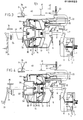
- the disengaging means belongs to a fly wheel 1 of the engine and a clutch housing 2 with therein the clutch comprising a clutch disc 3, a pressure group 4 and clutch springs 5.
- the pressure group 4 is connected by means of a lever 6 with a pull cable 7 which extends through the rope mantle 8 locked in between the fixed points 9 and 10.
- the vacuum control means comprises a housing 11 in which a cylinder 12 comprising a piston 13 is mounted. Between the cylinder 12 and The piston 13 a membrane 14 is provided. The piston 13 is formed such a way that it is capable of receiving a spring dish 15. A spiral spring 17 is mounted about the central box-like part 16 of the spring dish 15.
- the pull cable 7 is coupled to the cylinder 12 through an aperture in the housing 11 at 18.
- a tube 19 is provided which is inserted into the cylinder 12 through the apertures 20 and 21.
- the apertures 20 and 21 are provided in the control valve mousing 22 which is integrated with the cylinder 12.
- a control valve is mounted comprising a valve 23 and a valve spring 24.
- the valve 23 which is adapted to close the spertures 21 is slidably mounted onto the tube 19.
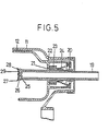
- the tube 19 is provided with radial apertures 25 at the end located in the vacuum room of cylinder 12. This is represented more clearly in figure 5. he tube 19 is closed at the end by a cover plate 26 onto which a closing plate 27 is mounted.
- the cover plate 26 comprises a protruding edge 28 and is provided with axial apertures.
- the housing 11 is integrated with a cylindrical box 30 provided with a stop edge 31. This stop edge 31 limits the stroke of the piston 13 when the latter is moved to the right in that then the flange 32 of the piston 13 contacts the edge 31.
- the clutch pedal is indicated by 33.
- Said pedal is coupled to the spring dish 15 through a pull cable 34 extending through the ropemantle 35, which is locked in between the fixed points 36 and 37.
- the pull cable 34 at its end is provided with a thickening 38 fixed in the spring dish 15.
- the gear lever is indicated by 39 and said lever may be in the neutral position N or in a switched position G.
- a rod 40 is mounted to the gear lever 39 and operates a switch 41 which is incorporated in an electric circuit.
- This circuit further comprises a solenoid 42 provided about the stem of a valve 43.
- the valve 43 is adapted to admit either the atmosphere into the tube 19 at A or vacuum of the engine or a pump at V.
- an air supply aperture is provided, indicated by 44.
- Figure 1 represents the normal driving situation.
- the clutch pedal 33 is in position D, i.e. that the clutch is not treaded.
- the gear lever 39 is in a switched position G.
- the vacuum room of the cylinder 12 is connected at A through tube 19 with the atmosphere through the apertures 25 which have not been closed by the valve 23, 24 since the clutch springs 5 keep the cylinder fully to the right by means of lever 6 and pull cable 7. If it is desired to stop the vehicle from this position, firstly the clutch 33 is treaded. The situation which is created then is indicated in figure 2.
- the pull cable 34 which is fixedly connected with the spring dish 15 with its thickened end 38, the spring dish 15, the piston 13, the cylinder 12 and the spring 17 are moved to the left.
- control valve housing 21 is moved to the left, and valve 23 is shifted to the left along tube 19.
- the radial apertures 25 are not yet closed now by the valve 23.
- the valve 43 cuts off the supply of atmosphere at A and opens the passage to engine vacuum or vacuum pump at V. Vacuum suction takes place now in the room between cylinder 12 and piston 13. The piston 13 is moved to the right whereby spring 17 is tensioned until the force in the spring 17 is equal to the force in the pull cable 7, which is drawn by the clutch springs 5. In case there is more vacuum suction when this stage is reached, cylinder 12 is moved slightly to the left under the influence of the vacuum force and at the same time piston 13 is moved to the right. Owing to the slight movement to the left of the cylinder 12 the radial apertures 25 are closed now by the valve 23. This is possible in that the aperture 21 is large enough to make the cover plate 26 pass through. The-movement to the right of piston 13 is effected by the force equilibrium between the spring force of spring 17 and the pull force in pull cable 7 and the vacuum force in the vacuum room.
- valve 23 is also moved to the right, whereby the radial apertures 25 are cleared. Then there is vacuum suction again in the vacuum room, whereby cylinder 12 is moved to the left and the apertures 25 are closed again. Owing to the action of valve 23 in this way the subatmospheric pressure in the vaccum room is regulated in such a way that the vacuum force remain in equilibrium with the force-in pull cable 7. After this stage the spring 17 is released whereby spring dish 15 is moved to the right and the clutch pedal comes into the position D.
- control mechanism 22, 23, 24, 25, 26, 17, 28 and 29 always effects an equilibrium between the vacuum force in cylinder 12 and the pull force in pull cable 7.
Landscapes
- Engineering & Computer Science (AREA)
- Mechanical Engineering (AREA)
- Transportation (AREA)
- Chemical & Material Sciences (AREA)
- Combustion & Propulsion (AREA)
- General Engineering & Computer Science (AREA)
- Automation & Control Theory (AREA)
- Hydraulic Clutches, Magnetic Clutches, Fluid Clutches, And Fluid Joints (AREA)
- Arrangement And Mounting Of Devices That Control Transmission Of Motive Force (AREA)
- Mechanical Operated Clutches (AREA)
- Control Of Vehicle Engines Or Engines For Specific Uses (AREA)
Priority Applications (2)
| Application Number | Priority Date | Filing Date | Title |
|---|---|---|---|
| EP84200958A EP0166823A3 (fr) | 1984-07-02 | 1984-07-02 | Dispositif de débrayage pour véhicule à motour |
| US06/627,074 US4603765A (en) | 1984-07-02 | 1984-07-02 | Means for maintaining clutch disengagement where transmission is neutral |
Applications Claiming Priority (2)
| Application Number | Priority Date | Filing Date | Title |
|---|---|---|---|
| EP84200958A EP0166823A3 (fr) | 1984-07-02 | 1984-07-02 | Dispositif de débrayage pour véhicule à motour |
| US06/627,074 US4603765A (en) | 1984-07-02 | 1984-07-02 | Means for maintaining clutch disengagement where transmission is neutral |
Publications (2)
| Publication Number | Publication Date |
|---|---|
| EP0166823A2 true EP0166823A2 (fr) | 1986-01-08 |
| EP0166823A3 EP0166823A3 (fr) | 1986-06-04 |
Family
ID=67482889
Family Applications (1)
| Application Number | Title | Priority Date | Filing Date |
|---|---|---|---|
| EP84200958A Withdrawn EP0166823A3 (fr) | 1984-07-02 | 1984-07-02 | Dispositif de débrayage pour véhicule à motour |
Country Status (2)
| Country | Link |
|---|---|
| US (1) | US4603765A (fr) |
| EP (1) | EP0166823A3 (fr) |
Cited By (4)
| Publication number | Priority date | Publication date | Assignee | Title |
|---|---|---|---|---|
| WO1989001881A1 (fr) * | 1987-08-22 | 1989-03-09 | Zahnradfabrik Friedrichshafen Ag | Systeme assiste d'embrayage et de changement de vitesse |
| WO1989001880A1 (fr) * | 1987-08-22 | 1989-03-09 | Zahnradfabrik Friedrichshafen Ag | Systeme assiste d'embrayage et de changement de vitesse |
| US5019524A (en) * | 1987-08-24 | 1991-05-28 | Hitachi, Ltd. | Method of manufacturing a heterojunction bipolar transistor |
| EP0458266A1 (fr) * | 1990-05-22 | 1991-11-27 | Csepel Autogyár | Dispositif de commande à air comprimé, notamment d'un embrayage à friction pour un moteur à combustion interne |
Families Citing this family (2)
| Publication number | Priority date | Publication date | Assignee | Title |
|---|---|---|---|---|
| JPS6387324A (ja) * | 1986-09-30 | 1988-04-18 | Aisin Seiki Co Ltd | 四輪駆動車の二輪・四輪切替制御装置 |
| FR2652548B1 (fr) * | 1989-09-29 | 1995-06-02 | Valeo | Timonerie de transmission de forces pour vehicules automobiles. |
Family Cites Families (9)
| Publication number | Priority date | Publication date | Assignee | Title |
|---|---|---|---|---|
| US2631700A (en) * | 1949-05-21 | 1953-03-17 | Bendix Aviat Corp | Clutch control mechanism |
| US3204730A (en) * | 1961-04-01 | 1965-09-07 | Magneti Marelli Spa | Automatic friction clutch control of motor vehicles |
| US3327817A (en) * | 1965-10-15 | 1967-06-27 | Ford Motor Co | Semiautomatic power transmission system for vehicle drivelines |
| US3841449A (en) * | 1972-08-29 | 1974-10-15 | Cybergenics Inc | Clutch with vacuum release motor |
| DE3010503A1 (de) * | 1980-03-19 | 1981-09-24 | Volkswagenwerk Ag, 3180 Wolfsburg | Einrichtung zur automatischen betaetigung einer kupplung eines fahrzeugs, insbesondere eines kraftfahrzeugs |
| EP0082893A1 (fr) * | 1981-12-29 | 1983-07-06 | Volvo Car B.V. | Dispositif de commande pour mécanisme de transmission |
| DE3229369A1 (de) * | 1982-08-06 | 1984-02-09 | Sachs Systemtechnik Gmbh | Reibungskupplung fuer brennkraftmaschinen-getriebene fahrzeuge |
| SE440055B (sv) * | 1983-03-30 | 1985-07-15 | Volvo Ab | Anordning for att vid tomgangskorning eliminera mekaniskt slammer i en till manuellt frikoppling ansluten, manuellt vexlad fordonsvexellada |
| NL8301888A (nl) * | 1983-05-27 | 1984-12-17 | Volvo Car Bv | Ontkoppelmechanisme voor een motorvoertuig. |
-
1984
- 1984-07-02 EP EP84200958A patent/EP0166823A3/fr not_active Withdrawn
- 1984-07-02 US US06/627,074 patent/US4603765A/en not_active Expired - Fee Related
Cited By (5)
| Publication number | Priority date | Publication date | Assignee | Title |
|---|---|---|---|---|
| WO1989001881A1 (fr) * | 1987-08-22 | 1989-03-09 | Zahnradfabrik Friedrichshafen Ag | Systeme assiste d'embrayage et de changement de vitesse |
| WO1989001880A1 (fr) * | 1987-08-22 | 1989-03-09 | Zahnradfabrik Friedrichshafen Ag | Systeme assiste d'embrayage et de changement de vitesse |
| US5056632A (en) * | 1987-08-22 | 1991-10-15 | Zahnradfabrik Friedrichshafen, Ag. | Auxiliary-power-activated clutch and gear-shifting device |
| US5019524A (en) * | 1987-08-24 | 1991-05-28 | Hitachi, Ltd. | Method of manufacturing a heterojunction bipolar transistor |
| EP0458266A1 (fr) * | 1990-05-22 | 1991-11-27 | Csepel Autogyár | Dispositif de commande à air comprimé, notamment d'un embrayage à friction pour un moteur à combustion interne |
Also Published As
| Publication number | Publication date |
|---|---|
| EP0166823A3 (fr) | 1986-06-04 |
| US4603765A (en) | 1986-08-05 |
Similar Documents
| Publication | Publication Date | Title |
|---|---|---|
| GB2057053A (en) | Motor vehicle speed control holding devices | |
| US3119477A (en) | Automatic parking brake release system | |
| GB476820A (en) | Improvements in and relating to variable speed transmission control mechanisms | |
| EP0166823A2 (fr) | Dispositif de débrayage pour véhicule à motour | |
| GB2067704A (en) | Automatic car-cooler clutch control apparatus | |
| US4366881A (en) | Flip-up control console | |
| US4533030A (en) | Clutch actuating system | |
| CA2008269A1 (fr) | Filtre a air robuste avec soupape a neige solidaire | |
| US2313232A (en) | Brake control mechanism | |
| US3698525A (en) | Clutch and throttle control | |
| US6006880A (en) | Power take-off release mechanism | |
| US4488410A (en) | Control apparatus for automotive air conditioner | |
| US1972446A (en) | Regulating device for an automatic automobile clutch | |
| EP0193502B1 (fr) | Dispositif de servo-embrayage à friction pour automatiser le fonctionnement de l'embrayage chez les véhicules à moteur de tout genre | |
| US3110355A (en) | Parking brake release | |
| JPS63284033A (ja) | 自動車のクラッチを自動操作する空気圧装置 | |
| US2551287A (en) | Vehicle control mechanism | |
| US2940561A (en) | Brake control system | |
| US3003823A (en) | Diesel engine vacuum pump | |
| GB1096469A (en) | Control mechanism for engine combined with infinitely variable gear | |
| US4144958A (en) | Device to effect control over the friction clutch of a transport vehicle | |
| US3398816A (en) | System for changing the fuel supply | |
| US2197480A (en) | Clutch control mechanism | |
| US2699686A (en) | Transmission operating mechanism | |
| US3051801A (en) | Combined switch and valve for parking brake release systems |
Legal Events
| Date | Code | Title | Description |
|---|---|---|---|
| PUAI | Public reference made under article 153(3) epc to a published international application that has entered the european phase |
Free format text: ORIGINAL CODE: 0009012 |
|
| AK | Designated contracting states |
Designated state(s): DE FR GB NL SE |
|
| PUAL | Search report despatched |
Free format text: ORIGINAL CODE: 0009013 |
|
| 17P | Request for examination filed |
Effective date: 19860320 |
|
| AK | Designated contracting states |
Kind code of ref document: A3 Designated state(s): DE FR GB NL SE |
|
| STAA | Information on the status of an ep patent application or granted ep patent |
Free format text: STATUS: THE APPLICATION IS DEEMED TO BE WITHDRAWN |
|
| 18D | Application deemed to be withdrawn |
Effective date: 19861205 |
|
| RIN1 | Information on inventor provided before grant (corrected) |
Inventor name: CRUIJSEN, HERMANUS GERARDUS MARIA |