EP0167077A2 - Elément pousseur - Google Patents
Elément pousseur Download PDFInfo
- Publication number
- EP0167077A2 EP0167077A2 EP85107772A EP85107772A EP0167077A2 EP 0167077 A2 EP0167077 A2 EP 0167077A2 EP 85107772 A EP85107772 A EP 85107772A EP 85107772 A EP85107772 A EP 85107772A EP 0167077 A2 EP0167077 A2 EP 0167077A2
- Authority
- EP
- European Patent Office
- Prior art keywords
- thrust unit
- vehicle
- unit according
- coupling
- tractor
- Prior art date
- Legal status (The legal status is an assumption and is not a legal conclusion. Google has not performed a legal analysis and makes no representation as to the accuracy of the status listed.)
- Granted
Links
Images


Classifications
-
- B—PERFORMING OPERATIONS; TRANSPORTING
- B62—LAND VEHICLES FOR TRAVELLING OTHERWISE THAN ON RAILS
- B62D—MOTOR VEHICLES; TRAILERS
- B62D55/00—Endless track vehicles
- B62D55/04—Endless track vehicles with tracks and alternative ground wheels, e.g. changeable from endless track vehicle into wheeled vehicle and vice versa
-
- B—PERFORMING OPERATIONS; TRANSPORTING
- B62—LAND VEHICLES FOR TRAVELLING OTHERWISE THAN ON RAILS
- B62D—MOTOR VEHICLES; TRAILERS
- B62D55/00—Endless track vehicles
- B62D55/06—Endless track vehicles with tracks without ground wheels
- B62D55/07—Mono-track vehicles
-
- A—HUMAN NECESSITIES
- A01—AGRICULTURE; FORESTRY; ANIMAL HUSBANDRY; HUNTING; TRAPPING; FISHING
- A01B—SOIL WORKING IN AGRICULTURE OR FORESTRY; PARTS, DETAILS, OR ACCESSORIES OF AGRICULTURAL MACHINES OR IMPLEMENTS, IN GENERAL
- A01B51/00—Undercarriages specially adapted for mounting on various kinds of agricultural tools or apparatus
- A01B51/02—Undercarriages specially adapted for mounting on various kinds of agricultural tools or apparatus propelled by a motor
-
- B—PERFORMING OPERATIONS; TRANSPORTING
- B62—LAND VEHICLES FOR TRAVELLING OTHERWISE THAN ON RAILS
- B62D—MOTOR VEHICLES; TRAILERS
- B62D49/00—Tractors
- B62D49/002—Tractors characterised by being of the low ground pressure type
-
- B—PERFORMING OPERATIONS; TRANSPORTING
- B62—LAND VEHICLES FOR TRAVELLING OTHERWISE THAN ON RAILS
- B62D—MOTOR VEHICLES; TRAILERS
- B62D49/00—Tractors
- B62D49/06—Tractors adapted for multi-purpose use
- B62D49/0621—Tractors adapted for multi-purpose use comprising traction increasing arrangements, e.g. all-wheel traction devices, multiple-axle traction arrangements, auxiliary traction increasing devices
- B62D49/0635—Tractors adapted for multi-purpose use comprising traction increasing arrangements, e.g. all-wheel traction devices, multiple-axle traction arrangements, auxiliary traction increasing devices using additional ground engaging means, e.g. endless tracks
-
- Y—GENERAL TAGGING OF NEW TECHNOLOGICAL DEVELOPMENTS; GENERAL TAGGING OF CROSS-SECTIONAL TECHNOLOGIES SPANNING OVER SEVERAL SECTIONS OF THE IPC; TECHNICAL SUBJECTS COVERED BY FORMER USPC CROSS-REFERENCE ART COLLECTIONS [XRACs] AND DIGESTS
- Y02—TECHNOLOGIES OR APPLICATIONS FOR MITIGATION OR ADAPTATION AGAINST CLIMATE CHANGE
- Y02A—TECHNOLOGIES FOR ADAPTATION TO CLIMATE CHANGE
- Y02A40/00—Adaptation technologies in agriculture, forestry, livestock or agroalimentary production
- Y02A40/10—Adaptation technologies in agriculture, forestry, livestock or agroalimentary production in agriculture
- Y02A40/28—Adaptation technologies in agriculture, forestry, livestock or agroalimentary production in agriculture specially adapted for farming
Definitions
- Swiss Patent No. 190 576 suggests making the wheels of a vehicle removable and replacing them with swing arms with caterpillar tracks.
- the specific soil pressure is reduced, but the tractive force is only slightly increased because its weight is too low.
- the object of the invention is to provide means which make it possible to increase the pulling force of a light tractor, an earth moving machine, a construction machine or an off-road vehicle without increasing the specific ground pressure.
- the invention solves this problem with a thrust unit, which has the specific features of claim 1.
- a tractor with a weight of 1700-2000 kg is the ideal vehicle for light work, such as hay harvesting, fertilizer spreading etc.
- the caterpillar-like thrust unit according to the invention can be coupled.
- This unit can be split into two or more guides with "rubber track” or “steel track” manufactured or. be used.
- This unit can have a dead weight of 500 kg to 2000 kg. Additional weights can be attached to the unit itself.
- the tractor with thrust unit leaves almost no traces even in the loosened field. Thanks to the large contact surface on which the tractor pushes off when pulling, there is practically no “slippage". Slip means “soil kneading", but it is also a loss of power and results in increased fuel consumption. This can be 40% and more.
- the thrust unit can be pulled up at the end of the field, for turning or on road trips. In certain cases, the thrust unit can be pushed and coupled between the tractor wheels from behind.
- the unit can be driven by means of a hydraulic motor integrated in the unit coupled with a reduction gear. It can be driven forward and backward.
- the drive can also be done mechanically via a (not shown) cardan shaft, through bevel gear and reduction or by electrical means. Because the point of application of the tractive force on the tractor is approx. 60 to 90 cm above the ground, a lever arm is created which relieves the front wheels and the rear wheels are additionally loaded; therefore all-wheel drive is practically worthless.
- the innovative thrust unit can absorb the increasing weight load that would otherwise fall on the rear wheels and, thanks to its large floor contact area and the fact that it is driven by motor power, provides the tractor with an extremely high pulling power without slippage at the lowest ground pressure.
- the thrust unit shown in Fig. 1 has a rubber crawler belt or a steel crawler belt 10, which extends approximately over the full width of the unit.
- the drive of the R aupenbandes is performed by a built-in hydraulic motor 11 which is driven from a tractor's hydraulic system through the hydraulic hoses 12 with connection couplings. 13
- a bracket 15 At the front of the frame 14 there is a bracket 15 which is guided over the crawler belt and has a pin 16 oriented horizontally in the direction of travel.
- the pin is used for coupling to a vehicle in order to increase its tractive force through the additional thrust.
- On the vehicle is a sleeve corresponding to the pin, as shown in Fig. 3.
- the bracket, the pin and the sleeve are dimensioned so strong that the tractor with its hydraulic drive can guide and lift the pushing device as required when turning.
- the thrust unit can also be driven mechanically from the tractor by means of a PTO shaft.
- An electric drive is also possible.
- the drive speed must be regulated so that the feed speed of the push device corresponds to the speed of the tractor or the vehicle to which it is coupled in order to increase the tractive force.
- the drive motor of the thrust unit should be able to be driven both forward and backward.
- FIG. 2 shows a tractor 20 with a thrust unit 22 coupled via a three-point suspension 21 Thrust unit is built so narrow that it can be attached between the rear wheels 23 of the tractor. Such an arrangement is particularly favorable since it allows the push device to take over part of the load of the drive wheels 23.
- the hydraulic lifting device 24 allows the thrust unit to be lifted when turning.
- FIG. 3 shows how a thrust unit 30, which is provided with a guide pin 31 as in FIG. 1, can be coupled to the gear block 32 of a tractor.
- the gear block is provided with a sleeve 33 into which the pin 31 is inserted.
- the thrust unit can pivot around the pin, which allows it to adapt to the terrain.
- the pin 31 is expediently designed to be liftable.
- the thrust unit 40 can be attached to the geared block 42 by means of a parallelogram linkage 41, as shown in FIG. 4.
- FIG. 5 shows a thrust unit 50, which is provided with a bridge 51, to which both the connecting elements 52 of a three-point hitch to the tractor (not shown) and a tillage implement 53 are coupled.
- the attachment of the processing device should be adjustable in height in order to be able to set the processing depth. If the thrust unit is raised by means of the tractor hydraulics, the processing device 53 is also raised at the same time.
- FIGS. 6 and 7 show the combination of a tractor 60, 70 with a coupled push device 61 and 71 and one Soil cultivation device 62, 72.
- the pushing device 61 is so narrow that it can be placed between the drive wheels 63 of the tractor.
- the pushing device 71 is wider, but shorter and must therefore be arranged behind the drive wheels 73 of the tractor.
- the thrust unit 61 has two parallel rubber band beads 64, which are provided with obliquely extending studs.
- the thrust unit 71 has four parallel steel crawler tracks 74 or rubber crawler belts.
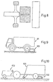
- FIG. 8 shows the size of the contact surfaces of the tractor wheels 63 and the pushing device 61 according to FIG. 6. It can be seen from this that the contact surface of the pushing device is much larger than that of the tractor wheels, so that the pushing device can exert large pushing forces without fear of slippage to have to.
- Fig. 9 shows another possible use of a thrust unit 90, in which the tensile and climbing ability of an all-terrain vehicle, e.g. of a military vehicle 91, increased. It is so narrow that it can be placed between the rear wheels.
- an all-terrain vehicle e.g. of a military vehicle 91
- the connection by means of a parallelogram according to FIG. 4 can advantageously be used.
- the push unit 100 can increase the pulling power of the relatively weak tractor if it has to pull the heavily loaded loading wagon uphill.
- the steerable vehicle can be used instead of the wheels e.g. when operating in the snow, be equipped with runners and operate in the same way as with the wheels.
Landscapes
- Engineering & Computer Science (AREA)
- Mechanical Engineering (AREA)
- Chemical & Material Sciences (AREA)
- Combustion & Propulsion (AREA)
- Transportation (AREA)
- Life Sciences & Earth Sciences (AREA)
- Soil Sciences (AREA)
- Environmental Sciences (AREA)
- Agricultural Machines (AREA)
- Devices For Conveying Motion By Means Of Endless Flexible Members (AREA)
- Iron Core Of Rotating Electric Machines (AREA)
- Surgical Instruments (AREA)
- Motor Power Transmission Devices (AREA)
Applications Claiming Priority (2)
| Application Number | Priority Date | Filing Date | Title |
|---|---|---|---|
| CH3243/84 | 1984-07-05 | ||
| CH3243/84A CH663936A5 (de) | 1984-07-05 | 1984-07-05 | Schubaggregat. |
Publications (3)
| Publication Number | Publication Date |
|---|---|
| EP0167077A2 true EP0167077A2 (fr) | 1986-01-08 |
| EP0167077A3 EP0167077A3 (en) | 1987-09-09 |
| EP0167077B1 EP0167077B1 (fr) | 1990-11-22 |
Family
ID=4251742
Family Applications (1)
| Application Number | Title | Priority Date | Filing Date |
|---|---|---|---|
| EP85107772A Expired - Lifetime EP0167077B1 (fr) | 1984-07-05 | 1985-06-22 | Elément pousseur |
Country Status (18)
| Country | Link |
|---|---|
| US (1) | US4657099A (fr) |
| EP (1) | EP0167077B1 (fr) |
| JP (1) | JPS6157473A (fr) |
| KR (1) | KR930000709B1 (fr) |
| AR (1) | AR242537A1 (fr) |
| AT (1) | ATE58510T1 (fr) |
| BR (1) | BR8503187A (fr) |
| CA (1) | CA1241682A (fr) |
| CH (1) | CH663936A5 (fr) |
| CS (1) | CS258471B2 (fr) |
| DD (1) | DD241718A5 (fr) |
| DE (1) | DE3580621D1 (fr) |
| ES (1) | ES8607147A1 (fr) |
| IL (1) | IL75658A0 (fr) |
| IN (1) | IN163528B (fr) |
| PL (1) | PL158964B1 (fr) |
| RO (1) | RO93180B (fr) |
| ZA (1) | ZA855085B (fr) |
Cited By (1)
| Publication number | Priority date | Publication date | Assignee | Title |
|---|---|---|---|---|
| EP0261279A1 (fr) * | 1986-09-22 | 1988-03-30 | Redexim B.V. | Appareil pour augmenter la surface de sustentation d'un véhicule à roues |
Families Citing this family (18)
| Publication number | Priority date | Publication date | Assignee | Title |
|---|---|---|---|---|
| EP0308404B2 (fr) * | 1987-04-10 | 1995-02-15 | DOMENIGHETTI, Domenico | Paveur-finisseur de routes avec une combinaison d'essieux a roues directrices et d'unites a chenilles |
| AT403708B (de) * | 1994-09-15 | 1998-05-25 | Plasser Bahnbaumasch Franz | Gleisbaumaschine |
| US6578926B2 (en) * | 2001-06-18 | 2003-06-17 | Eimco Llc | Mining machine having stabilizing apparatus and stabilizing apparatus |
| RU2222454C2 (ru) * | 2001-07-26 | 2004-01-27 | Южно-Российский государственный технический университет (Новочеркасский политехнический институт) | Трактор экологической версии |
| US7134829B2 (en) | 2004-03-09 | 2006-11-14 | Absolute Electronic Solutions, Inc. | Cargo trailer |
| US20060090910A1 (en) * | 2004-07-20 | 2006-05-04 | Shane Houck | Implement convertible between use configuration and transport configuration |
| US7950675B1 (en) | 2005-05-13 | 2011-05-31 | Absolute Electronic Solutions, Inc. | Cargo carrier |
| WO2009158329A2 (fr) * | 2008-06-27 | 2009-12-30 | Absolute Electronic Solutions, Inc. | Véhicule tracteur de semi-remorque à plateau réglable |
| DE102008059467A1 (de) * | 2008-11-28 | 2010-06-10 | Claas Selbstfahrende Erntemaschinen Gmbh | Landwirtschaftliche Zugmaschine |
| ES2361309B1 (es) * | 2009-06-23 | 2012-05-16 | Fcc Construccion S.A. | Procedimiento de instalación de v�?a férrea, sobre balasto, sin v�?a auxiliar. |
| US8931573B1 (en) * | 2012-08-03 | 2015-01-13 | Richard A. Gramlow | Toolbar implement |
| US20150274227A1 (en) * | 2014-03-26 | 2015-10-01 | Mubarak Aljahmi | Vehicle-mounted Traction Apparatus |
| US9781873B2 (en) | 2014-11-19 | 2017-10-10 | Cnh Industrial America Llc | Agricultural implement having power assist carrier wheels |
| SE539010C2 (sv) * | 2015-07-03 | 2017-03-21 | Komatsu Forest Ab | Anordning och fordon avsett för skogsbruk |
| SE539013C2 (sv) * | 2015-07-03 | 2017-03-21 | Komatsu Forest Ab | Anordning och fordon avsett för skogsbruk |
| SE539015C2 (sv) * | 2015-07-03 | 2017-03-21 | Komatsu Forest Ab | Anordning och fordon avsett för skogsbruk |
| WO2019079901A1 (fr) * | 2017-10-25 | 2019-05-02 | Camso Inc. | Dispositif de chenille pour le déplacement d'un véhicule |
| CN109811817B (zh) * | 2019-01-24 | 2021-07-06 | 上海大学 | 一种低扰动度的基坑平整机 |
Family Cites Families (12)
| Publication number | Priority date | Publication date | Assignee | Title |
|---|---|---|---|---|
| CH108013A (de) * | 1924-03-27 | 1925-05-16 | E Deloff | Landwirtschaftlicher Traktor. |
| US1729374A (en) * | 1926-08-31 | 1929-09-24 | Charles S Ehrhart | Endless-track attachment for trucks |
| US2714933A (en) * | 1953-06-05 | 1955-08-09 | Francis D Harris | Auxiliary endless-tread traction device for vehicles |
| US3526290A (en) * | 1968-04-23 | 1970-09-01 | Syer S Caudill | Traction device for vehicles |
| US3791052A (en) * | 1970-01-26 | 1974-02-12 | Lely Nv C Van Der | Tractor comprising a pivotable driver seat |
| DE2313161A1 (de) * | 1973-03-16 | 1974-09-19 | Karl Hoelle | Schlepper mit zusaetzlichen boden-antriebselementen |
| DK262176A (da) * | 1976-06-11 | 1977-12-12 | Rosenberg & Wiboltt Ro Wi | Redskabsopheng |
| JPS5320237A (en) * | 1976-08-08 | 1978-02-24 | Kouji Toyoura | Speciallpurpose vehicle with endless track |
| US4340127A (en) * | 1977-08-30 | 1982-07-20 | Broberg Peter O | Tractor |
| US4174757A (en) * | 1977-10-03 | 1979-11-20 | Caterpillar Tractor Co. | Material ripping vehicle |
| DE3302405A1 (de) * | 1983-01-25 | 1984-07-26 | Jeffery Morris Griffith New South Wales Pagett | Befoerderungseinrichtung |
| US4541498A (en) * | 1983-10-11 | 1985-09-17 | Pitchford A H | Apparatus for increasing vehicle mobility |
-
1984
- 1984-07-05 CH CH3243/84A patent/CH663936A5/de not_active IP Right Cessation
-
1985
- 1985-06-22 EP EP85107772A patent/EP0167077B1/fr not_active Expired - Lifetime
- 1985-06-22 DE DE8585107772T patent/DE3580621D1/de not_active Expired - Lifetime
- 1985-06-22 AT AT85107772T patent/ATE58510T1/de not_active IP Right Cessation
- 1985-06-27 IL IL75658A patent/IL75658A0/xx not_active IP Right Cessation
- 1985-06-28 ES ES544659A patent/ES8607147A1/es not_active Expired
- 1985-07-02 RO RO119381A patent/RO93180B/ro unknown
- 1985-07-03 BR BR8503187A patent/BR8503187A/pt not_active IP Right Cessation
- 1985-07-03 US US06/751,499 patent/US4657099A/en not_active Expired - Fee Related
- 1985-07-03 DD DD85278217A patent/DD241718A5/de not_active IP Right Cessation
- 1985-07-04 KR KR1019850004800A patent/KR930000709B1/ko not_active Expired - Fee Related
- 1985-07-04 PL PL1985254369A patent/PL158964B1/pl unknown
- 1985-07-04 AR AR85300912A patent/AR242537A1/es active
- 1985-07-04 CA CA000486310A patent/CA1241682A/fr not_active Expired
- 1985-07-05 CS CS855068A patent/CS258471B2/cs unknown
- 1985-07-05 JP JP60146893A patent/JPS6157473A/ja active Pending
- 1985-07-05 IN IN501/CAL/85A patent/IN163528B/en unknown
- 1985-07-05 ZA ZA855085A patent/ZA855085B/xx unknown
Cited By (1)
| Publication number | Priority date | Publication date | Assignee | Title |
|---|---|---|---|---|
| EP0261279A1 (fr) * | 1986-09-22 | 1988-03-30 | Redexim B.V. | Appareil pour augmenter la surface de sustentation d'un véhicule à roues |
Also Published As
| Publication number | Publication date |
|---|---|
| IL75658A0 (en) | 1985-10-31 |
| KR860000987A (ko) | 1986-02-22 |
| CS258471B2 (en) | 1988-08-16 |
| RO93180A (fr) | 1988-04-30 |
| ATE58510T1 (de) | 1990-12-15 |
| CS506885A2 (en) | 1988-01-15 |
| CA1241682A (fr) | 1988-09-06 |
| DE3580621D1 (de) | 1991-01-03 |
| US4657099A (en) | 1987-04-14 |
| PL254369A1 (en) | 1986-06-17 |
| EP0167077A3 (en) | 1987-09-09 |
| DD241718A5 (de) | 1986-12-24 |
| PL158964B1 (pl) | 1992-10-30 |
| ZA855085B (en) | 1986-02-26 |
| CH663936A5 (de) | 1988-01-29 |
| BR8503187A (pt) | 1986-03-25 |
| AR242537A1 (es) | 1993-04-30 |
| EP0167077B1 (fr) | 1990-11-22 |
| RO93180B (ro) | 1988-05-02 |
| IN163528B (fr) | 1988-10-08 |
| KR930000709B1 (ko) | 1993-01-30 |
| ES8607147A1 (es) | 1986-06-01 |
| ES544659A0 (es) | 1986-06-01 |
| JPS6157473A (ja) | 1986-03-24 |
Similar Documents
| Publication | Publication Date | Title |
|---|---|---|
| EP0167077B1 (fr) | Elément pousseur | |
| DE1966712A1 (de) | Geraetesatz | |
| DE6939004U (de) | Schlepper mit ladeflaeche. | |
| AT394833B (de) | Landwirtschaftlicher schlepper | |
| EP0297430B1 (fr) | Véhicule de traction ou de charge comprenant un espace libre entre les roues arrières | |
| DE859073C (de) | Schlepper, insbesondere fuer landwirtschaftliche Zwecke, mit veraenderlichem Radstand | |
| DE102009014874A1 (de) | Ein an das Kupplungselement eines Ackerschleppers ankuppelbares landwirtschaftliches Gerät | |
| DE1188448B (de) | Zweiachsiger Schlepper fuer landwirtschaftliche Zwecke | |
| DE19743039A1 (de) | Trägerfahrzeug | |
| DE202009015805U1 (de) | Fahrzeug mit einer Aufbauspritze zum Ausbringen von flüssigen Dünge- und Pflanzenschutzmitteln | |
| DE905433C (de) | Arbeitsfahrzeug, insbesondere Raupenfahrzeug, fuer land- und forstwirtschaftliche Zwecke | |
| DE1069416B (de) | Motorgeräteträger | |
| DE3644158A1 (de) | Einachsiges fahrzeug, insbesondere fuer die landwirtschaft, den garten- und landschaftsbau | |
| DE102016119768A1 (de) | Dolly Fahrwerk mit Gummikettenlaufwerk an einer Sämaschine | |
| DE1805459U (de) | Landwirtschaftliches fahrzeug. | |
| DE1217798B (de) | Geraetetraeger, insbesondere fuer landwirtschaftliche Zwecke | |
| DE19730825A1 (de) | Landwirtschaftliche Arbeitsmaschine | |
| DD139784A1 (de) | Zentrifugalduengerstreuer | |
| DE2263328A1 (de) | Schlepper mit zusaetzlichen bodenantriebselementen | |
| DE835261C (de) | Zweiachsiger Motorschlepper mit Anhaengevorrichtung | |
| AT267934B (de) | Selbstfahrendes landwirtschaftliches Gerät | |
| DE1457776C (de) | Zentrifugalstreuer zum Verteilen von Düngemitteln | |
| DE858359C (de) | Verbindung von Schleppern mit mehr als zwei Raedern mit einem mittels Handrad lenkbaren Fahrgestell | |
| DE3608335A1 (de) | Schlepper, insbesondere fuer die landwirtschaft | |
| AT258010B (de) | Wenderechen für Schlepper |
Legal Events
| Date | Code | Title | Description |
|---|---|---|---|
| PUAI | Public reference made under article 153(3) epc to a published international application that has entered the european phase |
Free format text: ORIGINAL CODE: 0009012 |
|
| AK | Designated contracting states |
Designated state(s): AT BE DE FR GB IT NL SE |
|
| PUAL | Search report despatched |
Free format text: ORIGINAL CODE: 0009013 |
|
| RHK1 | Main classification (correction) |
Ipc: B62D 49/06 |
|
| AK | Designated contracting states |
Kind code of ref document: A3 Designated state(s): AT BE DE FR GB IT NL SE |
|
| 17P | Request for examination filed |
Effective date: 19880308 |
|
| 17Q | First examination report despatched |
Effective date: 19880923 |
|
| GRAA | (expected) grant |
Free format text: ORIGINAL CODE: 0009210 |
|
| AK | Designated contracting states |
Kind code of ref document: B1 Designated state(s): AT BE DE FR GB IT NL SE |
|
| REF | Corresponds to: |
Ref document number: 58510 Country of ref document: AT Date of ref document: 19901215 Kind code of ref document: T |
|
| ITF | It: translation for a ep patent filed | ||
| ET | Fr: translation filed | ||
| REF | Corresponds to: |
Ref document number: 3580621 Country of ref document: DE Date of ref document: 19910103 |
|
| GBT | Gb: translation of ep patent filed (gb section 77(6)(a)/1977) | ||
| ITTA | It: last paid annual fee | ||
| PLBE | No opposition filed within time limit |
Free format text: ORIGINAL CODE: 0009261 |
|
| STAA | Information on the status of an ep patent application or granted ep patent |
Free format text: STATUS: NO OPPOSITION FILED WITHIN TIME LIMIT |
|
| 26N | No opposition filed | ||
| PGFP | Annual fee paid to national office [announced via postgrant information from national office to epo] |
Ref country code: GB Payment date: 19930611 Year of fee payment: 9 |
|
| PGFP | Annual fee paid to national office [announced via postgrant information from national office to epo] |
Ref country code: SE Payment date: 19930614 Year of fee payment: 9 Ref country code: AT Payment date: 19930614 Year of fee payment: 9 |
|
| PGFP | Annual fee paid to national office [announced via postgrant information from national office to epo] |
Ref country code: NL Payment date: 19930630 Year of fee payment: 9 |
|
| PGFP | Annual fee paid to national office [announced via postgrant information from national office to epo] |
Ref country code: BE Payment date: 19930803 Year of fee payment: 9 |
|
| PGFP | Annual fee paid to national office [announced via postgrant information from national office to epo] |
Ref country code: FR Payment date: 19940609 Year of fee payment: 10 |
|
| PG25 | Lapsed in a contracting state [announced via postgrant information from national office to epo] |
Ref country code: GB Effective date: 19940622 Ref country code: AT Effective date: 19940622 |
|
| PGFP | Annual fee paid to national office [announced via postgrant information from national office to epo] |
Ref country code: DE Payment date: 19940622 Year of fee payment: 10 |
|
| PG25 | Lapsed in a contracting state [announced via postgrant information from national office to epo] |
Ref country code: SE Effective date: 19940623 |
|
| PG25 | Lapsed in a contracting state [announced via postgrant information from national office to epo] |
Ref country code: BE Effective date: 19940630 |
|
| BERE | Be: lapsed |
Owner name: BALTENSPERGER EDUARD Effective date: 19940630 |
|
| PG25 | Lapsed in a contracting state [announced via postgrant information from national office to epo] |
Ref country code: NL Effective date: 19950101 |
|
| EUG | Se: european patent has lapsed |
Ref document number: 85107772.7 Effective date: 19950110 |
|
| GBPC | Gb: european patent ceased through non-payment of renewal fee |
Effective date: 19940622 |
|
| NLV4 | Nl: lapsed or anulled due to non-payment of the annual fee | ||
| EUG | Se: european patent has lapsed |
Ref document number: 85107772.7 |
|
| PG25 | Lapsed in a contracting state [announced via postgrant information from national office to epo] |
Ref country code: FR Effective date: 19960229 |
|
| PG25 | Lapsed in a contracting state [announced via postgrant information from national office to epo] |
Ref country code: DE Effective date: 19960301 |
|
| REG | Reference to a national code |
Ref country code: FR Ref legal event code: ST |