EP0167099A2 - Appareil sanitaire - Google Patents
Appareil sanitaire Download PDFInfo
- Publication number
- EP0167099A2 EP0167099A2 EP85107891A EP85107891A EP0167099A2 EP 0167099 A2 EP0167099 A2 EP 0167099A2 EP 85107891 A EP85107891 A EP 85107891A EP 85107891 A EP85107891 A EP 85107891A EP 0167099 A2 EP0167099 A2 EP 0167099A2
- Authority
- EP
- European Patent Office
- Prior art keywords
- setting control
- control means
- cleaning water
- cleaning apparatus
- human body
- Prior art date
- Legal status (The legal status is an assumption and is not a legal conclusion. Google has not performed a legal analysis and makes no representation as to the accuracy of the status listed.)
- Granted
Links
Images




Classifications
-
- E—FIXED CONSTRUCTIONS
- E03—WATER SUPPLY; SEWERAGE
- E03D—WATER-CLOSETS OR URINALS WITH FLUSHING DEVICES; FLUSHING VALVES THEREFOR
- E03D9/00—Sanitary or other accessories for lavatories ; Devices for cleaning or disinfecting the toilet room or the toilet bowl; Devices for eliminating smells
- E03D9/08—Devices in the bowl producing upwardly-directed sprays; Modifications of the bowl for use with such devices ; Bidets; Combinations of bowls with urinals or bidets; Hot-air or other devices mounted in or on the bowl, urinal or bidet for cleaning or disinfecting
Definitions
- the present invention relates to a sanitary cleaning apparatus for cleaning the private parts of a human body seated on a close stool with warm water.
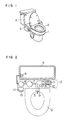
- Fig. 1 is a perspective view of a sanitary cleaning apparatus installed, in which reference numeral 2 designates a seat mounted on a close stool 1, numeral 3 a sanitary cleaning apparatus proper, and numeral 4 a cistern for storing water for washing the interior of the stool 1.
- Fig. 2 shows a configuration of a conventional sanitary cleaning apparatus, in which numeral 5 designates a nozzle for discharging the cleaning water against the parts to be cleaned of the human body seated on the seat 2, numeral 6 a water filter submerged in the water in the cistern 4, numeral 7 a water heater for storing and heating the cleaning water to proper temperature, and numeral 8 a pump for absorbing water from the cistern 4 through the water filter 6 and supplying it into the water heater under pressure while at the same time discharging the cleaning water derived from the warm water in the water heater 7 to the nozzle 5 under pressure, by being driven by a motor built therein.
- numeral 5 designates a nozzle for discharging the cleaning water against the parts to be cleaned of the human body seated on the seat 2
- numeral 6 a water filter submerged in the water in the cistern 4
- numeral 7 a water heater for storing and heating the cleaning water to proper temperature
- numeral 8 a pump for absorbing water from the c
- Numeral 9 designates a warm air outlet for blowing out the warm air for drying the object parts wetted with the cleaning water
- numeral 10 a wind tunnel
- numeral 11 a fan for supplying air to the warm air outlet 9 through the wind tunnel
- numeral 12 a motor for driving the fan
- numeral 13 a heater for heating the air supplied from the fan to proper temperature
- numeral 14 a control section for controlling the water heater 7, pump 8, motor 12 and heater 13, and numeral 15 an operating section for the control section 14.
- Fig. 3 is a front outside view of the operating section of a conventional apparatus, in which numeral 16 designates a cleaning adjusting knob including a variable resistor for turning on and off the cleaning water discharge means and setting the amount of discharge therefrom, and numeral 17 a drying temperature knob for turning on and off the drying means and switching the drying temperature.
- numeral 16 designates a cleaning adjusting knob including a variable resistor for turning on and off the cleaning water discharge means and setting the amount of discharge therefrom
- numeral 17 a drying temperature knob for turning on and off the drying means and switching the drying temperature.
- the cleaning adjusting knob 16 is fixed, and therefore upon operation of the operating switch 18 by a second user, the cleaning water of an amount set by a first user is discharged from the nozzle 5 and applied to the parts of his body uncomfortably.
- the present invention is intended to obviate these problems of the conventional apparatus, and the object thereof is to provide a sanitary cleaning apparatus comprising cleaning water discharge means for cleaning the parts to be washed of a human body seated on the stool seat with warm water and drying means for drying the parts wet with the cleaning water with warm air which is improved in operating efficiency and is usable comfortably.
- a sanitary cleaning apparatus comprising means for discharging cleaning water, functional means having a function identical to or different from the cleaning water discharge means, means for turning on and off the cleaning water discharge means and the functional means, first setting control means for setting selected one of the amount of actuation of the cleaning water discharge means and the functional means, second setting control means for changing the amount set by the first setting control means, and human body detector means for detecting the presence or absence of a human body, wherein the actuation amount of the means set by the first setting control means is set to the value of the first setting control means by the on-off operation of the on-off means, and is variable from the set value of the first setting control means by the operation of the second setting control means, the set value being returned to the value of the first setting control means by an absence detection signal of the human body detector means.
- the user when the user is desirous of cleaning his private parts, he may turn on and off the cleaning water discharge means by on-off means, so that the object parts of the user may be cleaned with the cleaning water in an amount of actuation of the cleaning water discharge means set by the first setting control means for setting the amount of actuation of the cleaning water discharge means.
- the second setting control means may be used.
- the temperature of the drying means set by the first setting control means is obtained by turning on and off the means for turning on and off the drying means, and subsequent change of temperature, if desired, may be effected by the second setting control means.
- the human body detector means detects it and clears the setting change by the second setting control means, thereby restoring the setting of the actuation amount to the value of the first setting control means.
- the very simple operation of the on-off means for the cleaning water discharge means and the drying means makes possible comfortable use of the stool in all cases. If it is desired to change the actuation amount of the cleaning water discharge means or the drying means depending on the physical condition or taste of the user, the second setting control means is used. Further, only when the user leaves the seat, the setting change by the second setting control means is cancelled, thereby automatically restoring the set value of the first setting control means. This achieves a high operating efficiency and eliminates the discomfort which might be caused by the failure to restore the set value.
- Fig. 5 is a partial appearance of a sanitary cleaning apparatus comprising first setting control means and second setting control means according to a first embodiment of the present invention.
- the first setting control means which is not required in the ordinary course of usage, is contained in a body 3 covered by a lid 19.
- Numeral 20 designates second setting control means.
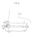
- Fig. 6 is a partially cut-away sectional view of a sanitary cleaning apparatus comprising human body detector means according to an embodiment of the present invention.
- Figs. 7 to 8 are enlarged partial views of the part A in Fig. 6.
- Numeral 22 designates a switch
- numeral 23 a lever for imparting the vertical motion of a rod 24 to the switch 22
- numeral 25 a spring, these four parts making up the human body detector means.
- Numerals 26 and 27 designate pieces of foot rubber for absorbing the shock between the seat 2 and the stool 1 at the time of opening or closing the seat 2, which foot rubber are kept distant from the stool 1 when the human body 21 is not seated on the seat 2. Under this condition, the spring 25 is expanded as shown in Fig. 7.
- human body detector means may be provided by a device for detecting the entry of a human body into the toilet.
- Fig. 9 is a front view of the first setting control means according to an embodiment of the present invention, in which numeral 28 designates a panel, numeral 29 a cleaning adjusting knob and numeral 30 a drying temperature control knob.
- Fig. 10 is a front view of the means 18 for turning on and off the drying means and the second setting control means 20 according to an embodiment of the present invention arranged on the surface of the body 3.
- Numeral 31 designates an on-switch of the means for turning on and off the drying means
- numeral 33 an off-switch of the means for turning on and off the cleaning water discharge means and the drying means.
- Each of the switches 32 and 33 includes a key switch operable by soft touch.
- Numeral 34 designates an adjusting operation knob the indication of which is represented by the second setting control means 18 for changing the setting of the warm air temperature of the drying means or the actuation amount for discharge from the cleaning water discharge means after the turning on of the on-switch 31 of the means for turning on and off the cleaning water discharge means or the on-switch 32 of the means for turning on and off the drying means.
- the knob 34 is turned clockwise, the actuation amount is increased, that is the amount of cleaning water actuation and the temperature of the warm air are increased.
- the knob 34 is turned counterclockwise, on the other hand, the actuation amount is decreased.
- the adjusting operation knob 34 is constructed in endless form.
- Fig 11 is a control block diagram of a sanitary cleaning apparatus according to an embodiment of the present invention.
- Numeral 35 designates second setting control means 18, including a pulse switch 35a operable clockwise and a pulse switch 35b operable counterclockwise, both interlocked with the adjusting operation knob 34.
- Numeral 36 designates an up-down counter for counting the pulses produced from the pulse switches 35, that is, for counting up the pulse switch 35a and counting down the switch 35b.
- Numeral 37 designates a tri-state buffer, and numeral 38 a latch circuit supplied with the switching operation of the on-switch 31 of the means for turning on and off the cleaning water discharge means, the on-switch 32 of the means for turning on and off the drying means, and the off-switch 33 of the means for turning off the cleaning water discharge means and the drying means.
- Numeral 38a designates an output terminal for turning on the analog switches 39 and 40 by the operation of the on-switch of the cleaning water discharge means
- numeral 38b an output terminal connected to a motor drive section 43 for turning on the analog switches 41 and 42 by the operation of the on-switch of the drying means and for supplying power to the motor 12 for driving a blow fan 11
- numeral 38c an output terminal for resetting the count of the counter 36 through a delay circuit 44 a predetermined time after opertion of the off-switch 33, the on-switch 31 of the means for turning on and off the cleaning water discharge means, and the on-switch 32 of the means for turning on and off the drying means.
- Numeral 45 designates an AND element for producing a logic product of the signal from the output terminal 38c and the signal produced from the output terminal 38a of the latch circuit 38 applied through the delay line 64 and a signal-inverting inverter 65.
- the value of the up-down counter 36 is transferred to a register 46.
- the value of the up-down counter 36 is transferred to a register 49 when the output of the AND element 47 is applied to the tri-state buffer 48.
- Numeral 66 designates an inverter, and numeral 67 a delay line. The value in the registers 46 and 4 9 is reset when the switch 22 of the human body detector section is turned off.
- Numeral 50 designates a select switch for selecting the register 46 or 49, which select switch applies the value of the register 49 to the adder 51 when a signal for turning on the analog switch 39 is applied thereto from the output terminal 38 a of the latch circuit 38.
- the signal for turning on the analog switch 41 is applied thereto from the output terminal 38b of the latch circuit 38, on the other hand, the value of the register 46 is applied to the adder 51.
- the output signals of this select switch 50 and the up-down counter 36 are added at the adder 51.
- Numeral 52 designates a variable resistor making up the first setting control means for setting the amount of actuation for discharge from the cleaning water discharge means
- numeral 53 a variable resistor making up the first setting control means for the temperature of the warm air of the drying means.
- the output voltage of the variable resistor 52 or 53 is selected by the analog switches 40 and 42, and A/D con- ver t ed by an A/D converter 54 for converting an analog value into a binary output, so that the output signal of the A/ D converter 54 is added to that of the adder 51 at another adder 55.
- the binary output of this adder 55 is converted into an analog value by a D/A converter 56.
- the output voltage of the D/A converter 56 is applied to a phase control section 58 of a bidirectional thyristor 57 for driving the cleaning pump 8 making up the cleaning water discharge means and a phase control section 60 of a bidirectional thyristor 59 for driving the heater 13 by the analog switches 39 and 41.
- Numeral 61 designates a resistor, 62 a DC power supply and 63 a commercial power supply.
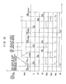
- Fig. 12 is a diagram showing waveforms of output voltages produced from the output terminal 6a of the D/A converter 56 and the switch 22 of the human body detector means and those produced by the operation of the on-switch 31 of the means for turning on and off the cleaning water discharge means, the on-switch 32 of the means for turning on and off the drying means, and the off-switch 33 of the means for turning off the cleaning water discharge means or the drying means.
- the switch 22 is turned on. If the off-switch 31 for the means for turning on and off the cleaning water discharge means is turned on under this condition, the outut 38a of the latch circuit 38 is produced to latch the circuit on the one hand and a reset pulse is produced from the terminal 38c on the other hand.
- the output voltage 56a of the D/A converter 56 is associated with the amount of actuation for discharge from the cleaning water discharge means by the output voltage of the variable resistor 52 discharge means by the output voltage of the variable resistor 52 representing the set value of the first setting control means of the cleaning water discharge means, so that when the pulse switch 35 is turned clockwise, the switch 35a is energized to increase the amount of actuation for discharge from the cleaning water discharge means.
- the output 38b of the latch circuit 36 is produced for latching the circuit, while at the same time producing a reset pulse from the terminal 38c, which is applied through the delay line 44 to reduce the count of the up-down counter 36 a predetermined time later.
- the count of the up-down counter 36 immediately before the zero resetting is such that since the "High” or “Low” state of the terminal 38b is delayed by the delay line 67, the output of the inverter 66 is kept “High” for a certain period of time after the on-off means 32 of the drying means.
- This output is applied to the AND circuit 47 for producing a logic product of the same output and reset pulse from the terminal 38c, and the resulting signal is applied to the register 49 through the tri-state buffer 48 controlled by the output signal of the AND circuit 47.
- the output voltage 56a of the D/A converter 56 is started at the warm air temperature of the drying means by the output voltage of the variable resistor 53 making up the set value of the first setting control means of the drying means, so that when the pulse switch 36 is turned clockwise, the switch 35b is actuated to reduce the output voltage, thus reducing the warm air temperature.
- a reset pulse is applied from the terminal 38c of the latch circuit 38 through the delay line 44 to the up-down counter 36. A predetermined time later, the count of the up-down counter 36 is reduced to zero.
- the count of the up-down counter 36 immediately before being reset to zero is such that since the terminal 38a is "Low", the output of the inverter 65 is kept “High” for a predetermined period of time after the off-switch 33 is turned on, so that the output is applied to the AND circuit 45 for producing a logic product of the same output and the reset pulse from the terminal 38c.
- the output of the AND circuit 45 is applied to the register 46 through the tri-state buffer 37 controlled by the output signal of the AND circuit 45.
- the switch 22 When the seat 2 is left after use, the switch 22 is turned on and the registers 49 and 46 are reset to zero. As a result, the initial setting for operation of the on-off means of the cleaning water discharge means and the drying means following the next seating of a human body is the same value as set by the first setting control means.
- the amount of actuation of the cleaning water of the cleaning water discharge means or the temperature of the warm air from the drying means may be set freely by the variable resistors 52, 53. Further, as long as the human body detector means is not turned off when the cleaning water detector means is on, assume that the second setting control means is started to start the setting, followed by the operation of the on-off means of the drying means and the turning-on of the cleaning water discharge means again. Then the amount of actuation equivalent to the set value used on the previous occasion is realized. In the case where the apparatus is used while the human body detector means is turned on, therefore, it is not necessary to operate the second setting control means.
- a sanitary cleaning apparatus comprising means for discharging the cleaning water, functional means having a function identical to or different from the cleaning water discharge means, means for turning on and off the cleaning water discharge means and the functional means, first setting control means provided separately from the on-off means for setting at least one of the amount of actuation of the cleaning water discharge means and the functional means, second setting control means for changing the set value of the first setting control means, and human body detector means for detecting the presence or absence of a human body, wherein the value of the means with the actuation amount thereof set by the first setting control means is set to the value set at the first setting control means, by the turning-on of the on-off means, which value is variable by the operation of the second setting control means and returned to the setting of the first setting control means by the human body detection signal of the human body detector means.
- the object parts of the user are cleaned with the amount of actuation for discharge from the cleaning water discharge means set by the first setting control means. If the amount of actuation for discharge from the cleaning water discharge means is to be changed subsequently, that is, if the amount of actuation of the cleaning water is to be increased or decreased, the second setting control means is used. If the user is to dry the object parts with the drying means making up the functional means employed in the apparatus, the temperature of the value set by the first setting control means is obtained for drying by turning on the on-off means of the drying means. If the temperature is to be changed further subsequently, the second setting control means is used. When the user leaves the seat upon termination of use of the stool, it is detected by the human body detector means and the setting change by the second setting control means is reset, so that the set amount of actuation is returned to the setting of the first setting control means.
- the second setting control means handles the work. Further, only when the user leaves the seat, the setting change by the second setting control means is reset to automatically return the setting to that of the first setting control means, thereby leading to a high operating efficiency and elimination of discomfort which might otherwise be caused by the failure to restore the set value.
Landscapes
- Health & Medical Sciences (AREA)
- Public Health (AREA)
- Molecular Biology (AREA)
- Epidemiology (AREA)
- Life Sciences & Earth Sciences (AREA)
- Engineering & Computer Science (AREA)
- Hydrology & Water Resources (AREA)
- Water Supply & Treatment (AREA)
- Bidet-Like Cleaning Device And Other Flush Toilet Accessories (AREA)
Applications Claiming Priority (2)
| Application Number | Priority Date | Filing Date | Title |
|---|---|---|---|
| JP59135640A JPS6114333A (ja) | 1984-06-29 | 1984-06-29 | 衛生洗浄装置 |
| JP135640/84 | 1984-06-29 |
Publications (3)
| Publication Number | Publication Date |
|---|---|
| EP0167099A2 true EP0167099A2 (fr) | 1986-01-08 |
| EP0167099A3 EP0167099A3 (en) | 1986-11-12 |
| EP0167099B1 EP0167099B1 (fr) | 1990-04-11 |
Family
ID=15156531
Family Applications (1)
| Application Number | Title | Priority Date | Filing Date |
|---|---|---|---|
| EP85107891A Expired EP0167099B1 (fr) | 1984-06-29 | 1985-06-26 | Appareil sanitaire |
Country Status (5)
| Country | Link |
|---|---|
| US (1) | US4598431A (fr) |
| EP (1) | EP0167099B1 (fr) |
| JP (1) | JPS6114333A (fr) |
| CA (1) | CA1235858A (fr) |
| DE (1) | DE3577114D1 (fr) |
Cited By (4)
| Publication number | Priority date | Publication date | Assignee | Title |
|---|---|---|---|---|
| EP0167098A3 (en) * | 1984-06-29 | 1986-08-20 | Matsushita Electric Industrial Co., Ltd. | Sanitary cleaning apparatus |
| DE3728658A1 (de) * | 1986-08-29 | 1988-04-07 | Aisin Seiki | Sanitaervorrichtung |
| US4875243A (en) * | 1986-06-16 | 1989-10-24 | Wileman Industries, Inc. | Toilet apparatus with automatic self-cleaning means |
| EP0475232A1 (fr) * | 1990-09-11 | 1992-03-18 | Matsushita Electric Industrial Co., Ltd. | Dispositif de lavage commandé |
Families Citing this family (15)
| Publication number | Priority date | Publication date | Assignee | Title |
|---|---|---|---|---|
| JPS6272834A (ja) * | 1985-09-24 | 1987-04-03 | アイシン精機株式会社 | 局部洗浄装置 |
| US4903347A (en) * | 1987-05-20 | 1990-02-27 | Garcia Gilbert C | Automated cleansing apparatus adaptable to a commode |
| JP2526320Y2 (ja) * | 1991-01-29 | 1997-02-19 | 矢崎総業株式会社 | 積載物計量装置 |
| USD355246S (en) | 1992-05-01 | 1995-02-07 | Toto Ltd. | Combined bidet, bidet control, toilet seat and cover |
| DE4407066C2 (de) * | 1993-03-04 | 1999-03-11 | Yazaki Corp | Dehnungssensor für eine Fahrzeuglastmeßvorrichtung |
| US5566402A (en) * | 1995-03-14 | 1996-10-22 | Rim Innovation And Marketing Consultants Inc. | Bidet apparatus for toilets |
| JP4054399B2 (ja) * | 1997-03-24 | 2008-02-27 | キヤノン株式会社 | 情報処理装置及びその方法 |
| RU2199630C2 (ru) | 2001-05-11 | 2003-02-27 | Титов Александр Михайлович | Биде-приставка к унитазу |
| USD496990S1 (en) | 2002-11-19 | 2004-10-05 | Aisin Seiki Kabushiki Kaisha | Bidet toilet seat unit |
| USD495794S1 (en) | 2002-11-19 | 2004-09-07 | Aisin Seiki Kabushiki Kaisha | Bidet toilet seat unit |
| USD492398S1 (en) | 2002-12-17 | 2004-06-29 | Aisin Seiki Kabushiki Kaisha | Toilet seat unit |
| USD500845S1 (en) * | 2003-06-12 | 2005-01-11 | Aisin Seiki Kabushiki Kaisha | Bidet toilet seat unit |
| JP2006090072A (ja) * | 2004-09-27 | 2006-04-06 | Aisin Seiki Co Ltd | 人体局部洗浄装置 |
| US9828755B1 (en) * | 2014-06-24 | 2017-11-28 | sigmund lindsay clements | Touch free automatic bidet |
| CN105425865B (zh) * | 2015-11-03 | 2017-10-27 | 上海科勒电子科技有限公司 | 防温度过冲的控制方法及控制系统 |
Family Cites Families (9)
| Publication number | Priority date | Publication date | Assignee | Title |
|---|---|---|---|---|
| US2875450A (en) * | 1956-08-17 | 1959-03-03 | Harry M Umann | Sanitary fixture |
| US3662407A (en) * | 1970-05-25 | 1972-05-16 | Donald E Colucci | Personal hygiene device |
| DE2751701A1 (de) * | 1977-11-19 | 1979-05-23 | Schieferstein Monika | Bidet-ansatz |
| FR2460661A2 (fr) * | 1978-07-26 | 1981-01-30 | Tech Systemes Elabores | Installation de massage |
| US4237560A (en) * | 1978-12-28 | 1980-12-09 | Rusco Industries, Inc. | Bidet system and water tank therein |
| US4411030A (en) * | 1980-10-16 | 1983-10-25 | Aisin Seiki Kabushiki Kaisha | Apparatus for drying genitals and the posterior parts of human body |
| US4422189A (en) * | 1981-11-17 | 1983-12-27 | Guy Couvrette | Toilet seat sanitary fixture |
| DE3378272D1 (en) * | 1982-03-17 | 1988-11-24 | Matsushita Electric Industrial Co Ltd | Toilet device |
| US4451942A (en) * | 1982-09-15 | 1984-06-05 | Matsushita Electric Works, Ltd. | Local washing device of flush toilet |
-
1984
- 1984-06-29 JP JP59135640A patent/JPS6114333A/ja active Granted
-
1985
- 1985-06-25 US US06/748,669 patent/US4598431A/en not_active Expired - Lifetime
- 1985-06-26 EP EP85107891A patent/EP0167099B1/fr not_active Expired
- 1985-06-26 DE DE8585107891T patent/DE3577114D1/de not_active Expired - Lifetime
- 1985-06-28 CA CA000485804A patent/CA1235858A/fr not_active Expired
Cited By (5)
| Publication number | Priority date | Publication date | Assignee | Title |
|---|---|---|---|---|
| EP0167098A3 (en) * | 1984-06-29 | 1986-08-20 | Matsushita Electric Industrial Co., Ltd. | Sanitary cleaning apparatus |
| US4875243A (en) * | 1986-06-16 | 1989-10-24 | Wileman Industries, Inc. | Toilet apparatus with automatic self-cleaning means |
| DE3728658A1 (de) * | 1986-08-29 | 1988-04-07 | Aisin Seiki | Sanitaervorrichtung |
| EP0475232A1 (fr) * | 1990-09-11 | 1992-03-18 | Matsushita Electric Industrial Co., Ltd. | Dispositif de lavage commandé |
| US5201080A (en) * | 1990-09-11 | 1993-04-13 | Matsushita Electric Industrial Co., Ltd. | Cleansing control apparatus |
Also Published As
| Publication number | Publication date |
|---|---|
| DE3577114D1 (de) | 1990-05-17 |
| US4598431A (en) | 1986-07-08 |
| EP0167099A3 (en) | 1986-11-12 |
| JPH0513217B2 (fr) | 1993-02-22 |
| CA1235858A (fr) | 1988-05-03 |
| EP0167099B1 (fr) | 1990-04-11 |
| JPS6114333A (ja) | 1986-01-22 |
Similar Documents
| Publication | Publication Date | Title |
|---|---|---|
| EP0167099B1 (fr) | Appareil sanitaire | |
| EP0167098B1 (fr) | Appareil sanitaire | |
| JPH0358007B2 (fr) | ||
| JPH0513216B2 (fr) | ||
| JPH07189320A (ja) | 衛生洗浄装置 | |
| JP2917883B2 (ja) | 衛生洗浄装置 | |
| JPH0237456B2 (ja) | Eiseisenjosochi | |
| JP2553667B2 (ja) | 衛生洗浄装置 | |
| JPS6131086Y2 (fr) | ||
| JPH0645501Y2 (ja) | 脱臭制御装置 | |
| JPH08232324A (ja) | 衛生洗浄装置 | |
| JP2580622B2 (ja) | 人体局部洗浄装置 | |
| JP2521981B2 (ja) | 人体局部洗浄装置 | |
| JPS59224737A (ja) | 衛生洗浄装置 | |
| JPH0542535B2 (fr) | ||
| JPS6335771B2 (fr) | ||
| JPH0332662B2 (fr) | ||
| JPH06146376A (ja) | 局部洗浄装置 | |
| JPH0340171B2 (fr) | ||
| JPH0573082U (ja) | 局部洗浄及び乾燥装置付き便座 | |
| JPH05118068A (ja) | 便器プレ洗浄装置 | |
| JPH0434652B2 (fr) | ||
| JPH05321316A (ja) | トイレ装置 | |
| JPH04209220A (ja) | 衛生洗浄装置 | |
| JPH0368976B2 (fr) |
Legal Events
| Date | Code | Title | Description |
|---|---|---|---|
| PUAI | Public reference made under article 153(3) epc to a published international application that has entered the european phase |
Free format text: ORIGINAL CODE: 0009012 |
|
| AK | Designated contracting states |
Designated state(s): DE FR GB |
|
| PUAL | Search report despatched |
Free format text: ORIGINAL CODE: 0009013 |
|
| AK | Designated contracting states |
Kind code of ref document: A3 Designated state(s): DE FR GB |
|
| 17P | Request for examination filed |
Effective date: 19861219 |
|
| 17Q | First examination report despatched |
Effective date: 19880426 |
|
| GRAA | (expected) grant |
Free format text: ORIGINAL CODE: 0009210 |
|
| AK | Designated contracting states |
Kind code of ref document: B1 Designated state(s): DE FR GB |
|
| REF | Corresponds to: |
Ref document number: 3577114 Country of ref document: DE Date of ref document: 19900517 |
|
| ET | Fr: translation filed | ||
| PLBE | No opposition filed within time limit |
Free format text: ORIGINAL CODE: 0009261 |
|
| STAA | Information on the status of an ep patent application or granted ep patent |
Free format text: STATUS: NO OPPOSITION FILED WITHIN TIME LIMIT |
|
| 26N | No opposition filed | ||
| REG | Reference to a national code |
Ref country code: GB Ref legal event code: IF02 |
|
| REG | Reference to a national code |
Ref country code: GB Ref legal event code: 746 Effective date: 20031002 |
|
| REG | Reference to a national code |
Ref country code: FR Ref legal event code: D6 |
|
| PGFP | Annual fee paid to national office [announced via postgrant information from national office to epo] |
Ref country code: FR Payment date: 20040608 Year of fee payment: 20 |
|
| PGFP | Annual fee paid to national office [announced via postgrant information from national office to epo] |
Ref country code: GB Payment date: 20040623 Year of fee payment: 20 |
|
| PGFP | Annual fee paid to national office [announced via postgrant information from national office to epo] |
Ref country code: DE Payment date: 20040708 Year of fee payment: 20 |
|
| PG25 | Lapsed in a contracting state [announced via postgrant information from national office to epo] |
Ref country code: GB Free format text: LAPSE BECAUSE OF EXPIRATION OF PROTECTION Effective date: 20050625 |
|
| REG | Reference to a national code |
Ref country code: GB Ref legal event code: PE20 |