EP0167336A2 - Interrupteur enciquetable monté dans une plaque - Google Patents
Interrupteur enciquetable monté dans une plaque Download PDFInfo
- Publication number
- EP0167336A2 EP0167336A2 EP85304506A EP85304506A EP0167336A2 EP 0167336 A2 EP0167336 A2 EP 0167336A2 EP 85304506 A EP85304506 A EP 85304506A EP 85304506 A EP85304506 A EP 85304506A EP 0167336 A2 EP0167336 A2 EP 0167336A2
- Authority
- EP
- European Patent Office
- Prior art keywords
- case
- rigid member
- locking dog
- circuit breaker
- breaker
- Prior art date
- Legal status (The legal status is an assumption and is not a legal conclusion. Google has not performed a legal analysis and makes no representation as to the accuracy of the status listed.)
- Withdrawn
Links
Images
Classifications
-
- H—ELECTRICITY
- H01—ELECTRIC ELEMENTS
- H01H—ELECTRIC SWITCHES; RELAYS; SELECTORS; EMERGENCY PROTECTIVE DEVICES
- H01H71/00—Details of the protective switches or relays covered by groups H01H73/00 - H01H83/00
- H01H71/02—Housings; Casings; Bases; Mountings
- H01H71/0264—Mountings or coverplates for complete assembled circuit breakers, e.g. snap mounting in panel
-
- H—ELECTRICITY
- H02—GENERATION; CONVERSION OR DISTRIBUTION OF ELECTRIC POWER
- H02B—BOARDS, SUBSTATIONS OR SWITCHING ARRANGEMENTS FOR THE SUPPLY OR DISTRIBUTION OF ELECTRIC POWER
- H02B1/00—Frameworks, boards, panels, desks, casings; Details of substations or switching arrangements
- H02B1/015—Boards, panels, desks; Parts thereof or accessories therefor
- H02B1/04—Mounting thereon of switches or of other devices in general, the switch or device having, or being without, casing
- H02B1/044—Mounting through openings
- H02B1/048—Snap mounting
Definitions
- This invention relates to circuit breakers. More particularly, the invention relates to a snap-in panel mounted circuit breaker.
- Circuit breakers of the general type to which this invention is directed are usually mounted on equipment panels.
- the panel will have a cut-out for the breaker handle, and two adjacent screw holes aligned with corresponding threaded openings in the breaker face.
- Each breaker will then be individually screwed into the panel.
- This is a time consuming and labor intensive operation which is not well suited to maintaining cost effective manufacturing techniques, particularly in certain industries.
- the electronics industry for example, uses large numbers of panel mounted breakers.
- Large mainframe computers usually have a breaker connected to each main circuit. Such computers will employ racks of panels containing hundreds of breakers that must be individually mounted to the panel and individulally wired to the circuit it is intended to protect. It is desireable to streamline the circuit breaker mounting and wiring operations and reduce their labor intensity as much as possible.
- a snap-in panel mounted break- er allows the technician to mount the breaker from the front of the panel by pressing it into an opening of a suitable size to accommodate the entire breaker casing, except for a front cover plate. Spring fingers having cammed surfaces engage the edges of the panel and lock the breaker in place when it has been pushed all the way into the opening.
- One such snap-in panel mounted breaker that has been commercially developed is shown in U.S. Patent No. 3,453,408, issued July 1, 1969 to C. Mune.
- Other snap-in panel mounted switches are shown in U.S. Patent No. 2,703,662, issued March 8, 1955 to E. A. Meyer and U.S. Patent No. 2,223,673, issued December 3, 1940 to H. Catron et al.
- the means for retaining the breaker in the panel opening are all spring clip members formed from resilient material.
- the spring clips are all formed from metal stampings. This presents a problem where it is necessary to meet certain tolerance specifications on a mass production level. It is very difficult to mass produce stamped spring arm members of the type used in the assembly shown in the Mune, Meyer, and Catron et al. patents that all have the same or substantially the same resiliency within the required tolerances.
- the present invention provides a new and improved type of snap-in panel mount circuit breaker assembly which avoids the problems associated with prior art devices.
- the present invention is capable of providing a mass producible snap-in assembly that stays within required tolerance specifications and which is not subject to being pulled out of the panel merely by pulling on the handle of the breaker.
- the present invention utilizes a spring-loaded locking dog assembly that incorporates a pair of molded plastic (or other suitably rigid) members mounted in openings in the breaker end faces (or the "top” and “bottom” faces) for pivotal movement relative to the end faces.
- Each locking dog member has two sets of pins extending outwardly therefrom; the lower set of pins mounts in pivot holes in the case halves.
- the upper set of pins rests in cut-out guide channels in the upper part of the breaker case.
- the inside face of the free end portion of each locking dog member has a conically shaped part.
- the spring sits in a channel in the breaker case so as to normally urge the locking dog member outwardly toward its extreme outermost pivoted position dictated by the shape and length of the ⁇ guide channel.
- the locking dog member has an angled face which rests against the inside corner of the panel cut-out in which the breaker is snap- fitted. If desired, the surface of the locking dog member that contacts the panel corner may be serrated for greater locking effectiveness.
- the cover plate is formed as an integral part of the breaker casing. This provides additional room in the breaker casing walls for forming the guide channel and the spring receiving recess without requiring alterations in the breaker mechanism itself.
- the upper portion of the case ends are beveled outwardly for a twofold purpose: (a) to provide adequate room for the guide channel and pivot axis of the locking dog member; and (b) to expand the case dimensions in the panel wall regions to more nearly match the panel opening dimensions and limit the amount of play between the case ends and the panel opening edges.
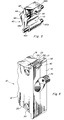
- the snap-in mountable circuit breaker.of this invention will be described below with respect to a preferred embodiment shown in the appended drawing.
- the circuit breaker operating mechanism contained in the circuit breaker case is not shown.
- the operating mechanism forms no significant part of the present invention, which is directed to the snap-in mounting subassembly.
- a suitable circuit breaker operating mechanism for the breaker of this invention is shown in detail in the present inventor's U.S. patent application Ser. No. 486,716, filed April 20, 1983, titled CIRCUIT BREAKER, and commonly assigned with the present invention.
- the disclosure of said application Ser. No. 486,716 is incorporated herein by reference in its entirety, as though set forth in full below.
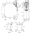
- a circuit breaker case is formed from two case halves; for convenience, but not by way of limitation, these are referred to below as the left case half 12 and right case half 14, respectively.
- a cover plate, generally designated 16 is composed of two complementary halves integrally formed with case halves 12 and 14, respectively. It is advantageous to form the cover plate 16 as an integral part of the breaker case 10 in order to provide additional room in the breaker case for the component parts of the snap-in mounting assembly without requiring significant modifications to the portions of the breaker case that are designed to accommodate the operating mechanism. Thus, by forming the cover plate as an integral part of the breaker case, additional space is created within the case to accommodate the recesses and the openings needed to mount the component parts of the snap-in mounting assembly.
- the breaker case 10 is generally hexahedronally shaped and includes portions which, for convenient reference but not by way of limitation, are designated top end portion 18 and bottom end portion end 20, respectively.
- Electrical terminals 22 and 24 extend outwardly from the rear of the breaker case 10 (i.e. opposite the front portion of the case incorporating the cover plate 16).
- a handle member 26 extends outwardly from the cover plate 16. When the breaker is mounted in a panel, handle 26 is accessible for manually opening and closing the breaker.
- the circuit breaker of this invention is intended to be mounted in a panel that is dimensioned to be slightly larger than the outside dimensions of the breaker case (not including the overlap of the cover plate).
- the long dimension of the panel opening (the distance from top to bottom) is significantly greater than the top to bottom case dimension.
- the end portions 18 and 20 are bevelled outwardly at regiors 28 and 30, respectively, adjacent the front portion of the case.
- Opening 32 is formed in the top end 18 of case 10 in the region adjacent the underside 17 of cover plate 16. Opening 32 communicates with an elongated spring mounting channel 38 that extends inwardly of the case. Opening 32 is formed and defined by cut-away portions 32a and 32b in the left case half 12 and right case half 14, respectively.
- Spring mounting channel 38 is formed and defined by recesses 38a and 38b formed in left case half 12 and right case half 14, respectively.
- Intermediate opening 32 and channel 38 are recesses or guide channels 34a and 34b formed in case halves 12 and 14, respectively.
- a cylindrical recess or mounting hole 36a is located rearwardly of guide channel 34a in the left case half 12.
- a corresponding cylindrical mounting hole or recess 36b is located rearwardly of guide channel 34b in right case half 14.
- FIGS. 3-5 show in detail the rigid locking dog member 40 that is disposed in the opening 32 of the assembled breaker case.
- the locking dog 40 may advantageously and preferably be made of a molded thermoplastic material. The principal requirements are that the material be relatively strong and unyielding under pressure, such as that which would be applied by a technician pushing clip on leads onto the terminals 22 and 24 of a panel mounted breaker.
- the locking dog 40 has a cammed outer surface 42 which may advantageously, but not necessarily, have a serrated face portion 44 to provide greater gripping power against the panel opening edge, as will be described in more detail below.
- a first set of lugs or pivot pins 46a, 46b extend outwardly from the sides of locking dog member 40 adjacent one end portion thereof.
- a second set of lugs or guide pins 48a, 48b extend outwardly from the sides of locking dog member 40 adjacent the other end portion thereof.
- a mounting lug 50 extends from the front inner face 41 of the locking dog member 40 adjacent the same end portion from which guide pins 48 extend.
- Pivot pins 46 seat in corresponding openings 36 in the assembled breaker case to define a pivot axis about which locking dog member 40 is rotatable.
- Guide pins 48 seat in and are moveable in guide channel 34 in the assembled breaker case. Rotational movement of the locking dog member 40 is limited to the amount which guide pins 48 are moveable in guide channel 34.
- the primary function of guide channels 34 and associated guide pins 46 is to prevent excessive outward pivotal movement of locking dog member 40.
- the locking dog member 40 is normally biased outwardly by bias means 52, in the form of a compression spring located in bias spring mounting channel 38.
- bias means 52 in the form of a compression spring located in bias spring mounting channel 38.
- One end of compression spring 52 rests against.an inner wall of recess 38; the other, free end portion of spring 52 mounts on spring mounting lug 50 to normally urge locking dog member 40 outwardly (in a counterclockwise direction of rotation about pivot pins 46, in FIG. 1).
- the snap-in panel mount circuit breaker of this invention is inserted into the panel opening from the front. As the breaker is inserted, the top edge of the panel opening contacts cammed surface 42. As the breaker is inserted further, the locking dog member 40 yields against the panel opening edge and pivots about pivot axis 46 (in a clockwise direction in FIG. 1) against the biasing force of spring 52. When the breaker is pushed all the way into the panel opening, until the under surface 17 of cover plate 16 rests against the panel face, cam face 44 engages the panel. opening edge. The locking dog 40, which is biased outwardly by spring 52, thereafter locks the circuit breaker in place in the panel opening.
- cover plate portion 16 is provided with a slot or groove 54 that extends from the outer edge of the cover plate toward and into opening 32.
- a face portion 43 of locking dog 40 lies in the path of slot or groove 54.
- a flat bladed tool of any suitable type may be inserted into the groove 5 4 sufficiently to engage surface 43 and urge locking dog 40 against the biasing force of spring 52. If sufficient force is exerted on the flat bladed tool to pivot the locking dog 40 about pivot axis 46 to its inner limit of travel (against the inner wall of guide channel 34 defined by recess 34a, 34b), the locking dog 40 will clear the edge of the panel opening, after which a twisting action on the flat bladed tool will cause the breaker to pop out of the panel.
Landscapes
- Engineering & Computer Science (AREA)
- Power Engineering (AREA)
- Breakers (AREA)
- Lock And Its Accessories (AREA)
- Switch Cases, Indication, And Locking (AREA)
Applications Claiming Priority (2)
| Application Number | Priority Date | Filing Date | Title |
|---|---|---|---|
| US624296 | 1984-06-25 | ||
| US06/624,296 US4587391A (en) | 1984-06-25 | 1984-06-25 | Snap in panel mounted circuit breaker |
Publications (2)
| Publication Number | Publication Date |
|---|---|
| EP0167336A2 true EP0167336A2 (fr) | 1986-01-08 |
| EP0167336A3 EP0167336A3 (fr) | 1988-08-10 |
Family
ID=24501432
Family Applications (1)
| Application Number | Title | Priority Date | Filing Date |
|---|---|---|---|
| EP85304506A Withdrawn EP0167336A3 (fr) | 1984-06-25 | 1985-06-25 | Interrupteur enciquetable monté dans une plaque |
Country Status (8)
| Country | Link |
|---|---|
| US (1) | US4587391A (fr) |
| EP (1) | EP0167336A3 (fr) |
| JP (1) | JPS61114432A (fr) |
| CA (1) | CA1266291A (fr) |
| DK (1) | DK287985A (fr) |
| ES (1) | ES296191Y (fr) |
| GR (1) | GR851542B (fr) |
| PT (1) | PT80709B (fr) |
Cited By (1)
| Publication number | Priority date | Publication date | Assignee | Title |
|---|---|---|---|---|
| EP0692854A1 (fr) * | 1994-07-07 | 1996-01-17 | Otis Elevator Company | Composant d'ascenceur protégé contre le vandalisme |
Families Citing this family (6)
| Publication number | Priority date | Publication date | Assignee | Title |
|---|---|---|---|---|
| DE8802459U1 (de) * | 1988-02-25 | 1988-04-21 | Ellenberger & Poensgen GmbH, 90518 Altdorf | Gehäuse für ein elektrisches Gerät |
| DE8909831U1 (de) * | 1989-08-16 | 1990-12-20 | Siemens AG, 80333 München | Hilfsschalteraufsatzblock |
| US5205502A (en) * | 1991-09-26 | 1993-04-27 | Rockwell International Corporation | Aviation electronics instrument latching swing handle |
| FR2744560B1 (fr) * | 1996-02-02 | 1998-03-27 | Schneider Electric Sa | Dispositif de commande ou de signalisation tel qu'un bouton-poussoir |
| CN107833799B (zh) * | 2017-10-26 | 2024-09-20 | 上海良信电器股份有限公司 | 一种插入式断路器的固定及解锁机构 |
| US20250232938A1 (en) * | 2024-01-16 | 2025-07-17 | Eaton Intelligent Power Limited | Universal circuit interrupter mounting assemblies |
Family Cites Families (23)
| Publication number | Priority date | Publication date | Assignee | Title |
|---|---|---|---|---|
| US1177923A (en) * | 1915-07-29 | 1916-04-04 | Philips Brinton Company | Cap for electric-circuit interrupters. |
| FR798431A (fr) * | 1935-02-04 | 1936-05-16 | Dispositif de prise de courant à fiches pour plafond | |
| US2223673A (en) * | 1937-05-03 | 1940-12-03 | R B M Mfg Company | Push button switch |
| US2444888A (en) * | 1944-12-12 | 1948-07-06 | H A Douglas Mfg Co | Coupling |
| US2703662A (en) * | 1949-01-11 | 1955-03-08 | Gen Motors Corp | Switch housing retaining means |
| FR75346E (fr) * | 1959-03-16 | 1961-06-09 | Prec Mecanique Labinal | Perfectionnements apportés aux interrupteurs |
| US3412225A (en) * | 1965-07-12 | 1968-11-19 | Robertshaw Controls Co | Switch with hinged switch base and cover |
| NL135416C (fr) * | 1967-07-31 | |||
| US3708640A (en) * | 1971-07-26 | 1973-01-02 | Korry Mfg Co | Front-mounted, clamp-to-hold electrical cartridge with swing-aside, push-to-test cap thereon |
| US3701870A (en) * | 1971-09-20 | 1972-10-31 | Carling Electric Inc | Switch case construction |
| DE2430707C3 (de) * | 1974-06-26 | 1986-01-02 | Brown, Boveri & Cie Ag, 6800 Mannheim | Elektrisches Einbaugerät |
| US3950066A (en) * | 1975-01-02 | 1976-04-13 | Leviton Manufacturing Co., Inc. | Covered electrical receptacle with snap-in mounting |
| US3987265A (en) * | 1975-03-17 | 1976-10-19 | Cutler-Hammer, Inc. | Snap-in assembly for mounting devices in a support panel aperture |
| SU603018A1 (ru) * | 1976-12-20 | 1978-04-15 | Предприятие П/Я А-7374 | Контактный блок электрического аппарата |
| IT1094110B (it) * | 1977-04-29 | 1985-07-26 | Rau Swf Autozubehoer | Dispositivo di fissaggio per interruttori |
| JPS587942Y2 (ja) * | 1977-06-29 | 1983-02-12 | 株式会社河合楽器製作所 | 電気部品取付装置 |
| DE2734275C3 (de) * | 1977-07-29 | 1980-05-14 | Rudolf Schadow Gmbh, 1000 Berlin | Schiebetastenschalter |
| US4211905A (en) * | 1979-02-14 | 1980-07-08 | Stackpole Components Company | Slide switch assembly for mounting in a panel |
| DE2915333C2 (de) * | 1979-04-14 | 1984-02-09 | Becker Autoradiowerk Gmbh, 7516 Karlsbad | Festhaltevorrichtung an Autoradiogeräten |
| JPS6136020Y2 (fr) * | 1980-06-09 | 1986-10-20 | ||
| US4434339A (en) * | 1980-10-11 | 1984-02-28 | Nihon Kaiheiki Kogyo Kabushiki Kaisha | Mounting frame equipped wth decorative plate for mounting switch or the like |
| JPS57180919U (fr) * | 1981-05-13 | 1982-11-16 | ||
| DE3145070A1 (de) * | 1981-11-13 | 1983-06-01 | Rafi Gmbh & Co Elektrotechnische Spezialfabrik, 7981 Berg | "drucktaster fuer schalttafeln" |
-
1984
- 1984-06-25 US US06/624,296 patent/US4587391A/en not_active Expired - Lifetime
-
1985
- 1985-06-20 CA CA000484704A patent/CA1266291A/fr not_active Expired - Fee Related
- 1985-06-24 GR GR851542A patent/GR851542B/el unknown
- 1985-06-25 DK DK287985A patent/DK287985A/da not_active Application Discontinuation
- 1985-06-25 PT PT80709A patent/PT80709B/pt unknown
- 1985-06-25 EP EP85304506A patent/EP0167336A3/fr not_active Withdrawn
- 1985-06-25 ES ES1985296191U patent/ES296191Y/es not_active Expired
- 1985-10-29 JP JP60240704A patent/JPS61114432A/ja active Granted
Cited By (2)
| Publication number | Priority date | Publication date | Assignee | Title |
|---|---|---|---|---|
| EP0692854A1 (fr) * | 1994-07-07 | 1996-01-17 | Otis Elevator Company | Composant d'ascenceur protégé contre le vandalisme |
| US5584366A (en) * | 1994-07-07 | 1996-12-17 | Otis Elevator Company | Vandal-safe system for fastening an electrical component on a supporting wall |
Also Published As
| Publication number | Publication date |
|---|---|
| EP0167336A3 (fr) | 1988-08-10 |
| GR851542B (fr) | 1985-11-25 |
| DK287985D0 (da) | 1985-06-25 |
| ES296191U (es) | 1987-12-16 |
| PT80709B (en) | 1986-11-10 |
| CA1266291A (fr) | 1990-02-27 |
| JPH0319661B2 (fr) | 1991-03-15 |
| ES296191Y (es) | 1988-05-16 |
| US4587391A (en) | 1986-05-06 |
| DK287985A (da) | 1985-12-26 |
| JPS61114432A (ja) | 1986-06-02 |
| PT80709A (en) | 1985-07-01 |
Similar Documents
| Publication | Publication Date | Title |
|---|---|---|
| US4398073A (en) | Fastening device for a switch | |
| US4609119A (en) | Retaining device for mounting electrical units | |
| US3453408A (en) | Snap-in mounting device for circuit breakers | |
| US5550322A (en) | Electrical outlet box | |
| US3125366A (en) | Latch mechanism | |
| US4454565A (en) | Adapter plate assembly for circuit breaker | |
| US4437720A (en) | Screwless terminal | |
| EP0167336A2 (fr) | Interrupteur enciquetable monté dans une plaque | |
| US4066838A (en) | Apparatus for detachably mounting electrical assembly units to supporting panels | |
| KR100200008B1 (ko) | 일체식 스위치를 갖춘 오버센터 토글래치 | |
| KR940004889A (ko) | 볼트 체결형 전기 코넥터 | |
| GB2298973A (en) | Terminal structure for a wiring device | |
| KR200142554Y1 (ko) | 글로브 박스 힌지구조 | |
| EP0886947B1 (fr) | Courvercle de boitier avec element d'assemblage et de blocage | |
| GB2240879A (en) | Electric switch | |
| GB2108318A (en) | Switch with a case provided with an attaching device | |
| CN221354731U (zh) | 电源模块及插框组件 | |
| JPH0554930A (ja) | コンセント | |
| US3283110A (en) | Half-width circuit breaker modification for full width load centers | |
| KR0136721Y1 (ko) | 전자제품의 전원스위치 동작장치 | |
| JP3508141B2 (ja) | 電気機器の取付け構造 | |
| CA2043750C (fr) | Armature combinee d'interrupteur a bouton-poussoir et a verrou | |
| JP3990759B2 (ja) | 電気配線箱の施錠装置 | |
| GB2114370A (en) | Electrical leaf switch mounting construction | |
| JP2857732B2 (ja) | 電気コネクタ |
Legal Events
| Date | Code | Title | Description |
|---|---|---|---|
| PUAI | Public reference made under article 153(3) epc to a published international application that has entered the european phase |
Free format text: ORIGINAL CODE: 0009012 |
|
| AK | Designated contracting states |
Designated state(s): BE CH DE FR GB IT LI LU NL |
|
| PUAL | Search report despatched |
Free format text: ORIGINAL CODE: 0009013 |
|
| AK | Designated contracting states |
Kind code of ref document: A3 Designated state(s): BE CH DE FR GB IT LI LU NL |
|
| 17P | Request for examination filed |
Effective date: 19890123 |
|
| 17Q | First examination report despatched |
Effective date: 19901029 |
|
| STAA | Information on the status of an ep patent application or granted ep patent |
Free format text: STATUS: THE APPLICATION HAS BEEN WITHDRAWN |
|
| 18W | Application withdrawn |
Withdrawal date: 19910212 |
|
| R18W | Application withdrawn (corrected) |
Effective date: 19910212 |
|
| RIN1 | Information on inventor provided before grant (corrected) |
Inventor name: HARPER, GEORGE S. |