EP0167345A1 - Dispositif à crampons - Google Patents
Dispositif à crampons Download PDFInfo
- Publication number
- EP0167345A1 EP0167345A1 EP85304539A EP85304539A EP0167345A1 EP 0167345 A1 EP0167345 A1 EP 0167345A1 EP 85304539 A EP85304539 A EP 85304539A EP 85304539 A EP85304539 A EP 85304539A EP 0167345 A1 EP0167345 A1 EP 0167345A1
- Authority
- EP
- European Patent Office
- Prior art keywords
- elements
- arrangement according
- waves
- clamping
- contacting
- Prior art date
- Legal status (The legal status is an assumption and is not a legal conclusion. Google has not performed a legal analysis and makes no representation as to the accuracy of the status listed.)
- Withdrawn
Links
- 241000270295 Serpentes Species 0.000 claims abstract description 12
- UONOETXJSWQNOL-UHFFFAOYSA-N tungsten carbide Chemical compound [W+]#[C-] UONOETXJSWQNOL-UHFFFAOYSA-N 0.000 claims abstract description 8
- 238000012876 topography Methods 0.000 claims abstract description 6
- WFKWXMTUELFFGS-UHFFFAOYSA-N tungsten Chemical compound [W] WFKWXMTUELFFGS-UHFFFAOYSA-N 0.000 claims abstract description 5
- 229910052721 tungsten Inorganic materials 0.000 claims abstract description 5
- 239000010937 tungsten Substances 0.000 claims abstract description 5
- 230000000694 effects Effects 0.000 claims abstract description 3
- MCMNRKCIXSYSNV-UHFFFAOYSA-N Zirconium dioxide Chemical compound O=[Zr]=O MCMNRKCIXSYSNV-UHFFFAOYSA-N 0.000 claims description 4
- 239000000463 material Substances 0.000 claims description 4
- 239000012768 molten material Substances 0.000 claims description 2
- 238000009760 electrical discharge machining Methods 0.000 claims 1
- 230000013011 mating Effects 0.000 description 6
- 239000002245 particle Substances 0.000 description 4
- 230000015572 biosynthetic process Effects 0.000 description 2
- 238000000576 coating method Methods 0.000 description 2
- 239000007788 liquid Substances 0.000 description 2
- 238000002844 melting Methods 0.000 description 2
- 230000008018 melting Effects 0.000 description 2
- 230000004048 modification Effects 0.000 description 2
- 238000012986 modification Methods 0.000 description 2
- 238000007788 roughening Methods 0.000 description 2
- 238000005507 spraying Methods 0.000 description 2
- 229910000831 Steel Inorganic materials 0.000 description 1
- PNEYBMLMFCGWSK-UHFFFAOYSA-N aluminium oxide Inorganic materials [O-2].[O-2].[O-2].[Al+3].[Al+3] PNEYBMLMFCGWSK-UHFFFAOYSA-N 0.000 description 1
- 230000000712 assembly Effects 0.000 description 1
- 238000000429 assembly Methods 0.000 description 1
- 239000011248 coating agent Substances 0.000 description 1
- 239000002360 explosive Substances 0.000 description 1
- 230000003116 impacting effect Effects 0.000 description 1
- 230000002401 inhibitory effect Effects 0.000 description 1
- 229910052751 metal Inorganic materials 0.000 description 1
- 239000002184 metal Substances 0.000 description 1
- 150000002739 metals Chemical class 0.000 description 1
- 238000000034 method Methods 0.000 description 1
- 239000000203 mixture Substances 0.000 description 1
- 239000011819 refractory material Substances 0.000 description 1
- 239000007921 spray Substances 0.000 description 1
- 239000010959 steel Substances 0.000 description 1
Images


Classifications
-
- G—PHYSICS
- G02—OPTICS
- G02B—OPTICAL ELEMENTS, SYSTEMS OR APPARATUS
- G02B6/00—Light guides; Structural details of arrangements comprising light guides and other optical elements, e.g. couplings
- G02B6/44—Mechanical structures for providing tensile strength and external protection for fibres, e.g. optical transmission cables
- G02B6/4439—Auxiliary devices
- G02B6/4459—Ducts; Conduits; Hollow tubes for air blown fibres
- G02B6/4461—Articulated
-
- A—HUMAN NECESSITIES
- A61—MEDICAL OR VETERINARY SCIENCE; HYGIENE
- A61B—DIAGNOSIS; SURGERY; IDENTIFICATION
- A61B90/00—Instruments, implements or accessories specially adapted for surgery or diagnosis and not covered by any of the groups A61B1/00 - A61B50/00, e.g. for luxation treatment or for protecting wound edges
- A61B90/50—Supports for surgical instruments, e.g. articulated arms
-
- F—MECHANICAL ENGINEERING; LIGHTING; HEATING; WEAPONS; BLASTING
- F16—ENGINEERING ELEMENTS AND UNITS; GENERAL MEASURES FOR PRODUCING AND MAINTAINING EFFECTIVE FUNCTIONING OF MACHINES OR INSTALLATIONS; THERMAL INSULATION IN GENERAL
- F16M—FRAMES, CASINGS OR BEDS OF ENGINES, MACHINES OR APPARATUS, NOT SPECIFIC TO ENGINES, MACHINES OR APPARATUS PROVIDED FOR ELSEWHERE; STANDS; SUPPORTS
- F16M11/00—Stands or trestles as supports for apparatus or articles placed thereon ; Stands for scientific apparatus such as gravitational force meters
- F16M11/02—Heads
- F16M11/04—Means for attachment of apparatus; Means allowing adjustment of the apparatus relatively to the stand
- F16M11/06—Means for attachment of apparatus; Means allowing adjustment of the apparatus relatively to the stand allowing pivoting
- F16M11/10—Means for attachment of apparatus; Means allowing adjustment of the apparatus relatively to the stand allowing pivoting around a horizontal axis
-
- F—MECHANICAL ENGINEERING; LIGHTING; HEATING; WEAPONS; BLASTING
- F16—ENGINEERING ELEMENTS AND UNITS; GENERAL MEASURES FOR PRODUCING AND MAINTAINING EFFECTIVE FUNCTIONING OF MACHINES OR INSTALLATIONS; THERMAL INSULATION IN GENERAL
- F16M—FRAMES, CASINGS OR BEDS OF ENGINES, MACHINES OR APPARATUS, NOT SPECIFIC TO ENGINES, MACHINES OR APPARATUS PROVIDED FOR ELSEWHERE; STANDS; SUPPORTS
- F16M11/00—Stands or trestles as supports for apparatus or articles placed thereon ; Stands for scientific apparatus such as gravitational force meters
- F16M11/20—Undercarriages with or without wheels
- F16M11/2007—Undercarriages with or without wheels comprising means allowing pivoting adjustment
- F16M11/2021—Undercarriages with or without wheels comprising means allowing pivoting adjustment around a horizontal axis
-
- F—MECHANICAL ENGINEERING; LIGHTING; HEATING; WEAPONS; BLASTING
- F16—ENGINEERING ELEMENTS AND UNITS; GENERAL MEASURES FOR PRODUCING AND MAINTAINING EFFECTIVE FUNCTIONING OF MACHINES OR INSTALLATIONS; THERMAL INSULATION IN GENERAL
- F16M—FRAMES, CASINGS OR BEDS OF ENGINES, MACHINES OR APPARATUS, NOT SPECIFIC TO ENGINES, MACHINES OR APPARATUS PROVIDED FOR ELSEWHERE; STANDS; SUPPORTS
- F16M11/00—Stands or trestles as supports for apparatus or articles placed thereon ; Stands for scientific apparatus such as gravitational force meters
- F16M11/20—Undercarriages with or without wheels
- F16M11/24—Undercarriages with or without wheels changeable in height or length of legs, also for transport only, e.g. by means of tubes screwed into each other
- F16M11/40—Undercarriages with or without wheels changeable in height or length of legs, also for transport only, e.g. by means of tubes screwed into each other by means of coilable or bendable legs or spiral shaped legs
-
- F—MECHANICAL ENGINEERING; LIGHTING; HEATING; WEAPONS; BLASTING
- F16—ENGINEERING ELEMENTS AND UNITS; GENERAL MEASURES FOR PRODUCING AND MAINTAINING EFFECTIVE FUNCTIONING OF MACHINES OR INSTALLATIONS; THERMAL INSULATION IN GENERAL
- F16M—FRAMES, CASINGS OR BEDS OF ENGINES, MACHINES OR APPARATUS, NOT SPECIFIC TO ENGINES, MACHINES OR APPARATUS PROVIDED FOR ELSEWHERE; STANDS; SUPPORTS
- F16M13/00—Other supports for positioning apparatus or articles; Means for steadying hand-held apparatus or articles
-
- F—MECHANICAL ENGINEERING; LIGHTING; HEATING; WEAPONS; BLASTING
- F16—ENGINEERING ELEMENTS AND UNITS; GENERAL MEASURES FOR PRODUCING AND MAINTAINING EFFECTIVE FUNCTIONING OF MACHINES OR INSTALLATIONS; THERMAL INSULATION IN GENERAL
- F16M—FRAMES, CASINGS OR BEDS OF ENGINES, MACHINES OR APPARATUS, NOT SPECIFIC TO ENGINES, MACHINES OR APPARATUS PROVIDED FOR ELSEWHERE; STANDS; SUPPORTS
- F16M13/00—Other supports for positioning apparatus or articles; Means for steadying hand-held apparatus or articles
- F16M13/02—Other supports for positioning apparatus or articles; Means for steadying hand-held apparatus or articles for supporting on, or attaching to, an object, e.g. tree, gate, window-frame, cycle
- F16M13/022—Other supports for positioning apparatus or articles; Means for steadying hand-held apparatus or articles for supporting on, or attaching to, an object, e.g. tree, gate, window-frame, cycle repositionable
-
- F—MECHANICAL ENGINEERING; LIGHTING; HEATING; WEAPONS; BLASTING
- F21—LIGHTING
- F21V—FUNCTIONAL FEATURES OR DETAILS OF LIGHTING DEVICES OR SYSTEMS THEREOF; STRUCTURAL COMBINATIONS OF LIGHTING DEVICES WITH OTHER ARTICLES, NOT OTHERWISE PROVIDED FOR
- F21V21/00—Supporting, suspending, or attaching arrangements for lighting devices; Hand grips
- F21V21/14—Adjustable mountings
- F21V21/32—Flexible tubes
-
- A—HUMAN NECESSITIES
- A61—MEDICAL OR VETERINARY SCIENCE; HYGIENE
- A61B—DIAGNOSIS; SURGERY; IDENTIFICATION
- A61B17/00—Surgical instruments, devices or methods
- A61B17/28—Surgical forceps
- A61B17/29—Forceps for use in minimally invasive surgery
- A61B2017/2901—Details of shaft
- A61B2017/2905—Details of shaft flexible
Definitions
- the present invention relates to clamping arrangements, in particular for enabling the adjustable clamping of components.
- Supports for surgical instruments and tools such as lighting units and microscopes is effected by a variety of multi-arm or multi-element devices.
- Such devices include a string of arms or elements with a holder at one end for supporting the tool or instrument and allow great versatility in the positioning of the holder. Once the holder has been positioned as required, adjoining elements or arms are clamped together under pressure to ensure that the holder remains in the required position.
- British Patent Specification No. 1,156,772 discloses a clamping arrangement in which the mating surfaces of two relatively slidable plates to be clamped together are provided with regularly arranged relatively large mating projections and depressions. With this arrangement, the two members can only be clamped together in a limited number of selected relative positions and so is unsatisfactory for use in situations where the two members are required to be clamped together in any relative positions. Furthermore, with regularly arranged projections and depressions, the two members must be rotated relatively to one another in alignment along a selected locus if a good clamping action is to be achieved.
- a clamping arrangement comprising two relatively slidable elements arranged to be urged together to lock the two elements against relative sliding movement, the contacting surfaces of each element having a topography consisting of randomly positioned smooth surfaced waves, the majority of waves falling into one of two different size ranges, the ratio of the two size ranges being greater than 70:1, whereby to allow relative sliding of the elements when the pressure urging the members together is relaxed.
- a clamping arrangement comprising two contacting members movable relative to one another, the contacting surface of each member having a randomly undulating but substantially smooth surface profile.
- a snake clamping assembly comprising a plurality of elements threaded onto a tensionable filament, each element having a spherical head at one axial end and a corresponding part-spherical recess at its opposite axial end, the head of each element being arranged to engage the recess of its adjacent element, the contacting surfaces of said elements having a randomly undulating but substantially smooth profile, and tensioning means for tensioning the threaded elements together along the filament, whereby to lock the elements in the relative attitudes in which they lie at that time.
- each clamping arrangement comprising at least two members urged into contact with one another and wherein the contacting surfaces of each said member comprises a randomly undulating but substantially smooth surface.
- the 'snake' clamping assembly shown in Figure 1 comprises a holder 2 supported by a chain 4 of elements 6 from a support member 8.
- the holder 2 is linked to a screw-threaded rod 10 by a multi- stranded wire cable 12, and the elements 6, each of which has a central bore, are threaded onto the cable 12 (see Figure 2).
- the end element 6a of the chain 4 is arranged to abut a stop member 14 rigid with the support member 8.
- the rod 10 slidably carries an abutment member 18 and is in screw-threaded engagement with a knurled, internally screw-threaded, fastener 18.
- the facing surfaces of the stop member 14 and the abutment member 18 are mutually inclined and are engaged by a wedge-shaped cam member 20.
- the cam member 20 has a cantilevered portion 20a which extends along the outer surface of the stop member 14.
- the cantilevered portion 20a is traversed by, and in screw-threaded engagement with, a winged bolt 22 which has its free end in abutment with the outer surface of the stop member 14.
- the winged bolt 22 is loosened to allow the wedge-shaped cam member 20 to slide in a sense in which the two members 14 and 16 can move towards one another. This reduces the tension in the cable 12 and so allows the individual elements to move relative to one another. In this state the holder 2 can be positioned as required. Once the desired position for the holder 2 is reached, the winged bolt 22 is tightened. When being tightened, the bolt 22 bears against the member 14 to cause the cam member 20 to slide between the members 14 and 16 and so urge them apart by cam action. As the member 16 is displaced away from the member 14, it engages the fastener 18 which in turn engages the rod 10 and so displaces the rod 10.
- the cable 12, which in turn is secured to the rod 10, is, thus tensioned to draw all the elements 6.together and in particular the end element 6a into tight abutment with the member 14.
- the elements 6 are thus clamped together to hold the holder 2 in the desired position and attitude.
- Each element 6 has an elongate cylindrical body 6C carrying a spherical head 6B at one axial end and is provided with a part-spherical recess 6D at its other axial end.
- the elements 6 are placed end to end so that the head 6B of one element matingly engages the part-spherical recess 6D in the adjacent element.
- the adjacent elements 6 When the cable 12 is slack, the adjacent elements 6 can be displaced into relatively inclined positions. When the cable 12 is tensioned, the mating surfaces of adjacent elements provide a relatively large area of contact between elements 6 and so the frictional force inhibiting relative movement is relatively large.
- the mating contacting surfaces of the elements 6 are treated with a tungsten carbide electrode.
- the treatment involves the creation of a series of explosive sparks between the element and the tungsten carbide electrode. Because of the ionisation of the gas in the gap between the electrode and the element, minute particles of tungsten and tungsten carbide are carried across the gap and impinge upon the surface of the member 6 to be coated. This surface becomes locally molten at the time and so the particle becomes embedded in the surface.
- the adhesion of particles deposited in this random way is particularly good and the deposited particles take the form of smooth curved flattish undulations with no rough edges.
- the scale of the surface in Figure 5 is approximately 30 ⁇ m (0.03 mm) to the centimetre, while the scale of the surface of Figure 6 is approximately 15 ⁇ m (0.015 mm) to the centimetre.
- the topography consists of a plurality of randomly positioned different sized craters with a scattering of smaller sized globules.
- the surface appears akin to that of a choppy sea in motion frozen at a selected instant in time.
- the surface comprises a mixture of large and small waves, the large waves corresponding to the craters and the small waves corresponding to the globules. It will be apparent that the surfaces of both the large and small waves are generally smooth.
- the large waves have an average pitch (diameter) which can vary in the range of from 50 to 150 ⁇ m (0.05 to 0.15 mm).
- the small waves have an average pitch (diameter) which can vary in the range of from 0.3 to 0.7 ⁇ m (0.0003 to 0.0007 mm).
- the ratio of the size of the large waves to small waves can vary over the range of from 500:1 to 70:1.
- the peak height of the waves (crest to trough) can be up to 8 vm (0.008 mm).
- topographic features results from local melting by the molten droplets impacting the surface and spreading laterally to produce the smooth areas. Breakup of the molten material around the periphery gives rise to the formation of small globules.
- the smooth areas are seen to partially cover a microscopically much rougher underlying surface structure and in some cases to have been deposited on top of other previously formed smooth areas.
- the microscopically rougher surface consists of small craters and locally melted and resolidified material and has a generally rounded topography.
- the smooth nature of the surfaces enables two similar contacting surfaces to slide easily relative to one another in the absence of a load or pressure.
- the peaks of the waves in one surface lock into the troughs of the waves in the other surface (and vice versa) in a random fashion and this provides a very rigid clamping action to inhibit relative sliding between the surfaces.
- This clamping action is more effective because as indicated hereinbefore the flattish undulations on one of the contacting surfaces of one element fall into the hollows between the flattish undulations on the other element and so if relative movement between the contacting surfaces is to take place, not only must frictional forces be overcome but also the forces required in stretching the cable to allow the undulations of one element to ride over those of the other element.
- the average height of the undulations is arranged to be in excess of 0.005 mm and the average surface area of each undulation is arranged to be less than 0.3 mm 2.
- Liquid spray coating processes involve using materials of high melting point which are then liquified in or at the exit of a spray gun. Such coatings all have smooth globules and rely for adhesion on the fact that they are just molten when they reach the surface onto which they cling.
- the elements 6 could each be made of allumina and the coating surfaces sandblasted to produce a surface structure having the required characteristics.
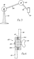
- the multi-arm support shown in Figure 3 includes an upstanding support member 50 supporting a holder 52 through two linked arms 54 and 56.
- One clamping assembly 60 couples the arms 54 and 56 while another clamping assembly 58 couples the arm 54 to the upstanding support 50.
- the two clamping assemblies 58 and 60 are similar and so only one is shown in more detail in Figure 4.
- the arms 54 and 56 terminate in respective cup-shaped end portions 54A and 56A and are so orientated that the rims of the end portions face one another.
- a disc 62 is located between the facing rims.
- a bolt 64 passes centrally through the two cup-shaped end members 54A and 56A and a wing nut 56 screw-threadedly engages the nut 64. By turning the wing nut 66 the clamping assembly can be tightened or loosened.
- the mating surfaces of the cup-shaped end portions 54 and 56 and the disc 62 all have surface profiles such as are described in connection with the mating surfaces of the elements 6 of the 'snake' clamping assembly of Figure 2.
- the materials of the surfaces can also be the same.
- the individual links instead of defining balls and sockets to provide the contacting surfaces, can take the form of a series of cylindrical members in which each alternate member is positioned at right angles to each intervening member.
- each intervening member is axially threaded and each alternate member diagonally threaded to accommodate the cable 12.
Landscapes
- Engineering & Computer Science (AREA)
- General Engineering & Computer Science (AREA)
- Mechanical Engineering (AREA)
- Health & Medical Sciences (AREA)
- Surgery (AREA)
- Physics & Mathematics (AREA)
- Life Sciences & Earth Sciences (AREA)
- Heart & Thoracic Surgery (AREA)
- General Health & Medical Sciences (AREA)
- Biomedical Technology (AREA)
- Oral & Maxillofacial Surgery (AREA)
- Medical Informatics (AREA)
- Molecular Biology (AREA)
- Animal Behavior & Ethology (AREA)
- Pathology (AREA)
- Public Health (AREA)
- Veterinary Medicine (AREA)
- Nuclear Medicine, Radiotherapy & Molecular Imaging (AREA)
- General Physics & Mathematics (AREA)
- Optics & Photonics (AREA)
- Clamps And Clips (AREA)
- Details Of Measuring And Other Instruments (AREA)
Applications Claiming Priority (2)
| Application Number | Priority Date | Filing Date | Title |
|---|---|---|---|
| GB08417260A GB2166190A (en) | 1984-07-06 | 1984-07-06 | Clamping arrangements |
| GB8417260 | 1984-07-06 |
Publications (1)
| Publication Number | Publication Date |
|---|---|
| EP0167345A1 true EP0167345A1 (fr) | 1986-01-08 |
Family
ID=10563503
Family Applications (1)
| Application Number | Title | Priority Date | Filing Date |
|---|---|---|---|
| EP85304539A Withdrawn EP0167345A1 (fr) | 1984-07-06 | 1985-06-26 | Dispositif à crampons |
Country Status (3)
| Country | Link |
|---|---|
| EP (1) | EP0167345A1 (fr) |
| JP (1) | JPS6192306A (fr) |
| GB (1) | GB2166190A (fr) |
Cited By (37)
| Publication number | Priority date | Publication date | Assignee | Title |
|---|---|---|---|---|
| FR2702952A1 (fr) * | 1993-03-29 | 1994-09-30 | Eier Kk | Appareil pour la fixation en position réglable d'un instrument chirurgical ou similaire. |
| WO1995010985A1 (fr) * | 1993-10-21 | 1995-04-27 | Ognier Jean Francois | Dispositif support pour instrument medical ou chirurgical |
| EP0684018A1 (fr) * | 1994-05-23 | 1995-11-29 | Bilbao Ortiz de Zarate, José Ramon | Système pour mettre en place les vertèbres cervicales par l'arrière |
| GB2307727A (en) * | 1995-12-01 | 1997-06-04 | Univ Southampton | Mounting device for medical tubing |
| US5649925A (en) * | 1994-05-13 | 1997-07-22 | Jose Vicente Barbera Alacreu | System for setting cervical vertebrae from behind |
| EP1011180A1 (fr) * | 1998-12-14 | 2000-06-21 | KA-TE System AG | Dispositif de réception des articles flexibles et allongés |
| EP0993806A3 (fr) * | 1998-09-15 | 2000-06-28 | Medtronic Inc. | Appareil d'immobilisation temporaire d'une zone locale de tissu |
| US6328688B1 (en) | 1995-09-20 | 2001-12-11 | Medtronic, Inc. | Method and apparatus for temporarily immobilizing a local area of tissue |
| WO2002002016A1 (fr) * | 2000-06-30 | 2002-01-10 | Abbott Laboratories | Pince de soutien chirurgicale |
| WO2002045782A1 (fr) * | 2000-12-09 | 2002-06-13 | Michael Schulze | Support de perfusion a monter sur des dispositifs soutenant un patient |
| EP1293165A1 (fr) * | 1996-04-26 | 2003-03-19 | United States Surgical Corporation | Ecarteur chirurgical |
| US6565582B2 (en) | 1995-02-24 | 2003-05-20 | Hearport, Inc. | Devices and methods for performing a vascular anastomosis |
| EP1323383A1 (fr) * | 1996-04-26 | 2003-07-02 | United States Surgical Corporation | Ecarteur chirurgical |
| WO2003030830A3 (fr) * | 2001-10-09 | 2003-10-16 | Endoscopic Technologies Inc | Procede et appareil permettant l'amelioration de la rigidite de l'ensemble de timonerie d'un bras souple |
| US6676597B2 (en) | 2001-01-13 | 2004-01-13 | Medtronic, Inc. | Method and device for organ positioning |
| US6709389B2 (en) | 1996-09-20 | 2004-03-23 | United States Surgical Corporation | Surgical apparatus and method |
| US6716163B2 (en) * | 2000-11-21 | 2004-04-06 | Nabil L. Muhanna | Surgical instrument holder |
| US6733445B2 (en) | 1996-04-26 | 2004-05-11 | United States Surgical Corporation | Surgical retractor |
| DE10355278A1 (de) * | 2003-11-19 | 2005-07-14 | Aesculap Ag & Co. Kg | Chirurgische Haltevorrichtung |
| US7137949B2 (en) | 2001-07-13 | 2006-11-21 | United States Surgical Corporation | Surgical instrument |
| EP1726867A3 (fr) * | 2005-05-26 | 2006-12-27 | Sherwood Services AG | Dispositif de serrage flexible pour dispositifs médicaux |
| US7189201B2 (en) | 1995-09-20 | 2007-03-13 | Medtronic, Inc. | Method and apparatus for temporarily immobilizing a local area of tissue |
| US7294104B2 (en) | 1998-01-23 | 2007-11-13 | United States Surgical Corporation | Surgical instrument holder |
| US7338434B1 (en) | 2002-08-21 | 2008-03-04 | Medtronic, Inc. | Method and system for organ positioning and stabilization |
| US7399272B2 (en) | 2004-03-24 | 2008-07-15 | Medtronic, Inc. | Methods and apparatus providing suction-assisted tissue engagement |
| US7494460B2 (en) | 2002-08-21 | 2009-02-24 | Medtronic, Inc. | Methods and apparatus providing suction-assisted tissue engagement through a minimally invasive incision |
| US7546993B1 (en) | 2008-03-25 | 2009-06-16 | Tyco Healthcare Group Lp | Flexible clamping apparatus for medical devices |
| US7794387B2 (en) | 2006-04-26 | 2010-09-14 | Medtronic, Inc. | Methods and devices for stabilizing tissue |
| US7980521B2 (en) | 2007-05-04 | 2011-07-19 | Tyco Healthcare Group Lp | Medical device safety support with infinite positioning |
| US8133039B2 (en) | 2009-01-26 | 2012-03-13 | Tyco Healthcare Group Lp | Mount for a compression control unit |
| USD659839S1 (en) | 2010-08-16 | 2012-05-15 | Tyco Healthcare Group Lp | Support for a pneumatic compression controller |
| CN101433497B (zh) * | 2007-11-08 | 2012-06-13 | 泰科保健集团有限合伙公司 | 可伸缩地调节的夹具 |
| USD675741S1 (en) | 2010-08-16 | 2013-02-05 | Covidien Lp | Pneumatic compression controller |
| US8696556B2 (en) | 2009-07-28 | 2014-04-15 | Endoscopic Technologies, Inc. | Tissue retractors with fluid evacuation/infusion and/or light emission capability |
| US10335280B2 (en) | 2000-01-19 | 2019-07-02 | Medtronic, Inc. | Method for ablating target tissue of a patient |
| CN110974354A (zh) * | 2019-12-26 | 2020-04-10 | 丽水市人民医院 | 一种动脉瘤夹把持钳 |
| CN120788482A (zh) * | 2025-09-05 | 2025-10-17 | 中国人民解放军总医院第一医学中心 | 脑室内镜导向定位装置 |
Families Citing this family (2)
| Publication number | Priority date | Publication date | Assignee | Title |
|---|---|---|---|---|
| GB2219439A (en) * | 1988-06-06 | 1989-12-06 | Gore & Ass | Flexible housing |
| JP2007070838A (ja) * | 2005-09-05 | 2007-03-22 | Shigeki Nakamura | 管材クランプの異径管対応構造 |
Citations (7)
| Publication number | Priority date | Publication date | Assignee | Title |
|---|---|---|---|---|
| GB1156772A (en) * | 1966-11-30 | 1969-07-02 | Albert Eric Gautier | Improvements in or relating to Joints Rigidly Connecting Two Rods or Tubes in Parallel or Angular Disposition. |
| DE1750252A1 (de) * | 1967-04-14 | 1972-02-17 | Polar Hydraulics Ltd | Instrumenten-Staender |
| GB1436703A (en) * | 1973-03-28 | 1976-05-26 | Fletcher F | Releasable joint |
| GB1462735A (en) * | 1974-05-06 | 1977-01-26 | Michelin & Cie | Pneumatic tyres |
| DE2514496B2 (de) * | 1974-04-04 | 1977-06-16 | Ausscheidung in: 25 59 399 Olympus Optical Co., Ltd., Tokio | Flexible haltevorrichtung |
| EP0094520A1 (fr) * | 1982-05-14 | 1983-11-23 | John Willy Höiseth | Dispositif pour le blocage de deux membres |
| CH640313A5 (de) * | 1978-09-13 | 1983-12-30 | Giulio Gentile | Klemmorgan. |
Family Cites Families (2)
| Publication number | Priority date | Publication date | Assignee | Title |
|---|---|---|---|---|
| GB1410714A (en) * | 1972-02-25 | 1975-10-22 | Plasty Spielzeug Gmbh Co Kg | Joints |
| GB1455656A (en) * | 1974-01-28 | 1976-11-17 | Brown L | Visor |
-
1984
- 1984-07-06 GB GB08417260A patent/GB2166190A/en not_active Withdrawn
-
1985
- 1985-06-26 EP EP85304539A patent/EP0167345A1/fr not_active Withdrawn
- 1985-07-05 JP JP60146889A patent/JPS6192306A/ja active Pending
Patent Citations (7)
| Publication number | Priority date | Publication date | Assignee | Title |
|---|---|---|---|---|
| GB1156772A (en) * | 1966-11-30 | 1969-07-02 | Albert Eric Gautier | Improvements in or relating to Joints Rigidly Connecting Two Rods or Tubes in Parallel or Angular Disposition. |
| DE1750252A1 (de) * | 1967-04-14 | 1972-02-17 | Polar Hydraulics Ltd | Instrumenten-Staender |
| GB1436703A (en) * | 1973-03-28 | 1976-05-26 | Fletcher F | Releasable joint |
| DE2514496B2 (de) * | 1974-04-04 | 1977-06-16 | Ausscheidung in: 25 59 399 Olympus Optical Co., Ltd., Tokio | Flexible haltevorrichtung |
| GB1462735A (en) * | 1974-05-06 | 1977-01-26 | Michelin & Cie | Pneumatic tyres |
| CH640313A5 (de) * | 1978-09-13 | 1983-12-30 | Giulio Gentile | Klemmorgan. |
| EP0094520A1 (fr) * | 1982-05-14 | 1983-11-23 | John Willy Höiseth | Dispositif pour le blocage de deux membres |
Cited By (64)
| Publication number | Priority date | Publication date | Assignee | Title |
|---|---|---|---|---|
| FR2702952A1 (fr) * | 1993-03-29 | 1994-09-30 | Eier Kk | Appareil pour la fixation en position réglable d'un instrument chirurgical ou similaire. |
| WO1995010985A1 (fr) * | 1993-10-21 | 1995-04-27 | Ognier Jean Francois | Dispositif support pour instrument medical ou chirurgical |
| FR2711506A1 (fr) * | 1993-10-21 | 1995-05-05 | Ognier Jean Francois | Dispositif support pour instrument médical ou chirurgical. |
| US5918844A (en) * | 1993-10-21 | 1999-07-06 | Ognier; Jean-Francois | Support device for medical or surgical instrument |
| US5649925A (en) * | 1994-05-13 | 1997-07-22 | Jose Vicente Barbera Alacreu | System for setting cervical vertebrae from behind |
| EP0684018A1 (fr) * | 1994-05-23 | 1995-11-29 | Bilbao Ortiz de Zarate, José Ramon | Système pour mettre en place les vertèbres cervicales par l'arrière |
| US6565582B2 (en) | 1995-02-24 | 2003-05-20 | Hearport, Inc. | Devices and methods for performing a vascular anastomosis |
| US6699257B2 (en) | 1995-02-24 | 2004-03-02 | Heartport, Inc | Devices and methods for performing a vascular anastomosis |
| US6334843B1 (en) | 1995-09-20 | 2002-01-01 | Medtronic, Inc. | Method and apparatus for temporarily immobilizing a local area of tissue |
| US6371906B1 (en) | 1995-09-20 | 2002-04-16 | Medtronic, Inc. | Method and apparatus for temporarily immobilizing a local area of tissue |
| US7445594B1 (en) | 1995-09-20 | 2008-11-04 | Medtronic, Inc. | Method and apparatus for temporarily immobilizing a local area of tissue |
| US6328688B1 (en) | 1995-09-20 | 2001-12-11 | Medtronic, Inc. | Method and apparatus for temporarily immobilizing a local area of tissue |
| US6464630B1 (en) | 1995-09-20 | 2002-10-15 | Medtronic, Inc. | Method and apparatus for temporarily immobilizing a local area of tissue |
| US6336898B1 (en) | 1995-09-20 | 2002-01-08 | Medtronic, Inc. | Method and apparatus for temporarily immobilizing a local area of tissue |
| US7189201B2 (en) | 1995-09-20 | 2007-03-13 | Medtronic, Inc. | Method and apparatus for temporarily immobilizing a local area of tissue |
| US6350229B1 (en) | 1995-09-20 | 2002-02-26 | Medtronic, Inc. | Method and apparatus for temporarily immobilizing a local area of tissue |
| US6364826B1 (en) | 1995-09-20 | 2002-04-02 | Medtronic, Inc. | Method and apparatus for temporarily immobilizing a local area of tissue |
| US7611455B2 (en) | 1995-09-20 | 2009-11-03 | Medtronic, Inc. | Method and apparatus for temporarily immobilizing a local area of tissue |
| US6394948B1 (en) | 1995-09-20 | 2002-05-28 | Medtronic, Inc. | Method and apparatus for temporarily immobilizing a local area of tissue |
| US7048683B2 (en) | 1995-09-20 | 2006-05-23 | Medtronic, Inc. | Method and apparatus for temporarily immobilizing a local area of tissue |
| US6755780B2 (en) | 1995-09-20 | 2004-06-29 | Medtronic, Inc. | Method and apparatus for temporarily immobilizing a local area of tissue |
| GB2307727B (en) * | 1995-12-01 | 1999-08-18 | Univ Southampton | Mounting device |
| GB2307727A (en) * | 1995-12-01 | 1997-06-04 | Univ Southampton | Mounting device for medical tubing |
| EP1293165A1 (fr) * | 1996-04-26 | 2003-03-19 | United States Surgical Corporation | Ecarteur chirurgical |
| EP1323383A1 (fr) * | 1996-04-26 | 2003-07-02 | United States Surgical Corporation | Ecarteur chirurgical |
| US6733445B2 (en) | 1996-04-26 | 2004-05-11 | United States Surgical Corporation | Surgical retractor |
| US6709389B2 (en) | 1996-09-20 | 2004-03-23 | United States Surgical Corporation | Surgical apparatus and method |
| US7744530B2 (en) | 1998-01-23 | 2010-06-29 | Tyco Healthcare Group Lp | Surgical instrument holder |
| US7294104B2 (en) | 1998-01-23 | 2007-11-13 | United States Surgical Corporation | Surgical instrument holder |
| US7201716B2 (en) | 1998-09-15 | 2007-04-10 | Medtronic, Inc. | Method and apparatus for temporarily immobilizing a local area of tissue |
| US6740028B2 (en) | 1998-09-15 | 2004-05-25 | Medtronic, Inc. | Method and apparatus for temporarily immobilizing a local area of tissue |
| US6464629B1 (en) | 1998-09-15 | 2002-10-15 | Medtronic, Inc. | Method and apparatus for temporarily immobilizing a local area of tissue |
| EP0993806A3 (fr) * | 1998-09-15 | 2000-06-28 | Medtronic Inc. | Appareil d'immobilisation temporaire d'une zone locale de tissu |
| WO2000015119A3 (fr) * | 1998-09-15 | 2001-05-31 | Medtronic Inc | Immobilisation temporaire d'une zone localisee de tissu et dispositif a cet effet |
| EP1011180A1 (fr) * | 1998-12-14 | 2000-06-21 | KA-TE System AG | Dispositif de réception des articles flexibles et allongés |
| US10335280B2 (en) | 2000-01-19 | 2019-07-02 | Medtronic, Inc. | Method for ablating target tissue of a patient |
| WO2002002016A1 (fr) * | 2000-06-30 | 2002-01-10 | Abbott Laboratories | Pince de soutien chirurgicale |
| US6716163B2 (en) * | 2000-11-21 | 2004-04-06 | Nabil L. Muhanna | Surgical instrument holder |
| WO2002045782A1 (fr) * | 2000-12-09 | 2002-06-13 | Michael Schulze | Support de perfusion a monter sur des dispositifs soutenant un patient |
| US7326173B2 (en) | 2001-01-13 | 2008-02-05 | Medtronic, Inc. | Device for organ positioning |
| US6676597B2 (en) | 2001-01-13 | 2004-01-13 | Medtronic, Inc. | Method and device for organ positioning |
| US7438680B2 (en) | 2001-01-13 | 2008-10-21 | Medtronic, Inc. | Method and device for organ positioning |
| US7137949B2 (en) | 2001-07-13 | 2006-11-21 | United States Surgical Corporation | Surgical instrument |
| WO2003030830A3 (fr) * | 2001-10-09 | 2003-10-16 | Endoscopic Technologies Inc | Procede et appareil permettant l'amelioration de la rigidite de l'ensemble de timonerie d'un bras souple |
| US7494460B2 (en) | 2002-08-21 | 2009-02-24 | Medtronic, Inc. | Methods and apparatus providing suction-assisted tissue engagement through a minimally invasive incision |
| US7338434B1 (en) | 2002-08-21 | 2008-03-04 | Medtronic, Inc. | Method and system for organ positioning and stabilization |
| US8734320B2 (en) | 2002-08-21 | 2014-05-27 | Medtronic, Inc. | Methods and apparatus providing suction-assisted tissue engagement through a minimally invasive incision |
| US8449449B2 (en) | 2002-08-21 | 2013-05-28 | Medtronic, Inc. | Methods and apparatus providing suction-assisted tissue engagement through a minimally invasive incision |
| DE10355278A1 (de) * | 2003-11-19 | 2005-07-14 | Aesculap Ag & Co. Kg | Chirurgische Haltevorrichtung |
| US7399272B2 (en) | 2004-03-24 | 2008-07-15 | Medtronic, Inc. | Methods and apparatus providing suction-assisted tissue engagement |
| EP1726867A3 (fr) * | 2005-05-26 | 2006-12-27 | Sherwood Services AG | Dispositif de serrage flexible pour dispositifs médicaux |
| US7794387B2 (en) | 2006-04-26 | 2010-09-14 | Medtronic, Inc. | Methods and devices for stabilizing tissue |
| US8025620B2 (en) | 2006-04-26 | 2011-09-27 | Medtronic, Inc. | Methods and devices for stabilizing tissue |
| US7980521B2 (en) | 2007-05-04 | 2011-07-19 | Tyco Healthcare Group Lp | Medical device safety support with infinite positioning |
| US8246028B2 (en) | 2007-11-08 | 2012-08-21 | Tyco Healthcare Group Lp | Telescopingly adjustable clamp |
| CN101433497B (zh) * | 2007-11-08 | 2012-06-13 | 泰科保健集团有限合伙公司 | 可伸缩地调节的夹具 |
| US7546993B1 (en) | 2008-03-25 | 2009-06-16 | Tyco Healthcare Group Lp | Flexible clamping apparatus for medical devices |
| US8414272B2 (en) | 2009-01-26 | 2013-04-09 | Covidien Lp | Mount for a compression control unit |
| US8133039B2 (en) | 2009-01-26 | 2012-03-13 | Tyco Healthcare Group Lp | Mount for a compression control unit |
| US8696556B2 (en) | 2009-07-28 | 2014-04-15 | Endoscopic Technologies, Inc. | Tissue retractors with fluid evacuation/infusion and/or light emission capability |
| USD675741S1 (en) | 2010-08-16 | 2013-02-05 | Covidien Lp | Pneumatic compression controller |
| USD659839S1 (en) | 2010-08-16 | 2012-05-15 | Tyco Healthcare Group Lp | Support for a pneumatic compression controller |
| CN110974354A (zh) * | 2019-12-26 | 2020-04-10 | 丽水市人民医院 | 一种动脉瘤夹把持钳 |
| CN120788482A (zh) * | 2025-09-05 | 2025-10-17 | 中国人民解放军总医院第一医学中心 | 脑室内镜导向定位装置 |
Also Published As
| Publication number | Publication date |
|---|---|
| GB2166190A (en) | 1986-04-30 |
| GB8417260D0 (en) | 1984-08-08 |
| JPS6192306A (ja) | 1986-05-10 |
Similar Documents
| Publication | Publication Date | Title |
|---|---|---|
| GB2166190A (en) | Clamping arrangements | |
| EP0026337B2 (fr) | Procédé de décapage de pièces dans une chambre à vide | |
| US4661064A (en) | Rotating tool for dentistry | |
| CA2012989C (fr) | Dispositif de nettoyage de convoyeur a angle fixe | |
| CN1149135C (zh) | 螺母调整器 | |
| US6007085A (en) | Device for retaining a boot on a gliding board | |
| CA2185979A1 (fr) | Dispositif pour operations d'abrasion en rotation | |
| EP0655024A1 (fr) | Element d'outil de polissage | |
| HUP0303239A2 (hu) | Eljárás feszítőék előállítására | |
| WO2019145271A1 (fr) | Dispositif de liaison d'un suscepteur à un arbre d'entraînement | |
| CA1086065A (fr) | Meule avec rondelles abrasives | |
| EP2895749A1 (fr) | Rondelle de blocage métallique rugueuse | |
| DE69500232T2 (de) | Vorrichtung zum Einspannen eines Werkstücks auf einer ebenen Unterlage, wie z.B. der Tisch einer Bearbeitungsmaschine | |
| CN1234362A (zh) | 用于电梯张紧元件的楔形夹子式终端 | |
| CA1313312C (fr) | Support d'outil a polir la surface d'un materiau | |
| NZ304663A (en) | Carton hold-down element comprising an elongated member with a curved outer surface | |
| DE3587043T2 (de) | Reinigungsanordnung. | |
| DE10062011B4 (de) | Halteeinrichtung | |
| US4344383A (en) | Retainer ring for securing substrates in a vacuum deposition system | |
| Griffiths et al. | A definition of the topography of grit-blasted surfaces for plasma sprayed alumina coatings | |
| DE69708394T2 (de) | Vorrichtung zum Glätten von Oberflächen | |
| US4540387A (en) | Apparatus for adjusting the spacing between sheaves | |
| KR101736657B1 (ko) | 절단용 파형 모노와이어 | |
| DE4341216A1 (de) | Dichtungsbauteil für Spalt- oder Labyrinthdichtungen und Verfahren zu seiner Herstellung | |
| CN1207789A (zh) | 槽钢 |
Legal Events
| Date | Code | Title | Description |
|---|---|---|---|
| PUAI | Public reference made under article 153(3) epc to a published international application that has entered the european phase |
Free format text: ORIGINAL CODE: 0009012 |
|
| AK | Designated contracting states |
Designated state(s): AT BE CH DE FR GB IT LI LU NL SE |
|
| 17P | Request for examination filed |
Effective date: 19860401 |
|
| 17Q | First examination report despatched |
Effective date: 19870701 |
|
| STAA | Information on the status of an ep patent application or granted ep patent |
Free format text: STATUS: THE APPLICATION IS DEEMED TO BE WITHDRAWN |
|
| 18D | Application deemed to be withdrawn |
Effective date: 19871112 |
|
| RIN1 | Information on inventor provided before grant (corrected) |
Inventor name: HOSKIN, WILLIAM JOHN |