EP0094520A1 - Dispositif pour le blocage de deux membres - Google Patents
Dispositif pour le blocage de deux membres Download PDFInfo
- Publication number
- EP0094520A1 EP0094520A1 EP83103910A EP83103910A EP0094520A1 EP 0094520 A1 EP0094520 A1 EP 0094520A1 EP 83103910 A EP83103910 A EP 83103910A EP 83103910 A EP83103910 A EP 83103910A EP 0094520 A1 EP0094520 A1 EP 0094520A1
- Authority
- EP
- European Patent Office
- Prior art keywords
- sleeve
- recess
- locking
- members
- tube
- Prior art date
- Legal status (The legal status is an assumption and is not a legal conclusion. Google has not performed a legal analysis and makes no representation as to the accuracy of the status listed.)
- Granted
Links
- 230000007935 neutral effect Effects 0.000 claims abstract description 4
- 238000004026 adhesive bonding Methods 0.000 claims 1
- 238000005259 measurement Methods 0.000 claims 1
- 238000003466 welding Methods 0.000 claims 1
- 238000000034 method Methods 0.000 abstract description 3
- 230000000694 effects Effects 0.000 description 2
- 229910000831 Steel Inorganic materials 0.000 description 1
- 238000010276 construction Methods 0.000 description 1
- 239000002184 metal Substances 0.000 description 1
- 230000000474 nursing effect Effects 0.000 description 1
- 239000010959 steel Substances 0.000 description 1
- 239000000725 suspension Substances 0.000 description 1
Images

Classifications
-
- F—MECHANICAL ENGINEERING; LIGHTING; HEATING; WEAPONS; BLASTING
- F16—ENGINEERING ELEMENTS AND UNITS; GENERAL MEASURES FOR PRODUCING AND MAINTAINING EFFECTIVE FUNCTIONING OF MACHINES OR INSTALLATIONS; THERMAL INSULATION IN GENERAL
- F16B—DEVICES FOR FASTENING OR SECURING CONSTRUCTIONAL ELEMENTS OR MACHINE PARTS TOGETHER, e.g. NAILS, BOLTS, CIRCLIPS, CLAMPS, CLIPS OR WEDGES; JOINTS OR JOINTING
- F16B7/00—Connections of rods or tubes, e.g. of non-circular section, mutually, including resilient connections
- F16B7/10—Telescoping systems
- F16B7/14—Telescoping systems locking in intermediate non-discrete positions
- F16B7/1472—Telescoping systems locking in intermediate non-discrete positions with a clamping screw perpendicular to the axis of the telescoping members
Definitions
- the invention relates to a device for locking together two members which are telescopically movable in relation to each other with a given clearance between the two members when the device is in the neutral position, for example a rod or a tube inside an outer tube or a rod or a tube inside an outer sleeve.
- the object of the invention is to'provide a device which is both simple and cheap, but at the same time very reliable.
- the object is to provide a device which joins by friction locking two members telescopically movable in relation to each other without damage to either of the members in conjunction with the locking process.
- the invention is here characterised in that in the outer member, in an annular recess in the inside of the member, there is fitted a sleeve the external dimensions of which are smaller than the external dimensions of the recess so that the sleeve is movable in radial direction in the recess, in that the clearance between the sleeve and the inside of the outer member in the area of the recess is greater than the clearance between the sleeve and the inner member on either side of the recess, in that the inner member extends through the abovementioned sleeve and that means are provided for applying from outside, in the locking process, a force to the sleeve whereby the latter is displaced in the abovementioned recess and forced against the inner member in such a manner that the latter is locked between on one side the inside of the sleeve in the area of application of force and on the other side the inside of the outer member on both sides of the recess.
- the cross sections of the two members to be locked together and the sleeve may be circular or polygonal, and other shapes are conceivable provided that the members and the sleeve are movable in radial direction with the abovementioned clearance in order to effect the desired locking.
- the force required to effect the locking can be obtained by conventional means as for example screws, wedges, lever aggregates, hydraulic and pneumatic pistons etc.
- a locking device is generally designated 1.
- the latter constitutes at the same time the outer one of the two members to be locked according to the invention.
- a cylindrical rod 2 constitutes the second member.
- the locking device/member consists of an outer tube 3 and, in that tube at the ends of it, a pair of cylindrical running rings 4 and 5 the external dimensions of which correspond to the internal dimensions of the tube 3.
- the running rings 4 and 5 are joined to the tube 3 by welds 6. Alternatively, they can for example be pressed on, stamped on, glued on, or screwed on inside the tube 3.
- a metal sleeve conveniently of steel, of a thinner wall thickness than the rings 4 and 5.
- the internal diameter of the sleeve 8 is the same as that of the rings 4 and 5 or somewhat larger, whilst the external diameter of the sleeve 8 is smaller than the internal diameter of the outer tube 3, i.e. smaller than the internal diameter of the member 1 in the area of the recess 7.
- This gap 9 constituting the clearance of the sleeve 8 in the recess 7 is designated D1.
- the outer sleeve or tube 3 is provided with a welded-on connecting piece 10 having a screw 11 by means of which the sleeve 8 can be displaced in radial direction in the recess 7.
- the second member i.e. the rod 2.
- the clearance between the rod 2 and the locking sleeve 8 is designated D2.
- D1 > D2 the clearance between the rod 2 and the locking sleeve 8
- D1 > D2 the locking sleeve 8 being forced against the rod 2, when the screw 11 is tightened, until the opposite side of the rod collides with the running rings 4 and 5, provided that D1 > D2, in such a manner that the locking sleeve 8 can be displaced freely in the recess 7 on the side of the device which is opposite to the screw 11.
- D1 > D2 in such a manner that the locking sleeve 8 can be displaced freely in the recess 7 on the side of the device which is opposite to the screw 11.
- locking occurs by jamming between on one side the locking sleeve 8 on the side of the screw 11 and on the other side the two running rings 4 and 5.
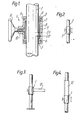
- Figures 2, 3 and 4 show some examples of embodiment of the invention according to Fig. 1.
- Fig. 2 illustrates the basic construction diagrammatically in the same way as Fig. 1.
- the locking device 1 is provided with a device 12 which may consist of a suspension device, a plate etc.
- the device 1 is used as a stopper or check piece for the upper movable tube 13.
- the lower ring 5 is replaced by a tube 5a which constitutes part of a stand.
- the locking device is in this case designated 1a and is otherwise shaped in the same way as according to Fig. 1.
- Fig. 6 differs from the embodiment according to Fig. 1 in that the two running rings are extended and form guide sleeves 4b and 5b.
- the locking device is designated 1b.
- the outer tube 3b is in this case part of a stand. Otherwise the device 1b is shaped in the same way as in preceding embodiments.
Landscapes
- Engineering & Computer Science (AREA)
- General Engineering & Computer Science (AREA)
- Mechanical Engineering (AREA)
- Mutual Connection Of Rods And Tubes (AREA)
- Vending Machines For Individual Products (AREA)
- Vehicle Body Suspensions (AREA)
- Axle Suspensions And Sidecars For Cycles (AREA)
Priority Applications (1)
| Application Number | Priority Date | Filing Date | Title |
|---|---|---|---|
| AT83103910T ATE28234T1 (de) | 1982-05-14 | 1983-04-21 | Blockiervorrichtung fuer zwei bauteile. |
Applications Claiming Priority (2)
| Application Number | Priority Date | Filing Date | Title |
|---|---|---|---|
| SE8203018 | 1982-05-14 | ||
| SE8203018A SE428243B (sv) | 1982-05-14 | 1982-05-14 | Anordning for lasning av tva element till varandra |
Publications (2)
| Publication Number | Publication Date |
|---|---|
| EP0094520A1 true EP0094520A1 (fr) | 1983-11-23 |
| EP0094520B1 EP0094520B1 (fr) | 1987-07-08 |
Family
ID=20346804
Family Applications (1)
| Application Number | Title | Priority Date | Filing Date |
|---|---|---|---|
| EP83103910A Expired EP0094520B1 (fr) | 1982-05-14 | 1983-04-21 | Dispositif pour le blocage de deux membres |
Country Status (5)
| Country | Link |
|---|---|
| EP (1) | EP0094520B1 (fr) |
| AT (1) | ATE28234T1 (fr) |
| DE (1) | DE3372398D1 (fr) |
| NO (1) | NO156221C (fr) |
| SE (1) | SE428243B (fr) |
Cited By (10)
| Publication number | Priority date | Publication date | Assignee | Title |
|---|---|---|---|---|
| GB2156421A (en) * | 1984-03-23 | 1985-10-09 | Blatchford & Sons Ltd | Clamping device |
| EP0167345A1 (fr) * | 1984-07-06 | 1986-01-08 | MICRA Ltd. | Dispositif à crampons |
| WO1986003562A1 (fr) * | 1984-12-03 | 1986-06-19 | Hoeiseth John | Dispositif de blocage |
| EP0199687A1 (fr) * | 1985-03-07 | 1986-10-29 | Verkstads AB Claes Johansson | Colonne de direction réglable pour véhicules |
| US5348415A (en) * | 1990-08-17 | 1994-09-20 | Ergonomiprodukter I Bodafors Ab | Locking device |
| DE29717668U1 (de) * | 1997-10-02 | 1997-11-20 | Fränzl, Robert, 84405 Dorfen | Fixierglied für die Herstellung einer Schraubverbindung |
| GB2389874A (en) * | 2002-04-22 | 2003-12-24 | Pentax Prec Co Ltd | Lock for operational ring of television camera lens for CCTV surveillance camera |
| US6698962B2 (en) * | 2002-02-13 | 2004-03-02 | Chi Yu Steel Co., Ltd. | Joint for a telescoping rod |
| EP1754893A3 (fr) * | 2005-08-16 | 2007-10-03 | Hans-Joachim Arning | Élément de serrage pour la fixation d'un élément en barre |
| WO2010029227A3 (fr) * | 2008-09-09 | 2010-06-10 | Laboratoires Protec | Manchon de fixation pour des montant d'une structure modulaire, notamment une structure télescopique escamotable, et structure comportant un tel manchon |
Families Citing this family (1)
| Publication number | Priority date | Publication date | Assignee | Title |
|---|---|---|---|---|
| SE503235C2 (sv) * | 1994-10-18 | 1996-04-22 | Mercado Medic Ab | Låsanordning för i stolar och bord ingående, rörliga delar |
Citations (3)
| Publication number | Priority date | Publication date | Assignee | Title |
|---|---|---|---|---|
| GB1309492A (en) * | 1970-05-01 | 1973-03-14 | Jonsson Aluminium Steel Eng Wo | Clamps for tubular articles |
| GB1435312A (en) * | 1973-04-06 | 1976-05-12 | Modern Aerials Ltd | Sectional or telescopic masts or struts |
| GB2077837A (en) * | 1980-06-10 | 1981-12-23 | Cambridge Store Syst Ltd | A pipe clamp and a method of making a pipe clamp |
Family Cites Families (4)
| Publication number | Priority date | Publication date | Assignee | Title |
|---|---|---|---|---|
| US3676770A (en) * | 1970-05-15 | 1972-07-11 | Anderson Power Products | Pulse sampling battery fuel gauging and resistance metering method and means |
| JPS5558739A (en) * | 1978-10-24 | 1980-05-01 | Nippon Denso Co | Method of and device for controlling voltage of automotive generator |
| DE2922910A1 (de) * | 1979-06-06 | 1980-12-11 | Rau Swf Autozubehoer | Anzeigevorrichtung fuer fahrzeuge |
| JPS56101151U (fr) * | 1979-12-29 | 1981-08-08 |
-
1982
- 1982-05-14 SE SE8203018A patent/SE428243B/sv not_active IP Right Cessation
-
1983
- 1983-04-21 EP EP83103910A patent/EP0094520B1/fr not_active Expired
- 1983-04-21 AT AT83103910T patent/ATE28234T1/de not_active IP Right Cessation
- 1983-04-21 DE DE8383103910T patent/DE3372398D1/de not_active Expired
- 1983-05-06 NO NO831608A patent/NO156221C/no not_active IP Right Cessation
Patent Citations (3)
| Publication number | Priority date | Publication date | Assignee | Title |
|---|---|---|---|---|
| GB1309492A (en) * | 1970-05-01 | 1973-03-14 | Jonsson Aluminium Steel Eng Wo | Clamps for tubular articles |
| GB1435312A (en) * | 1973-04-06 | 1976-05-12 | Modern Aerials Ltd | Sectional or telescopic masts or struts |
| GB2077837A (en) * | 1980-06-10 | 1981-12-23 | Cambridge Store Syst Ltd | A pipe clamp and a method of making a pipe clamp |
Cited By (11)
| Publication number | Priority date | Publication date | Assignee | Title |
|---|---|---|---|---|
| GB2156421A (en) * | 1984-03-23 | 1985-10-09 | Blatchford & Sons Ltd | Clamping device |
| EP0167345A1 (fr) * | 1984-07-06 | 1986-01-08 | MICRA Ltd. | Dispositif à crampons |
| WO1986003562A1 (fr) * | 1984-12-03 | 1986-06-19 | Hoeiseth John | Dispositif de blocage |
| EP0199687A1 (fr) * | 1985-03-07 | 1986-10-29 | Verkstads AB Claes Johansson | Colonne de direction réglable pour véhicules |
| US5348415A (en) * | 1990-08-17 | 1994-09-20 | Ergonomiprodukter I Bodafors Ab | Locking device |
| DE29717668U1 (de) * | 1997-10-02 | 1997-11-20 | Fränzl, Robert, 84405 Dorfen | Fixierglied für die Herstellung einer Schraubverbindung |
| US6698962B2 (en) * | 2002-02-13 | 2004-03-02 | Chi Yu Steel Co., Ltd. | Joint for a telescoping rod |
| GB2389874A (en) * | 2002-04-22 | 2003-12-24 | Pentax Prec Co Ltd | Lock for operational ring of television camera lens for CCTV surveillance camera |
| GB2389874B (en) * | 2002-04-22 | 2005-08-24 | Pentax Prec Co Ltd | Locking device for an operational ring of a television camera lens for a CCTV surveillance camera |
| EP1754893A3 (fr) * | 2005-08-16 | 2007-10-03 | Hans-Joachim Arning | Élément de serrage pour la fixation d'un élément en barre |
| WO2010029227A3 (fr) * | 2008-09-09 | 2010-06-10 | Laboratoires Protec | Manchon de fixation pour des montant d'une structure modulaire, notamment une structure télescopique escamotable, et structure comportant un tel manchon |
Also Published As
| Publication number | Publication date |
|---|---|
| ATE28234T1 (de) | 1987-07-15 |
| SE428243B (sv) | 1983-06-13 |
| NO156221C (no) | 1987-08-12 |
| NO156221B (no) | 1987-05-04 |
| DE3372398D1 (en) | 1987-08-13 |
| NO831608L (no) | 1983-11-15 |
| EP0094520B1 (fr) | 1987-07-08 |
Similar Documents
| Publication | Publication Date | Title |
|---|---|---|
| US5367852A (en) | Support system | |
| EP0094520A1 (fr) | Dispositif pour le blocage de deux membres | |
| EP0640197B1 (fr) | Systeme d'armature tubulaire | |
| US3069189A (en) | Pipe connector | |
| US8052352B2 (en) | Mine support having a linearly moveable and/or pivoting end plate | |
| EP0533376A1 (fr) | Supports ou dispositifs d'appui portatifs | |
| US4627149A (en) | Method of mounting an annular element on a metal tube of aluminum or an alloy thereof | |
| AU2004322231C1 (en) | Tables | |
| US5667328A (en) | Attachment member | |
| JPH0346685B2 (fr) | ||
| US11614199B2 (en) | Vertically adjustable pedestal for boat accessory | |
| EP0100333A1 (fr) | Jambe de force ou appui reglable | |
| US3868192A (en) | Method and means for assembling piston and piston rod | |
| US4547096A (en) | Alignment of tubular piles for joinder | |
| US7544008B2 (en) | Flange dressing and method for attaching a gas spring | |
| AU595612B2 (en) | Improvements in and relating to clamp members | |
| US6318926B1 (en) | Pivot bearing provided on support structures formed of shaped bars | |
| CA1057164A (fr) | Anneau de butee pour elements tubulaires telescopiques | |
| JPH0529597Y2 (fr) | ||
| US4735422A (en) | Precision chuck | |
| USRE25225E (en) | Shore attachment combination | |
| KR100522052B1 (ko) | 신속 체결 시스템 | |
| US3941494A (en) | Pipe clamp | |
| US20180222269A1 (en) | Wheel height adjustment assembly and methods of making and using same | |
| JPH0730624Y2 (ja) | タワークレーン支持水平ビームの長さ調整機構 |
Legal Events
| Date | Code | Title | Description |
|---|---|---|---|
| PUAI | Public reference made under article 153(3) epc to a published international application that has entered the european phase |
Free format text: ORIGINAL CODE: 0009012 |
|
| AK | Designated contracting states |
Designated state(s): AT BE CH DE FR GB IT LI LU NL SE |
|
| 17P | Request for examination filed |
Effective date: 19840320 |
|
| GRAA | (expected) grant |
Free format text: ORIGINAL CODE: 0009210 |
|
| AK | Designated contracting states |
Kind code of ref document: B1 Designated state(s): AT BE CH DE FR GB IT LI LU NL SE |
|
| PG25 | Lapsed in a contracting state [announced via postgrant information from national office to epo] |
Ref country code: NL Effective date: 19870708 Ref country code: LI Effective date: 19870708 Ref country code: IT Free format text: LAPSE BECAUSE OF FAILURE TO SUBMIT A TRANSLATION OF THE DESCRIPTION OR TO PAY THE FEE WITHIN THE PRESCRIBED TIME-LIMIT;WARNING: LAPSES OF ITALIAN PATENTS WITH EFFECTIVE DATE BEFORE 2007 MAY HAVE OCCURRED AT ANY TIME BEFORE 2007. THE CORRECT EFFECTIVE DATE MAY BE DIFFERENT FROM THE ONE RECORDED. Effective date: 19870708 Ref country code: FR Free format text: THE PATENT HAS BEEN ANNULLED BY A DECISION OF A NATIONAL AUTHORITY Effective date: 19870708 Ref country code: CH Effective date: 19870708 Ref country code: BE Effective date: 19870708 Ref country code: AT Effective date: 19870708 |
|
| REF | Corresponds to: |
Ref document number: 28234 Country of ref document: AT Date of ref document: 19870715 Kind code of ref document: T |
|
| PG25 | Lapsed in a contracting state [announced via postgrant information from national office to epo] |
Ref country code: SE Effective date: 19870731 |
|
| REF | Corresponds to: |
Ref document number: 3372398 Country of ref document: DE Date of ref document: 19870813 |
|
| REG | Reference to a national code |
Ref country code: CH Ref legal event code: PL |
|
| EN | Fr: translation not filed | ||
| NLV1 | Nl: lapsed or annulled due to failure to fulfill the requirements of art. 29p and 29m of the patents act | ||
| PG25 | Lapsed in a contracting state [announced via postgrant information from national office to epo] |
Ref country code: LU Free format text: LAPSE BECAUSE OF NON-PAYMENT OF DUE FEES Effective date: 19880430 |
|
| PLBE | No opposition filed within time limit |
Free format text: ORIGINAL CODE: 0009261 |
|
| STAA | Information on the status of an ep patent application or granted ep patent |
Free format text: STATUS: NO OPPOSITION FILED WITHIN TIME LIMIT |
|
| 26N | No opposition filed | ||
| PGFP | Annual fee paid to national office [announced via postgrant information from national office to epo] |
Ref country code: GB Payment date: 20010418 Year of fee payment: 19 Ref country code: DE Payment date: 20010418 Year of fee payment: 19 |
|
| REG | Reference to a national code |
Ref country code: GB Ref legal event code: IF02 |
|
| PG25 | Lapsed in a contracting state [announced via postgrant information from national office to epo] |
Ref country code: GB Free format text: LAPSE BECAUSE OF NON-PAYMENT OF DUE FEES Effective date: 20020421 |
|
| PG25 | Lapsed in a contracting state [announced via postgrant information from national office to epo] |
Ref country code: DE Free format text: LAPSE BECAUSE OF NON-PAYMENT OF DUE FEES Effective date: 20021101 |
|
| GBPC | Gb: european patent ceased through non-payment of renewal fee |
Effective date: 20020421 |