EP0167396A2 - Montage de sortie pour broyeur à billes - Google Patents
Montage de sortie pour broyeur à billes Download PDFInfo
- Publication number
- EP0167396A2 EP0167396A2 EP85304749A EP85304749A EP0167396A2 EP 0167396 A2 EP0167396 A2 EP 0167396A2 EP 85304749 A EP85304749 A EP 85304749A EP 85304749 A EP85304749 A EP 85304749A EP 0167396 A2 EP0167396 A2 EP 0167396A2
- Authority
- EP
- European Patent Office
- Prior art keywords
- vessel
- screen
- openings
- screen elements
- wall
- Prior art date
- Legal status (The legal status is an assumption and is not a legal conclusion. Google has not performed a legal analysis and makes no representation as to the accuracy of the status listed.)
- Withdrawn
Links
- 238000000227 grinding Methods 0.000 claims abstract description 27
- 239000007788 liquid Substances 0.000 claims description 19
- 238000004891 communication Methods 0.000 claims description 8
- 238000003801 milling Methods 0.000 claims description 7
- 239000002245 particle Substances 0.000 claims description 6
- 239000004576 sand Substances 0.000 abstract description 22
- 238000010276 construction Methods 0.000 abstract description 16
- 238000004140 cleaning Methods 0.000 abstract description 5
- 239000000047 product Substances 0.000 description 28
- 239000012530 fluid Substances 0.000 description 7
- 238000013459 approach Methods 0.000 description 6
- 238000001816 cooling Methods 0.000 description 5
- 238000013461 design Methods 0.000 description 4
- 239000000463 material Substances 0.000 description 4
- 230000013011 mating Effects 0.000 description 4
- 229920000642 polymer Polymers 0.000 description 4
- 230000000712 assembly Effects 0.000 description 3
- 238000000429 assembly Methods 0.000 description 3
- 239000002826 coolant Substances 0.000 description 3
- 239000012263 liquid product Substances 0.000 description 3
- 238000004519 manufacturing process Methods 0.000 description 3
- 230000000717 retained effect Effects 0.000 description 3
- 239000002002 slurry Substances 0.000 description 3
- 229910000831 Steel Inorganic materials 0.000 description 2
- 238000000576 coating method Methods 0.000 description 2
- 238000001914 filtration Methods 0.000 description 2
- 238000000034 method Methods 0.000 description 2
- 238000012545 processing Methods 0.000 description 2
- 239000010959 steel Substances 0.000 description 2
- 239000004699 Ultra-high molecular weight polyethylene Substances 0.000 description 1
- 238000005266 casting Methods 0.000 description 1
- 230000001276 controlling effect Effects 0.000 description 1
- 239000000498 cooling water Substances 0.000 description 1
- 230000008878 coupling Effects 0.000 description 1
- 238000010168 coupling process Methods 0.000 description 1
- 238000005859 coupling reaction Methods 0.000 description 1
- 238000005520 cutting process Methods 0.000 description 1
- 239000006185 dispersion Substances 0.000 description 1
- 238000005553 drilling Methods 0.000 description 1
- 239000000975 dye Substances 0.000 description 1
- 239000011521 glass Substances 0.000 description 1
- 239000000976 ink Substances 0.000 description 1
- 239000002917 insecticide Substances 0.000 description 1
- 230000002045 lasting effect Effects 0.000 description 1
- 230000005923 long-lasting effect Effects 0.000 description 1
- 239000003973 paint Substances 0.000 description 1
- 230000000737 periodic effect Effects 0.000 description 1
- 230000002093 peripheral effect Effects 0.000 description 1
- 239000002861 polymer material Substances 0.000 description 1
- 230000001105 regulatory effect Effects 0.000 description 1
- 238000005096 rolling process Methods 0.000 description 1
- 239000007787 solid Substances 0.000 description 1
- 229910001220 stainless steel Inorganic materials 0.000 description 1
- 239000010935 stainless steel Substances 0.000 description 1
- 239000000126 substance Substances 0.000 description 1
- 238000012546 transfer Methods 0.000 description 1
- 229920000785 ultra high molecular weight polyethylene Polymers 0.000 description 1
Images

Classifications
-
- B—PERFORMING OPERATIONS; TRANSPORTING
- B02—CRUSHING, PULVERISING, OR DISINTEGRATING; PREPARATORY TREATMENT OF GRAIN FOR MILLING
- B02C—CRUSHING, PULVERISING, OR DISINTEGRATING IN GENERAL; MILLING GRAIN
- B02C17/00—Disintegrating by tumbling mills, i.e. mills having a container charged with the material to be disintegrated with or without special disintegrating members such as pebbles or balls
- B02C17/16—Mills in which a fixed container houses stirring means tumbling the charge
- B02C17/161—Arrangements for separating milling media and ground material
Definitions
- This invention relates to an improved outlet structure for a liquid processing vessel of a small media mill, often referred to as a sand mill.
- the outlet structure includes an improved screen assembly and the related construction for mounting the screen assembly with respect to the sand mill vessel.
- Sand milling is a proven, practical, continuous, high production method of dispersing and milling particles in liquid to produce smooth, uniform, finely dispersed products.
- Some of the products in which the sand milling process is used includes paints, inks, dye stuffs, paper coatings, chemicals, magnetic tape coatings, insecticides, and other materials in which milling to a high degree of fineness is required.
- the material or slurry to be processed is introduced at one end of the processing chamber or vessel and pumped through a small diameter grinding media while a rotor within the vessel agitates the media to insure proper milling and dispersion of small particles in the liquid or slurry being processed.
- a rotor within the vessel agitates the media to insure proper milling and dispersion of small particles in the liquid or slurry being processed.
- the outlet structure typically includes a screen assembly which prevents the media from leaving the vessel while the processed liquid flows through the screen.
- U.S. Patent 4,441,658, issued April 10, 1984 describes a cup-shaped assembly that fits within a cylindrical wall leading to an outlet. The cup shape of the screen assembly provides a large filtering surface area.
- Other screen assemblies include segments forming a portion of a cylindrical wall. These screen components are typically formed of small diameter rods or strands which are welded at their intersections. A shortcoming of these welded constructions is that the screen become worn causing some of the strands of the screen break or the openings between the strands become large enough to allow passage of the grinding media..This requires early replacement of the screen.
- the screen together with the vessel outlet structure must also be arranged so as to provide easy disassembly and cleaning or replacement of the screen components.
- the screen and outlet construction be sufficiently versatile to be useful for both vertically oriented sand mills and horizontally oriented sand mills.
- a dump valve located at the lower end of the vessel.
- Prior horizontal mills are typically formed of sections which are bolted together and these sections must be disconnected. To access all of the media, usually results in media spilling out along the entire length of the vessel.
- This invention comprises an improved media mill having a vessel for containing the- product to be processed and for containing a small diameter grinding media.
- a rotor located in the vessel agitates the grinding media as the product to be processed is pumped or otherwise processed through the vessel.
- an improved screen and outlet construction To retain the media within the vessel while permitting the processed liquid to flow out of the vessel, there is provided an improved screen and outlet construction.
- This includes a cylindrical housing wall and a plurality of flat rings which are positioned within the cylindrical wall to form an annular stack.
- the cylindrical exterior of the stack is spaced inwardly from the surrounding cylindrical wall to define an annular passage.
- the screen elements form an interior cylindrical space.
- An end plate positioned on one end of the stack of screen elements closes one end of the cylindrical space.
- a plurality of the screen elements have openings which connect the annular passage surrounding the screen elements with the cylindrical space within the elements.
- the openings are formed by flat grooves or channels formed in an end face of the elements such that the face of the confronting or adjacent element cooperates - with the grooves to form a wall of the opening.
- These - openings include a dimension smaller than the grinding media so that the grinding media cannot pass into such openings, whereas the processed liquid can flow therethrough.
- the openings are substantially straight and direct through the screen elements so as to minimize any pressure drop across the openings.
- one end of the cylindrical wall includes an outlet through which the liquid product flows after it has passed through the screen assembly.
- the screen elements are clamped within the cylindrical housing so that the assembly can be readily disconnected and the screen elements replaced or cleaned.
- due to the radial thickness of the screen elements essentially eliminate the need for replacement from a wear standpoint.
- they may be readily replaced in the event a media of different size is to be used such that the openings through the screen element should be coordinated therewith.
- ribs extending inwardly from the cylindrical wall to position the screen elements spaced from the wall.
- lugs are provided which extend radially inwardly further than the ribs to be engaged by the end plate.
- a suitable clamp or retainer in the form of an annular member having a threaded exterior is threaded into one end of the cylindrical wall to clamp the screen elements and the end plate against the lugs.
- the stack of screen elements is positioned so that the cylindrical space within the elements is open to the liquid being processed in the vessel and to the grinding media, and the end plate of the construction is positioned close to but spaced from the outlet end wall.
- This outlet end wall may conveniently be formed integral with the cylindrical wall so that a cup-shaped housing is provided.
- the lugs positioning the end plate may likewise be formed integral with the cylindrical side wall and with the end wall. The lugs space the end plate from the end wall and thus-place the annular passage surrounding the screen elements in communication with the liquid outlet. With this arrangement, the liquid passes radially outwardly through the screen openings into the annular passage and thqp to the liquid outlet, while the grinding media is retained within the vessel and the cylindrical space within the screen assembly.
- the cup-shaped housing may conveniently be formed with an outwardly-extending flange which mates with a flange on the sand mill vessel such that the screen outlet housing may be quickly connected or disconnected to the vessel flange by means of a quick/disconnect clamp ring.
- the screen assembly essentially forms an extension of the sand mill vessel with the rotor within the vessel extending into the screen assembly.
- the rugged construction of the screen assembly is such that it can withstand the abrasive action of the grinding media directly adjacent to the moving rotor.
- the wearing of the interior wall of the screen elements caused by the abrasive grinding media does not increase the screen size of the openings through the screen assembly, so that media continues to be prevented from passing into such openings.
- the" outlet is typically oriented transversely with respect to the axis of the vessel.
- An opening in the exterior wall of the vessel near its upper end may however be provided with a suitable flange for mating with the flange of a screen outlet housing of the type discussed above in connection with the horizontal sand mill.
- the flow through the screen elements may be reversed.
- a cylindrical outlet housing wall is preferably formed integral with the upper portion of the vessel, with the cylindrical outlet wall extending generally transverse to the axis of the vessel. The screen assembly stack is reversed so that the end plate is located at the end closest to the vessel rotor.
- the lugs for positioning the end plate extend inwardly from the cylindrical housing wall adjacent the vessel and the positioning ribs are still formed integral with the side wall of the cylindrical housing so that the annular passage surrounding the screen elements is in direct communication with the vessel.
- the opposite end of the stack of screen elements is open to an outlet in a cover secured to the outer end of the cylindrical housing. Consequently, the product flow through the screen is into the annular passage and then radially inwardly through the screen openings into the cylindrical space within the elements and then directly through an outlet in the end cover.
- the screen elements are compressed or held against the end plate and the positioning lugs by an annular member which threads into the outer end of the cylindrical wall, adjacent the cover.
- the openings formed in the screen elements are preferably made by a cutting or grinding operation directly across one face of the annular element so that a pair of grooves channels are formed on the face of the element diametrically opposite from each other. A second cut 90° from the first is then made across the face of the element to form a second pair of wide diametrically space ⁇ grooves.
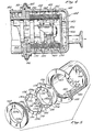
- FIG. 3 Shown in Figure 3 is a horizontal media mill comprising a mill motor 10 which has a shaft 12 which rotates a rotor 16.
- the shaft 12 which drives the rotor 16 extends cantilevered directly from the mill motor 10.
- the portion 14 of the shaft 12 on which the rotor 16 is slideably mounted is preferably square in transverse cross section to mate with a similar opening in the rotor to prevent rotational slippage of the rotor 16.
- the shaft portion 14 and the rotor may be any symmetrical shape which has a straight portion to prevent slippage, or the rotor 16 may be keyed to the shaft 12.
- the rotor 16 extends through a cylindrical vessel 18, in which media 20 and product are agitated by the rotor 16. Product is introduced to the vessel through product inlet 19 at the motor end of the vessel.
- the rotor 16 is preferably fabricated from a wear resistant polymer, and is machined from a solid bar of the polymer.
- a wear resistant polymer which is abrasively tougher than steel is an ultra high molecular weight polyethylene.
- the fabrication process consists of drilling a pilot hole axially through the center of the bar, and then broaching a square hole through the center of the bar, surrounding the pilot hole.
- fabrication may begin with a tube of the polymer so that the first step is broaching the square cross section in the center hole of the tube.
- the piece is turned on a lathe to be trimmed into - a cylinder of a desired outside diameter.
- each disc 24 is undercut on both axial faces to create annular grooves 26 in the area where the discs 24 join the cylindrical portion 22.
- the rotor is slideably mounted on the square portion 14 of the shaft 12, and is simply secured in place by a nut 28 screwed on a threaded portion 30 on the end of the shaft 12.
- the nut 28 is of sufficient diameter to abut the end of the rotor, so that it does not slide off the shaft.
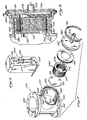
- the shaft and rotor protrude through the open end of the vessel 18, which is enclosed by a screen assembly 32.
- the open end of the vessel is opposite the end of the vessel adjacent the product inlet 19.
- the screen assembly 32 is cup-shaped, and includes a tubular screen unit 34, a circular end plate 36, and an annular flange 38 on the open opposite end.
- the milled product can pass through the screen unit 34 while the media is retained in the vessel.
- the screen assembly 32 is aligned and temporarily supported -on the vessel assembly 40 by means of a plurality of dowel pins 47 positioned in the screen flange 38 and a large annular flange 48 secured to the vessel and a surrounding cylindrical outer shell 58.
- a cup-shaped end cover assembly 44 encloses the screen assembly 32 and is mounted to the vessel assembly 40 with a retainer ring 46 which surrounds and clamps together with a flange 55 on the cover assembly which mates with flange 48 of the vessel assembly.
- the end cover assembly is also retained in engagement with the vessel assembly flange 48 by dowel pins 51 in mating holes in the flanges 48 and 55.
- the cover flange 55 includes a shoulder 42 which more positively holds the screen flange 38 in engagement with the vessel flange 48.
- the retainer ring 46 consists of a circular ring which is split in at least one place to enable expansion, and which is fastened together at those splits by a quickly releasable fastening means, not shown.
- the retainer ring 46 is fastened by a clamp of the general type shown in the above-referenced U.S. Patent No. 4,140,283.
- the end cover assembly 40 includes a pair of . diametrically spaced, upper and lower product outlets 49, through which the milled product filtering through the screen element 34 can flow.
- the screen unit forms a tubular portion of the screen assembly, and is bolted at one end to the screen flange 38 and at the other end to the circular end plate 36.
- the screen unit comprises a plurality of rings or annular discs 35, each having a central opening and a pair of opposed faces.
- the discs are stacked with the central openings aligned to form a tube or cylinder having a central axial space. This space surrounds a portion of the rotor which protrudes through the vessel.
- the opposed faces form a plurality of radial openings in the cylinder between adjacent discs to allow the passage of processed liquid from the vessel, or central axial opening, to the outside of the cylinder.
- the smallest dimension of each radial passage is small enough to prevent flow of the grinding media through the passage, so only liquid product leaves the vessel.
- the vessel assembly is also removably mounted at its inlet end to a housing assembly 50 which is bolted to the mill motor 10 at one end and is coupled to the vessel assembly at the other end, encasing the shaft 12 throughout its length.
- Quickly removable retainer ring 46 clamps the radially extending flange 57 of the vessel assembly to the flange-59 of the housing assembly 50.
- the mill further includes an integrated hydraulic system having a single electric motor 72 which drives a circulating pump 74; the working fluid pressurized by. that circulating pump being utilized to cool the vessel, provide pressure to a seal 52, drive a hydraulic motor 75 which rotates a product pump 76, and hydraulically tilt the mill when it is to be cleaned.
- the motor 72, circulating pump 74, motor 75, and product pump 76 are located within the base 66, as schematically shown in Figure 1.
- the vessel is sealed from the exterior by the pressure seal 52 which is a cartridge that is bolted to the housing assembly 50 and surrounds the shaft 12. Pressurized working fluid is pumped into the seal 52 through a seal inlet 53 to provide a pressure greater than that on the vessel side of the seal and thus prevent leakage out of the vessel. This enables the product to be pumped through the vessel at a desired pressure and flow rate.
- Pressurized fluid also acts as a coolant for the vessel by being circulated through a cooling jacket inlet 54 and into the cooling jacket 56 defined by the outer wall of the vessel 18 and the surrounding cylindrical outer shell 58.
- the vessel has a plurality of fins 60 protruding radially into the cooling jacket 56 to facilitate the transfer of friction generated heat within the vessel to the coolant.
- a cooling jacket outlet through which the coolant is returned to a heat exchanger 78 where it is circulated and cooled itself by cooling water, before being returned to a reservoir 77.
- the pressurized working fluid from the pump 74 is also used to power a hydraulic motor 75 driving a product pump 76, which pumps the product through the vessel, thus eliminating the need for a separate electric product pump motor and associated explosion-proof switch.
- the fluid also powers the hydraulic ram 62 shown in Figure 2, which extends to tilt the mill about a trunion .64, facilitating the cleaning of the vessel.
- a horizontal mill having a cantilevered shaft, as shown, is particularly suited for this tilting application.
- Figure 1 shows the mill in its normal horizontal operating state
- Figure 2 shows the mill in its tilted position.
- Two mounts 80 extend from the superstructure 82, on either side of the housing assembly 50.
- the trunions 64 are fixed to and protrude radially outward from the sides of the housing assembly, and pivotably rest within circular holes in the mounts 80.
- the hydraulic ram 62 is located within the superstructure 82, and is pivotably secured to .
- the base 66 at one end, and is pivotably secured to a motor mounting plate 68 at the other end.
- the motor mounting plate 68 is fastened to the mill motor 10.
- Both the electric motor powering the hydraulic system and the electric mill motor are regulated by a pneumatic control system (not shown), which runs on compressed shop air.
- a suitable control panel 84 for controlling the operation of the system is conveniently supported on the superstructure 82.
- the pneumatic system saves the expense of explosion-proof electrical switches which must be used when a flammable product is being milled.
- a liquid product or slurry is pumped by the hydraulically driven product pump 76 through the product inlet 19 to the vessel 18 and is dispersed throughout the grinding media 20 by the rotating rotor 16.
- a single speed, 3600 rpm electric mill motor turns 2-3/4 inch diameter rotor discs 24 at a rim speed of 2590 ft./min.
- the milled product filters through the screen unit 34 to the product outlet 49.
- the vessel is being cooled by the working fluid which is circulating through the cooling jacket 56.
- the working fluid provides pressure to the seal 52 surrounding the shaft 12 where it enters the vessel.
- the mill When the vessel is to be cleaned, the mill is tilted about the trunion 64 by the extension of the hydraulic ram 62, lowering the outlet end of the vessel.
- the end cover assembly and screen mounting assembly are then quickly removed from the vessel assembly by first unfastening the retainer ring.
- the pins 47 and 51 prevent the end cover and screen assemblies from both instantly falling off.
- an axial pull on the end cover, and then the screen assembly will dislodge the pins from their corresponding holes.
- the angle of the mill allows the media to conveniently drain out the then open end of the vessel, and into a suitable container 70. With the . end cover and the screen assembly uncoupled, .the rotor is .
- the grinding media is usually added through the product inlet 19, but it may also be added through the open end of the vessel when its screen is removed.
- the ram 62 may be useful in tilting the vessel to distribute media.
- the unit may be designed to lower the motor end of the vessel slightly, if desired.
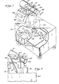
- FIG. 4 illustrates a much preferred construction.
- This includes a cup-shaped end cover assembly or outlet construction 144, having a housing 143 with a cylindrical wall 145 and an integral end wall 147.
- An outwardly-extending flange 155 is formed on the open end of the cylindrical wall and mates with a large annular flange 48 formed on the open end of the sand mill vessel 18.
- a cylindrical or tubular screen 134 is formed by a plurality of ring-shaped elements or disks 135 positioned within the cylindrical wall 145.
- these screen elements 135 are positioned or spaced inwardly from the cylindrical wall 145 by three ribs 160 which extend radially inwardly and extend axially throughout the length of the stack of screen elements 135.
- the ribs 160 are formed integral with the wall 145 such that the entire cup-shaped housing may be cast and the ribs than machined on their inner edge to provide the desired diameter for positioning the screen elements in alignment.
- the ribs 160 space the screen elements 135 from the cylindrical 145 so as to form an annular passage 162 interrupted only by the ribs.
- a closed end plate 136 is located on the downstream end of the stack of screen elements, being radially positioned by the ribs 160.
- the end plate is further confined by three lugs 164 which form axial extensions of ribs 160 but extend radially inwardly further than the ribs to provide surfaces that engage the outer axial face of the end plate 136 at three circumferentially spaced locations, as may be visualized from Figures 4 and 5.
- the lugs 164 space the end plate 136 from the housing end wall 147 so as to form a disk shaped space 166 which is in communication with the annular space 162 through arcuate windows between the lugs 164.
- the stack formed by the screen elements and the end plate 136 is axially pressed or held against the lugs 164 by means of a ring-shaped member forming a clamp or threaded fastener 168.
- the member 168 has an internal diameter equal to the internal diameter of the screen elements and the vessel.
- the external diameter of the member 168 is threaded to thread into mating threads formed on the interior cylindrical wall 145 adjacent the open end of the housing, radially aligned with the flange 155.
- the fastener member 168 is readily rotatable by use of a pair of sockets 168a formed on the outer face as shown in Figure 5.
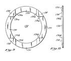
- a plurality of openings 170 are formed between each adjacent- pair of screen elements 135 connecting the cylindrical interior space 172 within the screen assembly with the annular passage 162 surrounding the screen elements.
- the openings 170 are in the form of shallow cuts or grooves made in one axial face of each screen element. Preferably four grooves are made in each element, with such grooves having side walls 170a and b which are parallel to each other. That is, they are non-radial. With such an arrangement, the cross-section of each opening 170 is constant.
- the axial depth of each cut or opening is very small. It is sized to prevent grinding media from moving into the opening.
- the circumferential or lateral dimension of a slot is not critical, although it is preferable that they be as wide as possible, consistent with other design requirements. This is important since the combined area of the screen openings should be greater than the inlet area to the mill so that the screen does not produce a restriction.
- any broken or worn media particles that should enter a screen opening 170 are not trapped in the screen openings, and thus do not cause clogging of the screen.
- the purpose of the screen is to keep media in the mill, and not to capture particles in the screen passages.
- the opening 70 may be formed by cuts which are machined into the face of the screen element by relative movement of a mill cutter and the element directly across the element. A similar cut can then be made 90° with respect to the first cut to form the other pair of diametrically spaced openings.
- These pads 174 receive the axial load when the screen elements 135 are clamped within the housing by the threaded fastener 168.
- the pads 174 are preferable placed into axial alignment; however, it should be noted that the screen elements are sufficiently rugged that alignment is not critical.
- the screen elements may be quickly installed and positioned by the ribs 160 without critical concern for angular orientation.
- the screen elements may be made of varying thickenesses, as strength and other design requirements dictate. Likewise, the screen elements may be made of any desired material, such as stainless steel or an abrasive- resistant polymer material.
- the axial depth of the slots or openings 170 is, of course, to be consistent with the size of the media to be utilized in the mill. Further, as mentioned above, screen elements of different slot depths may be utilized for different media size, and the screen assembly design is such that a stack of elements may be quickly and conveniently replaced by a different stack as needed. Of course, the removed stack can be reused at a later time if the media is to be changed again.
- FIG. 6 there is substantially illustrated a vertical sand mill 200 having a vertically oriented vessel 202 with a product inlet 204 at the lower end and a product outlet 206 near the upper end.
- a rotor (not shown) is vertically mounted in the vessel with the rotor shaft extending upwardly out of the upper end of the vessel through a tubular sleeve 108.
- a rotor similar to that shown in the arrangement of Figure 3, or any well-known prior art rotor, may be utilized.
- the upper end of the vessel and an outlet structure for the vessel includes a generally T-shaped casting 210 having a vertically oriented cylindrical portion 212 which forms a part of the vessel 202 and a generally horizontal portion forming an outlet housing 245.
- the vertical portion 212 includes upper and lower flanges 214 and 216 for convenient connection to the remainder of the vessel.
- the interior cylindrical wall 245 is formed with three axially extending ribs 260.
- three lugs 264 which are axially aligned with the ribs but extend radially inwardly further to form axial support surfaces for an end plate 136 and a plurality of screen elements 135 that form a screen assembly 234.
- the end plate and the stack of screen elements are clamped or held against the lugs by means of an externally threaded annular fastener 168 which threads into mating threads formed in the open outer end of the housing 245.
- a cover plate 280 closes the outer open end of the screen assembly 234 and an outer peripheral flange 281 of the cover plate mates with a similar flange 255 formed on the open outer end of the cylindrical wall 245. These flanges are held in place by a suitable quick connect/disconnect clamp arrangement 46 as described above.
- the ribs 260 space the screen elements 135 radially inwardly from the outer cylindrical wall 245 creating an annular passage 262 which is in direct communication with the sand mill vessel.
- the product can flow axially into this passage, radially inwardly, as indicated by the arrows 284 shown in Figure 8, through the openings 170 into the cylindrical space 272, and then flows axially through an outlet 206 in the cover plate.
- the entire housing surrounding the screen elements is not removable, the screen elements may nevertheless be easily removed or installed by simply removing the quick disconnect coupling, unthreading the: fastener 168 and removing the screen elements as well as the end plate, as desired.
- a flange could be positioned at the vessel end of the housing so that an arrangement essentially like that shown in Figure 4 could be employed in the vertically oriented housing as well.
Landscapes
- Engineering & Computer Science (AREA)
- Food Science & Technology (AREA)
- Crushing And Grinding (AREA)
Applications Claiming Priority (4)
| Application Number | Priority Date | Filing Date | Title |
|---|---|---|---|
| US62791884A | 1984-07-05 | 1984-07-05 | |
| US627918 | 1984-07-05 | ||
| US06/746,440 US4624418A (en) | 1984-10-19 | 1985-06-21 | Media mill outlet assembly |
| US746440 | 1985-06-21 |
Publications (2)
| Publication Number | Publication Date |
|---|---|
| EP0167396A2 true EP0167396A2 (fr) | 1986-01-08 |
| EP0167396A3 EP0167396A3 (fr) | 1987-11-04 |
Family
ID=27090561
Family Applications (1)
| Application Number | Title | Priority Date | Filing Date |
|---|---|---|---|
| EP85304749A Withdrawn EP0167396A3 (fr) | 1984-07-05 | 1985-07-03 | Montage de sortie pour broyeur à billes |
Country Status (1)
| Country | Link |
|---|---|
| EP (1) | EP0167396A3 (fr) |
Cited By (1)
| Publication number | Priority date | Publication date | Assignee | Title |
|---|---|---|---|---|
| EP0178760A3 (fr) * | 1984-10-19 | 1987-11-19 | Morehouse Industries, Inc. | Broyeur horizontal comportant des éléments de broyage |
Family Cites Families (3)
| Publication number | Priority date | Publication date | Assignee | Title |
|---|---|---|---|---|
| US4140283A (en) * | 1977-11-14 | 1979-02-20 | Morehouse Industries, Inc. | Sandmill vessel with inlet diffuser and removeable outlet filter |
| US4267045A (en) * | 1978-10-26 | 1981-05-12 | The Babcock & Wilcox Company | Labyrinth disk stack having disks with integral filter screens |
| US4441658A (en) * | 1981-11-16 | 1984-04-10 | Morehouse Industries, Inc. | Sandmill screen mounting assembly |
-
1985
- 1985-07-03 EP EP85304749A patent/EP0167396A3/fr not_active Withdrawn
Cited By (1)
| Publication number | Priority date | Publication date | Assignee | Title |
|---|---|---|---|---|
| EP0178760A3 (fr) * | 1984-10-19 | 1987-11-19 | Morehouse Industries, Inc. | Broyeur horizontal comportant des éléments de broyage |
Also Published As
| Publication number | Publication date |
|---|---|
| EP0167396A3 (fr) | 1987-11-04 |
Similar Documents
| Publication | Publication Date | Title |
|---|---|---|
| US4651935A (en) | Horizontal media mill | |
| US4624418A (en) | Media mill outlet assembly | |
| US3844490A (en) | Apparatus for dispersing finely divided solid particles in a liquid vehicle | |
| KR950012297B1 (ko) | 입자상 재료 처리장치 | |
| JPH0760147A (ja) | 撹拌粉砕装置 | |
| CA2122416C (fr) | Appareil de meulage a l'eau et methodes connexes | |
| KR100321859B1 (ko) | 분쇄기 | |
| US20030013592A1 (en) | Centrifuge with clutch mechanism for synchronous blade and bowl rotation | |
| CA1130794A (fr) | Broyeur a sable avec diffuseur d'entree et filtre de sortie amovible | |
| KR20050058514A (ko) | 교반장치가 제공된 볼 밀 장치 | |
| US4742966A (en) | Media mill screen assembly | |
| JPH0669538B2 (ja) | 予め液体内に分散させた固体を粉砕および細砕するためのミル | |
| US4709863A (en) | Media mill screen assembly | |
| CA1091210A (fr) | Appareil pour disperser des particules solides finement divisees, dans un vehicule liquide | |
| EP0167396A2 (fr) | Montage de sortie pour broyeur à billes | |
| US4582266A (en) | Centrifugal media mill | |
| US4441658A (en) | Sandmill screen mounting assembly | |
| JPH10230182A (ja) | 粉砕機 | |
| JPS6125647A (ja) | 粉砕装置 | |
| US20090212141A1 (en) | Milling apparatus | |
| JP4373179B2 (ja) | 粉砕機 | |
| US4746069A (en) | Centrifugal media mill | |
| KR20100005419U (ko) | 액상 원료 교반기의 교반 매체 스크린 장치 | |
| US5114080A (en) | Grinding body separator in mills for triturating and breaking up solids predispersed in liquids | |
| JP2005199125A (ja) | メディア攪拌ミル |
Legal Events
| Date | Code | Title | Description |
|---|---|---|---|
| PUAI | Public reference made under article 153(3) epc to a published international application that has entered the european phase |
Free format text: ORIGINAL CODE: 0009012 |
|
| AK | Designated contracting states |
Designated state(s): BE DE FR GB |
|
| PUAL | Search report despatched |
Free format text: ORIGINAL CODE: 0009013 |
|
| AK | Designated contracting states |
Kind code of ref document: A3 Designated state(s): BE DE FR GB |
|
| STAA | Information on the status of an ep patent application or granted ep patent |
Free format text: STATUS: THE APPLICATION IS DEEMED TO BE WITHDRAWN |
|
| 18D | Application deemed to be withdrawn |
Effective date: 19880505 |
|
| RIN1 | Information on inventor provided before grant (corrected) |
Inventor name: SZKARADEK, EDWARD J. |