EP0167416B1 - Verfahren zur Herstellung einer zellförmigen Struktur zum Bedecken einer gekrümmten Oberfläche - Google Patents
Verfahren zur Herstellung einer zellförmigen Struktur zum Bedecken einer gekrümmten Oberfläche Download PDFInfo
- Publication number
- EP0167416B1 EP0167416B1 EP85400840A EP85400840A EP0167416B1 EP 0167416 B1 EP0167416 B1 EP 0167416B1 EP 85400840 A EP85400840 A EP 85400840A EP 85400840 A EP85400840 A EP 85400840A EP 0167416 B1 EP0167416 B1 EP 0167416B1
- Authority
- EP
- European Patent Office
- Prior art keywords
- strip
- parallel
- points
- plane
- cylinder
- Prior art date
- Legal status (The legal status is an assumption and is not a legal conclusion. Google has not performed a legal analysis and makes no representation as to the accuracy of the status listed.)
- Expired - Lifetime
Links
- 238000004519 manufacturing process Methods 0.000 title claims description 5
- 210000003850 cellular structure Anatomy 0.000 title claims 3
- 238000000034 method Methods 0.000 claims description 10
- 238000005304 joining Methods 0.000 claims description 7
- 210000004027 cell Anatomy 0.000 claims 4
- 241000264877 Hippospongia communis Species 0.000 description 20
- 239000000047 product Substances 0.000 description 13
- 230000001413 cellular effect Effects 0.000 description 8
- 230000006835 compression Effects 0.000 description 3
- 238000007906 compression Methods 0.000 description 3
- 239000003292 glue Substances 0.000 description 3
- 238000013519 translation Methods 0.000 description 3
- 230000001186 cumulative effect Effects 0.000 description 2
- 239000000463 material Substances 0.000 description 2
- 241000237509 Patinopecten sp. Species 0.000 description 1
- 230000000712 assembly Effects 0.000 description 1
- 238000000429 assembly Methods 0.000 description 1
- 238000005219 brazing Methods 0.000 description 1
- 230000005465 channeling Effects 0.000 description 1
- 239000011162 core material Substances 0.000 description 1
- 238000005260 corrosion Methods 0.000 description 1
- 230000007797 corrosion Effects 0.000 description 1
- 238000013461 design Methods 0.000 description 1
- 230000001627 detrimental effect Effects 0.000 description 1
- 238000011161 development Methods 0.000 description 1
- 238000010586 diagram Methods 0.000 description 1
- 239000012467 final product Substances 0.000 description 1
- 239000012530 fluid Substances 0.000 description 1
- 239000000295 fuel oil Substances 0.000 description 1
- 230000005484 gravity Effects 0.000 description 1
- 238000009434 installation Methods 0.000 description 1
- 238000009413 insulation Methods 0.000 description 1
- 239000012774 insulation material Substances 0.000 description 1
- 239000012212 insulator Substances 0.000 description 1
- 239000003949 liquefied natural gas Substances 0.000 description 1
- 238000003754 machining Methods 0.000 description 1
- 238000012986 modification Methods 0.000 description 1
- 230000004048 modification Effects 0.000 description 1
- 239000003209 petroleum derivative Substances 0.000 description 1
- 239000000700 radioactive tracer Substances 0.000 description 1
- 235000020637 scallop Nutrition 0.000 description 1
- 238000003466 welding Methods 0.000 description 1
Images





Classifications
-
- B—PERFORMING OPERATIONS; TRANSPORTING
- B32—LAYERED PRODUCTS
- B32B—LAYERED PRODUCTS, i.e. PRODUCTS BUILT-UP OF STRATA OF FLAT OR NON-FLAT, e.g. CELLULAR OR HONEYCOMB, FORM
- B32B3/00—Layered products comprising a layer with external or internal discontinuities or unevennesses, or a layer of non-planar shape; Layered products comprising a layer having particular features of form
- B32B3/10—Layered products comprising a layer with external or internal discontinuities or unevennesses, or a layer of non-planar shape; Layered products comprising a layer having particular features of form characterised by a discontinuous layer, i.e. formed of separate pieces of material
- B32B3/12—Layered products comprising a layer with external or internal discontinuities or unevennesses, or a layer of non-planar shape; Layered products comprising a layer having particular features of form characterised by a discontinuous layer, i.e. formed of separate pieces of material characterised by a layer of regularly- arranged cells, e.g. a honeycomb structure
-
- B—PERFORMING OPERATIONS; TRANSPORTING
- B29—WORKING OF PLASTICS; WORKING OF SUBSTANCES IN A PLASTIC STATE IN GENERAL
- B29D—PRODUCING PARTICULAR ARTICLES FROM PLASTICS OR FROM SUBSTANCES IN A PLASTIC STATE
- B29D24/00—Producing articles with hollow walls
- B29D24/002—Producing articles with hollow walls formed with structures, e.g. cores placed between two plates or sheets, e.g. partially filled
- B29D24/005—Producing articles with hollow walls formed with structures, e.g. cores placed between two plates or sheets, e.g. partially filled the structure having joined ribs, e.g. honeycomb
-
- B—PERFORMING OPERATIONS; TRANSPORTING
- B32—LAYERED PRODUCTS
- B32B—LAYERED PRODUCTS, i.e. PRODUCTS BUILT-UP OF STRATA OF FLAT OR NON-FLAT, e.g. CELLULAR OR HONEYCOMB, FORM
- B32B1/00—Layered products having a non-planar shape
-
- D—TEXTILES; PAPER
- D21—PAPER-MAKING; PRODUCTION OF CELLULOSE
- D21F—PAPER-MAKING MACHINES; METHODS OF PRODUCING PAPER THEREON
- D21F1/00—Wet end of machines for making continuous webs of paper
- D21F1/60—Cylinder moulds
-
- F—MECHANICAL ENGINEERING; LIGHTING; HEATING; WEAPONS; BLASTING
- F16—ENGINEERING ELEMENTS AND UNITS; GENERAL MEASURES FOR PRODUCING AND MAINTAINING EFFECTIVE FUNCTIONING OF MACHINES OR INSTALLATIONS; THERMAL INSULATION IN GENERAL
- F16L—PIPES; JOINTS OR FITTINGS FOR PIPES; SUPPORTS FOR PIPES, CABLES OR PROTECTIVE TUBING; MEANS FOR THERMAL INSULATION IN GENERAL
- F16L59/00—Thermal insulation in general
- F16L59/14—Arrangements for the insulation of pipes or pipe systems
-
- Y—GENERAL TAGGING OF NEW TECHNOLOGICAL DEVELOPMENTS; GENERAL TAGGING OF CROSS-SECTIONAL TECHNOLOGIES SPANNING OVER SEVERAL SECTIONS OF THE IPC; TECHNICAL SUBJECTS COVERED BY FORMER USPC CROSS-REFERENCE ART COLLECTIONS [XRACs] AND DIGESTS
- Y10—TECHNICAL SUBJECTS COVERED BY FORMER USPC
- Y10T—TECHNICAL SUBJECTS COVERED BY FORMER US CLASSIFICATION
- Y10T428/00—Stock material or miscellaneous articles
- Y10T428/13—Hollow or container type article [e.g., tube, vase, etc.]
-
- Y—GENERAL TAGGING OF NEW TECHNOLOGICAL DEVELOPMENTS; GENERAL TAGGING OF CROSS-SECTIONAL TECHNOLOGIES SPANNING OVER SEVERAL SECTIONS OF THE IPC; TECHNICAL SUBJECTS COVERED BY FORMER USPC CROSS-REFERENCE ART COLLECTIONS [XRACs] AND DIGESTS
- Y10—TECHNICAL SUBJECTS COVERED BY FORMER USPC
- Y10T—TECHNICAL SUBJECTS COVERED BY FORMER US CLASSIFICATION
- Y10T428/00—Stock material or miscellaneous articles
- Y10T428/24—Structurally defined web or sheet [e.g., overall dimension, etc.]
- Y10T428/24149—Honeycomb-like
-
- Y—GENERAL TAGGING OF NEW TECHNOLOGICAL DEVELOPMENTS; GENERAL TAGGING OF CROSS-SECTIONAL TECHNOLOGIES SPANNING OVER SEVERAL SECTIONS OF THE IPC; TECHNICAL SUBJECTS COVERED BY FORMER USPC CROSS-REFERENCE ART COLLECTIONS [XRACs] AND DIGESTS
- Y10—TECHNICAL SUBJECTS COVERED BY FORMER USPC
- Y10T—TECHNICAL SUBJECTS COVERED BY FORMER US CLASSIFICATION
- Y10T428/00—Stock material or miscellaneous articles
- Y10T428/24—Structurally defined web or sheet [e.g., overall dimension, etc.]
- Y10T428/24149—Honeycomb-like
- Y10T428/24165—Hexagonally shaped cavities
Definitions
- the present invention relates to a method for producing a honeycomb structure, in particular intended to cover a cylinder or more generally a left surface.
- honeycombs planar honeycomb bodies
- honeycombs planar honeycomb bodies
- sheets or rectilinear strips which are partially glued to one another along transverse zones all having transverse sides parallel to each other, the obtaining the final product by pulling, perpendicular to the plane of the sheets or strips, to obtain prismatic cells with a more or less regular hexagonal shape.
- the cells obtained have walls whose sides, determined by the assembly lines, are all mutually parallel.
- Such a product can only be placed on a cylinder if the ratio of its thickness to the diameter of this cylinder is very small. As soon as this ratio rises, significant stresses appear in the walls which can either buckle in the compression zone or tear in the traction zone.
- the process according to the invention avoids these drawbacks and makes it possible to produce very thick structures which can arise naturally, with very low forces and constraints limited to those of expansion, in the case where the body is manufactured in the 'compressed state, on cylindrical walls whose local radius of curvature may be small.
- the honeycomb structure obtained according to the present invention is in particular intended to cover at least partially a cylindrical surface, it comprises cells delimited by several walls, at least one cell comprising at least one wall having at least two edges substantially parallel to each other and at least one wall comprising at least two edges not parallel to each other, each of these edges substantially parallel and not parallel to each other, having an orthogonal projection of non-zero length on a normal to said cylindrical surface passing through the edge considered.
- honeycomb structure according to the invention is obtained from curved strips, that is to say that the strip or strips comprises at least one non-rectilinear part.
- a structure comprising several cells, obtained according to the invention can be produced from at least one curved strip comprising several zones arranged transversely with respect to this strip, some of them corresponding to walls having substantially parallel edges and certain others corresponding to walls having non-parallel edges.
- zones may be assembly zones, each of which is intended to be secured to another assembly zone, while others may be free zones not used for assembly, but connecting the zones d 'assembly.
- At least some of the assembly zones may correspond to walls having substantially parallel edges.
- At least some of said free zones may correspond to walls having substantially parallel edges.
- a cell comprising at least one wall having two edges substantially parallels defining a first plane and at least one wall having two non-parallel coplanar edges defining a second plane can advantageously be arranged on the surface to be covered in such a way that the angle defined by the first plane with the direction defined by one of the generatrices of the cylinder is less than the angle defined by the second plane with this same direction.
- the structure obtained according to the invention may comprise one or more bands, possibly substantially helical.
- the structure obtained according to the invention may comprise several bands, each of these bands closing in on itself.
- the honeycomb structure may include cells having an intermediate shape between that of a prism trunk and that of a pyramid trunk.
- the base of this cell can be substantially hexagonal and possibly constitute a regular hexagon.
- honeycomb structure is intended to cover at least partially an area defined by a cylinder of revolution.
- the honeycomb structure obtained according to the invention may comprise at least one wall belonging to a plane substantially perpendicular to the direction of the generator of the cylinder to be covered at least partially.
- the honeycomb structure obtained according to the invention may comprise at least one wall belonging to a plane substantially parallel to the direction of a generator of the cylinder to be covered at least partially.
- Said transverse straight line can pass substantially in the vicinity of the point situated in the middle of the rectilinear or curvilinear segment defined by the reference line joining the two points of said pair.
- portion of the cylinder to be lined can be covered with the honeycomb structure according to the invention both on its convex face and on its concave face.
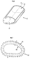
- FIG. 1 represents a cylinder 37.
- This cylinder has a straight section 38.
- the axis 39 of the cylinder is defined by the straight line passing through the center of gravity 40 of the straight section 38 parallel to the generating direction of the cylinder.
- a cell 41 is shown on the cylinder 37. It has edges 42 which delimit walls 43.
- FIG. 2 represents a part 44 of the surface of a cylinder.
- the reference 45 designates a wall delimited by four points A, B, C and D which define four edges 46, 47, 48 and 49.
- edges 46 and 47 has an orthogonal projection respectively EF and GH, of non-zero length on a normal respectively 50 and 51 at the cylindrical surface 44.
- the edges 46 and 47 will be called edges with a nonzero radial component or more simply radial edges.
- the wall 45 does not touch the cylindrical surface 44. In fact, this is possible according to the invention, in particular in the case where, for example, a wall adjacent to the wall 45 touches the cylindrical surface 44.
- the surface to be covered 44 does not need to exist materially, since the honeycomb structure can have enough rigidity to support itself.
- the cellular product is obtained from a curved strip.
- the term longitudinal means that the meshes have walls parallel to the generative direction D.
- the thickness e of the cellular product and the dimension of the length of the mesh m are chosen.
- FIG. 3 represents one of these helical bands 60
- the line 59 represents substantially the trace of the reference surface on said helical band 60.
- the trace 59 is not strictly a circle, but it is close to it.
- Figure 4 explains the origin of the value of m ⁇ 3 for a regular hexagonal mesh.
- the number A corresponds approximately to the whole number of meshes that the reference circle will contain.
- the position of the latter can be chosen so that the value of X is an integer equal to A and / or the value m can be modified for the same reason.
- These propellers have an internal radius of 8R / 3, and an external radius of 8R / 3 + e.
- This helix 60 or strip, has a length equal to 4b / 3, this length being considered on the reference line 59, b denotes the length of the cylindrical surface to be filled.
- Zones Z0, Z1 ... Z 2j .... with alternately parallel edges Z0, Z2 ... Z 2j ... and not parallel Z1, Z3 ... Z 2j + 1 ... are thus determined.
- the areas with parallel edges may be glued to the corresponding areas of a similar helix alternately from above and from below.
- the 2A propellers are nested one inside the other.
- This set of propellers can be stored flat. By gradually straightening this assembly along the generatrix of the cylinder to be filled, this one expands and takes substantially the shape of the portion of cylinder to be covered as well as the provided alveolar shape (in this case a hexagonal shape). The first and last propellers are then assembled so as to close the airfoil.
- this curve 61 is divided into sectors of substantially constant radius of curvature 52 , 53, 54, 55 and 56.
- the radii of curvature of each of these sectors being R52, R53, R54, R55 and R56 respectively.
- R56 is infinite because the sector 56 is defined by a straight segment.
- Each of these sectors generates a portion, or zone, of the surface to be filled by a translation parallel to the generating direction D of the cylinder, thus the sector 53 generates the portion 63.
- the first multi-helix packet along the generatrix of the cylinder By opening the first multi-helix packet along the generatrix of the cylinder to be covered, it expands and takes the form of the honeycomb wasp nest (if the assemblies have been made well).
- the faces parallel to the generatrices of the cylinder, of the first and of the second pack require only a slight translation in order to be able to adjust almost exactly to each other. Once this translation has been carried out, the two beams can be assembled.
- the cylindrical surface is then completely covered with a cellular product called "longitudinal" because the bonded areas are substantially parallel to the generator of the cylinder.
- the homothetic curve 64 of the external curve delimiting the cross section of the cylinder is drawn in the ratio 4/3 and a parallel curve 65 is drawn at distance e towards the outside.
- This crown 67 being defined (Fig. 7), will be reproduced in as many copies as the length of the generator b of the surface to be trimmed times count ⁇ 3/2 .
- the internal shape of the product will be very close to that of the cylinder to be filled.
- Example 2 it is not necessary to divide the section to be trimmed into sectors of constant radius of curvature.
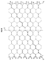
- FIGS 9 to 17 illustrate some possible variants according to the present invention. These figures are diagrams of the honeycomb lining, seen in a section at the level of the reference surface. Direction D will designate in these figures the generating direction of the cylinders.
- Reference C designates the line along which the trim cylinder was cut to draw the developed surface.
- the two lines designated by the reference C touch when the cylinder and reconstituted.
- Figure 9 shows the development of a honeycomb structure formed from a single helical strip which corresponds to case 2 of the second example.
- the length of the segments 68 and 71 is equal to m
- the lengths of the walls 69 and 72 are identical equal to m1
- the walls 67 and 70 are of identical lengths equal to m2.
- m1 is greater than m and m2 is less than m.
- the difference between m1 and m2 greater than m and m2 is less than m.
- the difference between m1 and m2 makes it possible to move the helical strip with respect to a plane perpendicular to the axis of the cylinder by the height H of a mesh over two turns.
- the lining thus formed is flattenable because the cumulative length of the walls 67, 68 and 69 belonging to the same cell and located on the same side of a line joining two bonding zones is equal to the cumulative length walls 70, 71 and 72 belonging to this same cell but located on the other side of said line.
- the average length of m1 and m2 can be equal to m.
- Two successive turns of the propeller have a length which differs slightly from m2 - m1.
- propellers of constant diameters the difference being compensated for by a slight modification of the angle of the walls of the cells.
- FIG. 10 represents a honeycomb structure comprising regular hexagons formed from a single helical strip, but comprises areas of triple assembly.
- FIG. 11 represents a honeycomb structure with a circumferential mesh comprising several helices 74, 75, 76, 77, 78 and 79 nested with one another.
- the arrows indicate the walls with parallel sides.
- FIG. 12 illustrates the case of simple crowns 73 whose reference line is homothetic to the curve which generates the surface to be covered. This case was described in example 2, case 1.
- FIG. 13 illustrates the case of a longitudinal mesh lining produced from several propellers 80, 81, 82, 83, 84 and 85.
- FIG. 14 illustrates the case of a circumferential mesh lining comprising crowns 86, 87 and 88 which each leaves more than one mesh height H a plane P1 perpendicular to the axis of the cylinder passing through a point of this crown 87.
- the reference lines of these crowns are not homothetic with the line generating the surface to be covered.
- the arrows designate the walls with parallel sides.
- FIG. 15 represents a lining with neither circumferential nor radial meshes.
- This structure comprises several propellers 89, 90 and 91 nested one to the other.
- the arrows indicate the walls with parallel sides which generally correspond to the walls whose direction of intersection with the reference surface 92 is closest to the generating direction D.
- FIGS. 15 and 16 illustrate non-regular hexagonal meshes but which nevertheless remain flattenable.
- the gasket according to the present invention can be used to thermally insulate pipes used in particular for the transport of hot or cold fluids, such as petroleum products (heavy oils or liquefied natural gas).
- the cells of the lining may be filled with materials having thermal insulation properties and the lining may be covered with at least one sheath.
- the thermal insulation material may be a foamed product.
- Such structures can also be used as light core material in non-planar sandwich structures.
Landscapes
- Engineering & Computer Science (AREA)
- Mechanical Engineering (AREA)
- General Engineering & Computer Science (AREA)
- Laminated Bodies (AREA)
- Thermal Insulation (AREA)
- Application Of Or Painting With Fluid Materials (AREA)
- Toys (AREA)
- Road Repair (AREA)
- Sewage (AREA)
Claims (8)
- Verfahren zum Herstellen einer zell- bzw. wabenförmigen Struktur, die dazu bestimmt ist, eine gegebenenfalls fiktive zylindrische Oberfläche zu überdecken, die folgenden Stufen umfassend:a) man definiert ein Band, das sich im wesentlichen in einer Ebene erstreckt und gekrümmt ist, d.h. welches wenigstens einen nicht geradlinigen Teil umfaßt, wobei dieses Band begrenzt ist durch eine homothetische Krümmung (64) der Außenkrümmung, welche den geraden Querschnitt des Zylinders in einem gegebenen Verhältnis und durch eine erhaltene Krümmung begrenzt, indem man unter einer gewissen Entfernung (e) nach außen eine Krümmung (65) parallel zur hypothetischen Krümmung aufträgt, wobei (e) die Dicke dieser Struktur darstellt;b) man definiert auf diesem Band eine Bezugslinie (59) parallel zum Innenrand dieses Bandes gegebener Länge;c) man markiert auf dieser Bezugslinie Punktepaare (C₀, C₁ - C₂, C₃ - C2j, C2j+1), die unter regelmäßigem Abstand vorgesehen sind und aufeinander folgen, um die Wandungen der Zellen zu begrenzen;d) für jeden der Punkte eines Paares definiert man eine Gerade parallel zu einer quer verlaufenden Geraden (L) einer Richtung, die im wesentlichen senkrecht entweder zu dieser Bezugslinie oder zu der die beiden Punkte dieses Paares verbindenden Geraden ist, wobei diese beiden Geraden auf diesem Band eine Wandung mit sog. parallelen Seiten begrenzen; unde) man baut untereinander zusammen entweder Wände mit parallelen Seiten oder Wände mit nicht parallelen Seiten, um diese Struktur zu erhalten.
- Verfahren zum Herstellen einer zell- bzw. wabenförmigen Struktur, die dazu bestimmt ist, eine gegebenenfalls fiktive zylindrische Oberfläche zu überdecken, die folgenden Stufen umfassend:a) man definiert ein spiralförmiges Band, das aus im wesentlichen planen Windungen und gegebenem Durchmesser geformt ist und eine radiale Höhe (e) entsprechend der Dicke dieser Struktur aufweist;b) man definiert auf diesem Band eine kreisförmige Bezugslinie;c) man markiert auf dieser Bezugslinie Punktepaare (C₀, C₁ - C₂, C₃ - C2j, C 2j+1), die regelmäßig und aufeinanderfolgend zur Begrenzung der Wandungen der Zellen unter Abstand angeordnet sind;d) für jeden der Punkte eines Paares definiert man eine Gerade parallel zu einer transversal verlaufenden Geraden (L), deren Richtung im wesentlichen senkrecht entweder zur Bezugslinie oder zu der die beiden Punkte des Paares verbindenden Geraden ist, wobei dieser beiden Geraden auf diesem Band eine Wandung mit sog. parallelen Seiten begrenzen;e) man fügt untereinander entweder Wandungen mit parallelen Seiten oder Wandungen mit nicht parallelen Seiten zum Erhalt dieser Struktur zusammen.
- Verfahren nach einem der Ansprüche 1 oder 2, dadurch gekennzeichnet, daß diese transversale Gerade im wesentlichen benachbart dem Punkt verläuft, der sich in der Mitte des geradlinigen oder krummlinigen Segments befindet und durch die die beiden Punkte dieses Paares verbindende Bezugslinie definiert ist.
- Verfahren nach einem der Ansprüche 1 bis 3, dadurch gekennzeichnet, daß man dieses Band so anordnet, daß wenigstens eine Zelle geformt wird, die wenigstens eine Wand (92) mit zwei Kanten im wesentlichen parallel verlaufend umfaßt, die eine erste Ebene bilden und wenigstens eine Wandung mit zwei nicht parallelen koplanaren Kanten umfaßt, die eine zweite Ebene bilden und damit die so gebildete Zelle derart ist, daß der durch die erste Ebene mit der durch eine der Erzeugenden (d) des Zylinders gebildeten Richtung kleiner als der durch die zweite Ebene mit eben dieser Richtung gebildete Winkel ist.
- Verfahren nach einem der Ansprüche 1 bis 4, dadurch gekennzeichnet, daß man mehrere im wesentlichen spiralförmige Bänder verwendet.
- Verfahren nach einem der Ansprüche 1 bis 5, dadurch gekennzeichnet, daß man mehrere Bänder verwendet, wobei jedes dieser Bänder sich auf sich selbst schließt.
- Verfahren nach einem der Ansprüche 1 bis 6, dadurch gekennzeichnet, daß man das Band so anordnet, daß wenigstens eine Wand zu einer Eben im wesentlilchen senkrecht zur Richtung der Erzeugenden dieses Zylinders gehört.
- Verfahren nach einem der Ansprüche 1 bis 7, dadurch gekennzeichnet, daß man das Band so anordnet, daß wenigstens eine Wand zu einer Ebene im wesentlichen parallel zur Richtung einer Erzeugenden des Zylinders gehört.
Applications Claiming Priority (2)
| Application Number | Priority Date | Filing Date | Title |
|---|---|---|---|
| FR8407282A FR2564037B1 (fr) | 1984-05-11 | 1984-05-11 | Structure alveolaire destinee a recouvrir une surface curviligne et procede de realisation |
| FR8407282 | 1984-05-11 |
Publications (2)
| Publication Number | Publication Date |
|---|---|
| EP0167416A1 EP0167416A1 (de) | 1986-01-08 |
| EP0167416B1 true EP0167416B1 (de) | 1992-02-26 |
Family
ID=9303878
Family Applications (1)
| Application Number | Title | Priority Date | Filing Date |
|---|---|---|---|
| EP85400840A Expired - Lifetime EP0167416B1 (de) | 1984-05-11 | 1985-04-29 | Verfahren zur Herstellung einer zellförmigen Struktur zum Bedecken einer gekrümmten Oberfläche |
Country Status (10)
| Country | Link |
|---|---|
| US (1) | US4777070A (de) |
| EP (1) | EP0167416B1 (de) |
| JP (1) | JPH0622957B2 (de) |
| BR (1) | BR8502310A (de) |
| CA (1) | CA1261724A (de) |
| DE (1) | DE3585419D1 (de) |
| ES (2) | ES8702830A1 (de) |
| FR (1) | FR2564037B1 (de) |
| NO (1) | NO165585C (de) |
| OA (1) | OA08095A (de) |
Families Citing this family (10)
| Publication number | Priority date | Publication date | Assignee | Title |
|---|---|---|---|---|
| EP0284699B1 (de) * | 1987-03-10 | 1990-08-01 | Samuel Prof.Dr.Sc.Nat. Steinemann | Intermetallische Verbindung und ihre Verwendung |
| JPH05161933A (ja) * | 1991-11-21 | 1993-06-29 | Hitachi Ltd | 曲面ハニカムパネルおよびその製造方法 |
| JP2664119B2 (ja) * | 1992-11-20 | 1997-10-15 | 日本碍子株式会社 | 曲りハニカム構造体 |
| JP2664118B2 (ja) * | 1992-11-20 | 1997-10-15 | 日本碍子株式会社 | 曲りハニカム構造体 |
| JP3073854B2 (ja) * | 1993-03-31 | 2000-08-07 | 日本碍子株式会社 | ハニカム構造体 |
| US5633066A (en) * | 1994-03-21 | 1997-05-27 | Corning Incorporated | Honeycomb structures having non-parallel cells and method of making |
| FR2720488B1 (fr) | 1994-05-24 | 1996-07-12 | Inst Francais Du Petrole | Dispositif rotatif de transfert de chaleur et d'épuration thermique appliqué à des effluents gazeux. |
| DE59707399D1 (de) * | 1996-11-11 | 2002-07-11 | Fleissner Maschf Gmbh Co | Vorrichtung zum hydrodynamischen Vernadeln von Vliesen, Tissue od. dgl. |
| CA2328628A1 (en) * | 1999-12-21 | 2001-06-21 | Cecile J. Schoenheider | Moldable compositions |
| US9221230B2 (en) * | 2011-08-22 | 2015-12-29 | The Boeing Company | Honeycomb structure |
Family Cites Families (22)
| Publication number | Priority date | Publication date | Assignee | Title |
|---|---|---|---|---|
| CA727074A (en) * | 1966-02-01 | Union Bag-Camp Paper Corporation | Flexible self-draping honeycomb and method of manufacture | |
| US2815795A (en) * | 1955-02-16 | 1957-12-10 | Armstrong Cork Co | Honeycomb core material and method of fabricating the same |
| US3013584A (en) * | 1955-03-28 | 1961-12-19 | Gar Wood Ind Inc | Supporting members |
| CH343803A (fr) * | 1956-04-12 | 1959-12-31 | Dufaylite Dev Ltd | Elément cellulaire et procédé pour sa fabrication |
| US3016315A (en) * | 1958-10-08 | 1962-01-09 | Carl D Hall Jr | Honeycomb structure and method |
| US3033734A (en) * | 1959-08-27 | 1962-05-08 | Gen Electric | Honeycomb structures |
| US3100928A (en) * | 1960-09-15 | 1963-08-20 | Metal Tech Inc | Honeycomb openwork |
| US3139375A (en) * | 1960-09-15 | 1964-06-30 | Metal Tech Inc | Suction roll assembly |
| US3109766A (en) * | 1960-09-21 | 1963-11-05 | Norris Charles Brazer | Cellular core for curved surfaces |
| US3104194A (en) * | 1962-01-30 | 1963-09-17 | Adam T Zahorski | Panel structure |
| GB961785A (en) * | 1962-06-28 | 1964-06-24 | Ciba Ltd | Manufacture of honeycomb structures |
| US3212189A (en) * | 1962-07-18 | 1965-10-19 | Western Geophysical Co | Marine navigation procedure |
| US3259961A (en) * | 1964-12-21 | 1966-07-12 | Metal Tech Inc | Cylindrical honeycomb roll |
| US3590453A (en) * | 1968-06-19 | 1971-07-06 | Metal Tech Inc | Honeycomb roll |
| US3589033A (en) * | 1969-02-26 | 1971-06-29 | Metal Tech Inc | Honeycomb roll assembly for treating paper with felts |
| FR2129032A5 (de) * | 1971-03-12 | 1972-10-27 | Creusot Loire | |
| DE2454792A1 (de) * | 1973-11-21 | 1975-06-19 | Ciba Geigy Ag | Zellenartige struktur und verfahren zu ihrer herstellung |
| US4001473A (en) * | 1976-02-19 | 1977-01-04 | Rohr Industries, Inc. | Sound attenuating structural honeycomb sandwich material |
| FR2464817A1 (fr) * | 1979-09-06 | 1981-03-20 | Commissariat Energie Atomique | Procede et dispositif de fabrication de modules alveolaires |
| DE3210320C2 (de) * | 1982-03-20 | 1986-02-06 | J.M. Voith Gmbh, 7920 Heidenheim | Saugwalze für Papiermaschinen |
| US4457963A (en) * | 1982-04-02 | 1984-07-03 | Ittner Nelson C | Honeycomb manufacturing method and product |
| US4513041A (en) * | 1983-08-12 | 1985-04-23 | Delluc Rene | Tubular vacuum-tight enclosures for thermal and acoustical insulating panels |
-
1984
- 1984-05-11 FR FR8407282A patent/FR2564037B1/fr not_active Expired
-
1985
- 1985-04-29 DE DE8585400840T patent/DE3585419D1/de not_active Expired - Lifetime
- 1985-04-29 EP EP85400840A patent/EP0167416B1/de not_active Expired - Lifetime
- 1985-05-07 US US06/731,403 patent/US4777070A/en not_active Expired - Fee Related
- 1985-05-09 NO NO851854A patent/NO165585C/no unknown
- 1985-05-10 JP JP60099467A patent/JPH0622957B2/ja not_active Expired - Lifetime
- 1985-05-10 ES ES543064A patent/ES8702830A1/es not_active Expired
- 1985-05-10 CA CA000481252A patent/CA1261724A/fr not_active Expired
- 1985-05-10 BR BR8502310A patent/BR8502310A/pt not_active IP Right Cessation
- 1985-05-10 OA OA58588A patent/OA08095A/xx unknown
-
1986
- 1986-03-05 ES ES552700A patent/ES8900154A1/es not_active Expired
Also Published As
| Publication number | Publication date |
|---|---|
| ES8900154A1 (es) | 1989-03-01 |
| ES552700A0 (es) | 1989-03-01 |
| BR8502310A (pt) | 1986-01-21 |
| NO851854L (no) | 1985-11-12 |
| FR2564037A1 (fr) | 1985-11-15 |
| FR2564037B1 (fr) | 1986-10-03 |
| US4777070A (en) | 1988-10-11 |
| NO165585B (no) | 1990-11-26 |
| ES8702830A1 (es) | 1987-01-16 |
| NO165585C (no) | 1991-03-06 |
| JPS6183026A (ja) | 1986-04-26 |
| ES543064A0 (es) | 1987-01-16 |
| DE3585419D1 (de) | 1992-04-02 |
| CA1261724A (fr) | 1989-09-26 |
| JPH0622957B2 (ja) | 1994-03-30 |
| EP0167416A1 (de) | 1986-01-08 |
| OA08095A (fr) | 1987-03-31 |
Similar Documents
| Publication | Publication Date | Title |
|---|---|---|
| EP0494299B1 (de) | Karkasse und flexible rohrleitung mit einer solchen karkasse | |
| EP0890056B1 (de) | Leitungsrohr des typs doppelwärmedämpfungsmantel | |
| EP0167416A1 (de) | Verfahren zur Herstellung einer zellförmigen Struktur zum Bedecken einer gekrümmten Oberfläche | |
| EP1056529B1 (de) | Filterelement insbesondere für brennkraftmaschine | |
| WO2009066036A2 (fr) | Structure a ame alveolaire pour panneau acoustique | |
| WO2022200717A1 (fr) | Pneumatique comprenant une structure de rigidification endurante | |
| EP0877887A1 (de) | Biegsame rohrleitung mit einem gasdichten innenwellenrohr aus metall | |
| FR3088848A1 (fr) | Procédé de fabrication d’un élément acoustique d’une structure d’absorption acoustique à partir d’au moins une feuille de matière | |
| EP0504038A1 (de) | Filterkartuschen mit plissiertem Filterelement | |
| FR2630502A1 (fr) | Propulseur composite a ailes composites integrees et son procede de fabrication | |
| EP4411726A1 (de) | Wabenstruktur einer schalldämmplatte mit mindestens einer trennwand, die zum vibrieren einer gewünschten frequenz konfiguriert ist, und verfahren zur herstellung dieser wabenstruktur | |
| FR2693545A1 (fr) | Echangeur de chaleur à plusieurs rangées de tubes, notamment pour véhicules automobiles. | |
| FR2647198A1 (fr) | Echangeur thermique a conduits a plaques | |
| JP4384812B2 (ja) | 中を流体が流れ得る複数のチャネルを備えたハニカム構造体を製造するための方法およびシートメタルの積層体 | |
| FR3038238A1 (fr) | Element separateur pour un separateur de liquide, milieu separateur et separateur de liquide et son procede de fabrication | |
| WO2025114533A1 (fr) | Réservoir pour gaz sous pression | |
| WO2013007524A1 (fr) | Pneumatique pliable, procede de pliage et utilisation | |
| FR2696772A1 (fr) | Coffrage et son procédé de fabrication. | |
| FR2585771A1 (fr) | Procede de fabrication d'un cone de sortie de tuyere extensible de moteur-fusee et cette tuyere | |
| FR2755468A1 (fr) | Etage de rotor de turbomachine renforce par des fibres | |
| FR2664674A1 (fr) | Element isolant, en forme de manchon, pour tubes. | |
| WO1993025443A1 (fr) | Boite de section polygonale en une matiere en feuille de carton ondule, a renfort interne, et procede de fabrication d'une telle boite | |
| EP4690180A1 (de) | Akustikplatte für eine flugzeugantriebsanordnung und verfahren zur herstellung davon | |
| FR2845728A1 (fr) | Procede pour fabriquer un boitier de catalyseur | |
| FR3161597A1 (fr) | Procédé de fabrication d’une âme alvéolaire pour panneau d’atténuation acoustique |
Legal Events
| Date | Code | Title | Description |
|---|---|---|---|
| PUAI | Public reference made under article 153(3) epc to a published international application that has entered the european phase |
Free format text: ORIGINAL CODE: 0009012 |
|
| AK | Designated contracting states |
Designated state(s): BE CH DE GB IT LI NL SE |
|
| 17P | Request for examination filed |
Effective date: 19860227 |
|
| 17Q | First examination report despatched |
Effective date: 19870508 |
|
| ITF | It: translation for a ep patent filed | ||
| GRAA | (expected) grant |
Free format text: ORIGINAL CODE: 0009210 |
|
| AK | Designated contracting states |
Kind code of ref document: B1 Designated state(s): BE CH DE GB IT LI NL SE |
|
| REF | Corresponds to: |
Ref document number: 3585419 Country of ref document: DE Date of ref document: 19920402 |
|
| GBT | Gb: translation of ep patent filed (gb section 77(6)(a)/1977) | ||
| PLBE | No opposition filed within time limit |
Free format text: ORIGINAL CODE: 0009261 |
|
| STAA | Information on the status of an ep patent application or granted ep patent |
Free format text: STATUS: NO OPPOSITION FILED WITHIN TIME LIMIT |
|
| 26N | No opposition filed | ||
| EAL | Se: european patent in force in sweden |
Ref document number: 85400840.6 |
|
| PGFP | Annual fee paid to national office [announced via postgrant information from national office to epo] |
Ref country code: SE Payment date: 19970317 Year of fee payment: 13 Ref country code: GB Payment date: 19970317 Year of fee payment: 13 |
|
| PGFP | Annual fee paid to national office [announced via postgrant information from national office to epo] |
Ref country code: BE Payment date: 19970423 Year of fee payment: 13 |
|
| PGFP | Annual fee paid to national office [announced via postgrant information from national office to epo] |
Ref country code: NL Payment date: 19970430 Year of fee payment: 13 |
|
| PGFP | Annual fee paid to national office [announced via postgrant information from national office to epo] |
Ref country code: DE Payment date: 19970522 Year of fee payment: 13 |
|
| PGFP | Annual fee paid to national office [announced via postgrant information from national office to epo] |
Ref country code: CH Payment date: 19970630 Year of fee payment: 13 |
|
| PG25 | Lapsed in a contracting state [announced via postgrant information from national office to epo] |
Ref country code: GB Free format text: LAPSE BECAUSE OF NON-PAYMENT OF DUE FEES Effective date: 19980429 |
|
| PG25 | Lapsed in a contracting state [announced via postgrant information from national office to epo] |
Ref country code: SE Free format text: LAPSE BECAUSE OF NON-PAYMENT OF DUE FEES Effective date: 19980430 Ref country code: LI Free format text: LAPSE BECAUSE OF NON-PAYMENT OF DUE FEES Effective date: 19980430 Ref country code: CH Free format text: LAPSE BECAUSE OF NON-PAYMENT OF DUE FEES Effective date: 19980430 Ref country code: BE Free format text: LAPSE BECAUSE OF NON-PAYMENT OF DUE FEES Effective date: 19980430 |
|
| BERE | Be: lapsed |
Owner name: INSTITUT FRANCAIS DU PETROLE Effective date: 19980430 |
|
| PG25 | Lapsed in a contracting state [announced via postgrant information from national office to epo] |
Ref country code: NL Free format text: LAPSE BECAUSE OF NON-PAYMENT OF DUE FEES Effective date: 19981101 |
|
| REG | Reference to a national code |
Ref country code: CH Ref legal event code: PL |
|
| GBPC | Gb: european patent ceased through non-payment of renewal fee |
Effective date: 19980429 |
|
| NLV4 | Nl: lapsed or anulled due to non-payment of the annual fee |
Effective date: 19981101 |
|
| EUG | Se: european patent has lapsed |
Ref document number: 85400840.6 |
|
| PG25 | Lapsed in a contracting state [announced via postgrant information from national office to epo] |
Ref country code: DE Free format text: LAPSE BECAUSE OF NON-PAYMENT OF DUE FEES Effective date: 19990302 |