EP0167433A1 - Provisorische Verbindungsvorrichtung von zwei aneinanderstossenden Teilen im Raum - Google Patents
Provisorische Verbindungsvorrichtung von zwei aneinanderstossenden Teilen im Raum Download PDFInfo
- Publication number
- EP0167433A1 EP0167433A1 EP85401100A EP85401100A EP0167433A1 EP 0167433 A1 EP0167433 A1 EP 0167433A1 EP 85401100 A EP85401100 A EP 85401100A EP 85401100 A EP85401100 A EP 85401100A EP 0167433 A1 EP0167433 A1 EP 0167433A1
- Authority
- EP
- European Patent Office
- Prior art keywords
- retaining members
- parts
- edge
- members
- contact surface
- Prior art date
- Legal status (The legal status is an assumption and is not a legal conclusion. Google has not performed a legal analysis and makes no representation as to the accuracy of the status listed.)
- Granted
Links
Images
Classifications
-
- B—PERFORMING OPERATIONS; TRANSPORTING
- B64—AIRCRAFT; AVIATION; COSMONAUTICS
- B64G—COSMONAUTICS; VEHICLES OR EQUIPMENT THEREFOR
- B64G1/00—Cosmonautic vehicles
- B64G1/22—Parts of, or equipment specially adapted for fitting in or to, cosmonautic vehicles
- B64G1/64—Systems for coupling or separating cosmonautic vehicles or parts thereof, e.g. docking arrangements
- B64G1/645—Separators
-
- B—PERFORMING OPERATIONS; TRANSPORTING
- B64—AIRCRAFT; AVIATION; COSMONAUTICS
- B64G—COSMONAUTICS; VEHICLES OR EQUIPMENT THEREFOR
- B64G1/00—Cosmonautic vehicles
- B64G1/22—Parts of, or equipment specially adapted for fitting in or to, cosmonautic vehicles
- B64G1/42—Arrangements or adaptations of power supply systems
- B64G1/44—Arrangements or adaptations of power supply systems using radiation, e.g. deployable solar arrays
-
- B—PERFORMING OPERATIONS; TRANSPORTING
- B64—AIRCRAFT; AVIATION; COSMONAUTICS
- B64G—COSMONAUTICS; VEHICLES OR EQUIPMENT THEREFOR
- B64G1/00—Cosmonautic vehicles
- B64G1/22—Parts of, or equipment specially adapted for fitting in or to, cosmonautic vehicles
- B64G1/64—Systems for coupling or separating cosmonautic vehicles or parts thereof, e.g. docking arrangements
- B64G1/641—Interstage or payload connectors
-
- F—MECHANICAL ENGINEERING; LIGHTING; HEATING; WEAPONS; BLASTING
- F16—ENGINEERING ELEMENTS AND UNITS; GENERAL MEASURES FOR PRODUCING AND MAINTAINING EFFECTIVE FUNCTIONING OF MACHINES OR INSTALLATIONS; THERMAL INSULATION IN GENERAL
- F16B—DEVICES FOR FASTENING OR SECURING CONSTRUCTIONAL ELEMENTS OR MACHINE PARTS TOGETHER, e.g. NAILS, BOLTS, CIRCLIPS, CLAMPS, CLIPS OR WEDGES; JOINTS OR JOINTING
- F16B2200/00—Constructional details of connections not covered for in other groups of this subclass
- F16B2200/30—Dovetail-like connections
-
- F—MECHANICAL ENGINEERING; LIGHTING; HEATING; WEAPONS; BLASTING
- F16—ENGINEERING ELEMENTS AND UNITS; GENERAL MEASURES FOR PRODUCING AND MAINTAINING EFFECTIVE FUNCTIONING OF MACHINES OR INSTALLATIONS; THERMAL INSULATION IN GENERAL
- F16B—DEVICES FOR FASTENING OR SECURING CONSTRUCTIONAL ELEMENTS OR MACHINE PARTS TOGETHER, e.g. NAILS, BOLTS, CIRCLIPS, CLAMPS, CLIPS OR WEDGES; JOINTS OR JOINTING
- F16B2200/00—Constructional details of connections not covered for in other groups of this subclass
- F16B2200/50—Flanged connections
- F16B2200/503—Flanged connections the flange being separate from the elements to be connected
-
- Y—GENERAL TAGGING OF NEW TECHNOLOGICAL DEVELOPMENTS; GENERAL TAGGING OF CROSS-SECTIONAL TECHNOLOGIES SPANNING OVER SEVERAL SECTIONS OF THE IPC; TECHNICAL SUBJECTS COVERED BY FORMER USPC CROSS-REFERENCE ART COLLECTIONS [XRACs] AND DIGESTS
- Y10—TECHNICAL SUBJECTS COVERED BY FORMER USPC
- Y10T—TECHNICAL SUBJECTS COVERED BY FORMER US CLASSIFICATION
- Y10T403/00—Joints and connections
- Y10T403/16—Joints and connections with adjunctive protector, broken parts retainer, repair, assembly or disassembly feature
- Y10T403/1616—Position or guide means
-
- Y—GENERAL TAGGING OF NEW TECHNOLOGICAL DEVELOPMENTS; GENERAL TAGGING OF CROSS-SECTIONAL TECHNOLOGIES SPANNING OVER SEVERAL SECTIONS OF THE IPC; TECHNICAL SUBJECTS COVERED BY FORMER USPC CROSS-REFERENCE ART COLLECTIONS [XRACs] AND DIGESTS
- Y10—TECHNICAL SUBJECTS COVERED BY FORMER USPC
- Y10T—TECHNICAL SUBJECTS COVERED BY FORMER US CLASSIFICATION
- Y10T403/00—Joints and connections
- Y10T403/61—Side slide: elongated co-linear members
Definitions
- the invention relates to a provisional securing device in the space of two pieces edge to edge such as is used in particular for the temporary closure of space containers, intended for example for temporary storage of solar panels which should only deploy after putting a carrier satellite into orbit.
- such space containers generally consist of a hollow body, for example parallelipiped, closed by at least one cover, and the devices for the temporary securing of their constituent parts comprise an automatic release mechanism adapted to allow , or even cause, the separation of these parts in response to opening trigger orders, prior to the deployment of the contents of these containers.
- the subject of the present invention is a device for temporarily securing two pieces edge to edge, such as for example two pieces of a space container, which is adapted, on the one hand, to be transmitted between these pieces, in addition to efforts of keeping in contact, shear forces in the plane of their contact surface and, on the other hand, allowing reliable automatic release of these parts one with respect to the other in response to an order of opening ;
- the invention particularly relates to a device of the aforementioned type which is adapted to be implemented in a harsh environment, of the space vacuum type, in which mechanical structures are commonly the seat of very high temperature gradients, or even sudden variations in temperature over significant deviations depending on their orientation towards the sun.
- the invention further aims to optimize the geometry of the contact surfaces between the parts to be secured so as to minimize their relative clearances.
- the invention provides for this purpose a provisional securing device in the space of two pieces edge to edge along a contact surface, of the kind comprising retaining members distributed in pairs on either side of this contact surface on each of said parts respectively and of the temporary connecting members to keep the retaining members of each pair coupled, as well as an automatic release mechanism comprising a coordinating element connected to the temporary connecting members and adapted to release these last vis-à-vis the retaining members under the action of an opening mechanism, characterized in that the retaining members of the same pair are provided with complementary reliefs for their retaining one vis-à-vis screw of the other in a longitudinal direction parallel to the contact surface of said parts, in at least one direction, and that these retaining members jointly form a bulge tenon oriented longitudinally ment, engaged in a constricted groove formed in a jumper forming a temporary connecting member.
- the invention particularly recommends that the bulged post and the constricted groove be shaped like a dovetail.
- a device according to the invention ensures the transmission, in both directions, of longitudinal shearing forces provided that successive pairs of retaining members at the opening have complementary reliefs of longitudinal retaining adapted to act in opposite directions.
- the invention recommends that the complementary reliefs of each pair can provide longitudinal retention in both directions. These reliefs can consist of undulations or a broken line succession of inclined sides.
- the invention recommends that these reliefs consist of a tenon and a mortise with substantially parallel sides with, however, preferably an inclination of a few degrees to facilitate separation.
- the jumpers of a device ensure, jointly with the associated retaining members, the transmission between the subject parts of transverse shearing forces, perpendicular to the orientation of the tenons and mortises.
- the invention further recommends the implementation of additional reliefs arranged opposite along the contact surface of the subject parts for their transverse shear retention.
- the reliefs can be combined with the abovementioned reliefs of longitudinal retention.
- the invention recommends that these transverse retaining reliefs be inserted along the contact surface between pairs of retaining members to ensure, as continuously as possible, transverse retaining of the parts throughout their contact surface. .
- These reliefs are advantageously bevels.
- the invention further recommends that the coordinating element connected to the jumpers with a view to their release at the desired time is also connected to a spacer, for example made up of a knife, at least one notch being formed longitudinally close to the surface. contact of the two parts so as to ensure, by cooperation with the spacer, a forced separation of the parts after the release of the connecting members vis-à-vis the retaining members.
- a spacer for example made up of a knife
- the invention recommends that the retaining members, as well as the transverse retaining reliefs, be provided on plates-attached to the parts to be provisionally secured.
- a temporary closure device can be assembled and then fixed as a whole on the parts to be secured: the assembly operations of this device, and of the parts to be secured, are thereby simplified and facilitated.
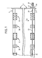
- Figures 1 to 6 illustrate by way of example a temporary securing device according to the invention applied to the temporary closure of a space container formed by a generally rectangular hollow body 1 closed by two lids 2 and 2 '.
- a substantially complete device according to the invention is shown in the lower part of Figure 1 and in Figure 6, while the upper part of this Figure 1 shows a similar device after removal of the associated automatic release mechanism.
- the provisional securing devices shown by way of example in FIG. 1 mainly comprise, for the edge-to-edge securing of the covers 2 and 2 ′ to the body 1, connection assemblies of the type designated by arrow II in the figure. 1 and shown in detail in FIGS. 2 and 3.
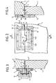
- connection assembly is mounted astride the respective edges 3 and 4 of the container body 1 and the cover 2 joined against a contact surface 5. These edges define a continuous outer surface on which are mounted two retaining members 6 and 7 jointly defining a swollen post in two parts 8 and 9 joined.
- these members 6 and 7 are provided with bores 10, in order to be attached, in particular by screws, to the edges 3 and 4 of the parts to be secured.
- the swollen post is, in the example shown, shaped like a dovetail and has a trapezoidal section; it is engaged in a constricted groove 11 formed in a jumper 12, which, by action on the retaining members 6 and 7, ensures the edge-to-edge retention of the parts 1 and 2 against perpendicular opening forces T to the contact surface 5 of the two parts.
- the constricted groove 11 is a dovetail mortise.
- the bulged tenon 8 and 9 and the groove 10 are oriented longitudinally, parallel to the contact surface 5 and to the external surface of the parts to be secured.
- the retaining members 6 and 7 have complementary reliefs.
- these reliefs are constituted by a tenon 13 secured to the member 7, engaged in a mortise 14 formed in the member 6.
- This tenon and this mortise are oriented transversely and provide a longitudinal retention of the members 6 and 7 in both directions (C 1 shear forces).
- Their sides 13A and 14A are substantially perpendicular to the contact surface 5, preferably with an inclination of a few degrees with respect to T.
- the retaining members 6 and 7 are placed side by side on a generally planar surface , parallel to the contact surface 5 of parts 1 and 2 and, moreover, located in the extension of the latter.
- the confrontation surface of the retaining members is inclined at least around a transverse axis, preferably composed of a plurality of sections successive opposing inclinations so as to define on one of the members at least one outgoing angle engaged in a re-entrant angle defined on the other member.
- a provisional securing device generally comprises a plurality of connection assemblies of the aforementioned type, distributed along the contact surface 5. Between these assemblies are advantageously arranged additional transverse retaining assemblies, one of which is shown as an example in Figure 4.
- the additional assembly shown in Figure 4 consists of two pads or heels 15 and 16 respectively reported at the edge 3 of the body 1 and the edge 4 of the cover 2, faced in two bevelled edges 15A and 16A.
- these sections advantageously intercept the extension of the contact surface 5 of the edges 3 and 4: in this way, one (15A) of these sections is engaged in a groove defined by the associated section (16A) and the edge that carries it.
- This configuration allows the transmission of transverse shearing forces in both directions, between edges 3 and 4 (forces denoted C 2 ).
- the facing surfaces of the retaining members 6 and 7 are likewise beveled.
- the retaining members 6 and 7 and the rider 12 also jointly provide some transverse retention of the edges 3 and 4.
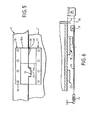
- the edge-to-edge securing device also advantageously comprises a separation assembly illustrated in FIG. 5. It comprises two plates 17 and 18 respectively attached to the container body 1 and to the cover 2, faced on bearing surfaces substantially parallel to the contact surface of the parts 1 and 2 secured, but which deviate from one another in -a longitudinal direction, so as to define a spacing slot 19 whose purpose will appear later.
- this slot is defined by a bevelled ramp 20 formed on only one (17) of the plates.
- This slot 19 is advantageously provided on portions 17A and 18A of the plates which have a transverse dimension greater than that of the connection assemblies or additional transverse retaining assemblies.
- these plates 17 and 18 are also interpenetrated by a lug 21 of a plate (18) engaged in a mortise 22 formed on the other plate (17).
- the plates 17 and 18 are further shaped so as to define, like the members 6 and 7 of FIG. 2, a bulged tenon engaged in a constricted groove formed on a jumper similar to the part 12.
- the plates 15 to 18 include, like the members 6 and 7, bores 10 for their attachment to the parts 1 and 2 to be secured.
- a device according to the invention comprises a mechanical release mechanism partially shown in top view in FIG. 6.
- This mechanism mainly comprises a coordination and transmission element 23, for example consisting of a rod or a blade, connected to all the jumpers of the type shown in Figures 2 and 3 and adapted to disengage them from the retaining members associated under the action of a drive member 24, (carried by one or the other of the subject parts), in response to an opening release order.
- a coordination and transmission element 23 for example consisting of a rod or a blade, connected to all the jumpers of the type shown in Figures 2 and 3 and adapted to disengage them from the retaining members associated under the action of a drive member 24, (carried by one or the other of the subject parts), in response to an opening release order.
- the drive member is a spring held taut by a locking device 25, advantageously allowing a tension adjustment, connected to the coordination element by a cable 26 passing through a triggering member.
- opening 27 for example of the cable cutter type with pyrotechnic control.
- the drive member, the locking device and the trigger member jointly constitute an opening mechanism.
- the coordinating element 23 also advantageously comprises a knife 28 intended to engage, after the jumpers 12 have been released from the associated retaining members, in the slot 19 of the separation assembly 17-18 .
- this knife 28 thus forces the two parts 1 and 2 to move apart despite possible residual friction originating in particular from thermal or plastic deformations likely to occur in particular in the various tenon and mortise engagements.
- the drive member is a motor, for example of the pyrotechnic type.
- the coordinating element 23 is advantageously engaged in guide elements (not shown) adapted to leave this element with sufficient longitudinal movement to ensure the relative clearance of the jumpers and the retaining members, while holding them laterally so as to prevent this element, the associated knife 28 or the jumpers 12 from interfering with the deployment of the contents of the container or with other mechanical or optical elements of the structure to which the container is fixed.
- the knife 28 is advantageously, but not necessarily, arranged at one end of the coordinating element 23; alternatively, this element is provided with knives oriented in the same direction at each end.
- space containers in particular for the storage of solar panels, generally contain a pressurized bladder intended to hold these panels well against each other in a configuration as rigid as possible.
- This bladder in a container equipped according to the invention has the advantage of compensating for any play between the retaining members and the associated jumper thanks to the increased pressure which results therefrom between the sides of the post formed by these members and the sides of the groove of this jumper (parallel to the arrow T in Figure 3).
- This bladder is in practice deflated before proceeding to the automatic release phase.
Landscapes
- Engineering & Computer Science (AREA)
- Remote Sensing (AREA)
- Aviation & Aerospace Engineering (AREA)
- Life Sciences & Earth Sciences (AREA)
- Sustainable Development (AREA)
- Connection Of Plates (AREA)
- Load-Engaging Elements For Cranes (AREA)
- Mutual Connection Of Rods And Tubes (AREA)
- Clamps And Clips (AREA)
- Treatment Of Fiber Materials (AREA)
- Diaphragms For Electromechanical Transducers (AREA)
- Cleaning Implements For Floors, Carpets, Furniture, Walls, And The Like (AREA)
Applications Claiming Priority (2)
| Application Number | Priority Date | Filing Date | Title |
|---|---|---|---|
| FR8408783 | 1984-06-05 | ||
| FR8408783A FR2565302B1 (fr) | 1984-06-05 | 1984-06-05 | Dispositif d'assujettissement provisoire dans l'espace de deux pieces bord a bord |
Publications (2)
| Publication Number | Publication Date |
|---|---|
| EP0167433A1 true EP0167433A1 (de) | 1986-01-08 |
| EP0167433B1 EP0167433B1 (de) | 1987-10-28 |
Family
ID=9304713
Family Applications (1)
| Application Number | Title | Priority Date | Filing Date |
|---|---|---|---|
| EP85401100A Expired EP0167433B1 (de) | 1984-06-05 | 1985-06-04 | Provisorische Verbindungsvorrichtung von zwei aneinanderstossenden Teilen im Raum |
Country Status (6)
| Country | Link |
|---|---|
| US (1) | US4641985A (de) |
| EP (1) | EP0167433B1 (de) |
| JP (1) | JPH0729639B2 (de) |
| CA (1) | CA1243186A (de) |
| DE (1) | DE3560818D1 (de) |
| FR (1) | FR2565302B1 (de) |
Cited By (5)
| Publication number | Priority date | Publication date | Assignee | Title |
|---|---|---|---|---|
| WO1987007235A3 (en) * | 1986-05-27 | 1987-12-17 | Hughes Aircraft Co | Clamping connection assembly for spacecraft |
| US4747566A (en) * | 1986-05-06 | 1988-05-31 | Messerschmitt-Boelkow-Blohm Gmbh | Apparatus for partially unfolding solar collectors |
| EP0237558B1 (de) * | 1985-09-13 | 1992-01-22 | Erik Olsson Ag | Kontinuierliche giessanlage und verfahren |
| US6076467A (en) * | 1997-09-26 | 2000-06-20 | Construcciones Aeronauticas, S.A. | System for attaching and separating satellites |
| US12605482B2 (en) | 2018-07-10 | 2026-04-21 | Targan, Inc. | Systems and methods of preparing and delivering oocyst solutions |
Families Citing this family (3)
| Publication number | Priority date | Publication date | Assignee | Title |
|---|---|---|---|---|
| US5107639A (en) * | 1989-12-12 | 1992-04-28 | Kenneth Van Wezel | Portable and collapsible building structure |
| US6164477A (en) | 1997-11-20 | 2000-12-26 | The Boeing Company | Combined mortise and tenon joint feature |
| US7367738B2 (en) | 2002-09-23 | 2008-05-06 | The Boeing Company | Apparatus and method for releaseably joining elements |
Citations (6)
| Publication number | Priority date | Publication date | Assignee | Title |
|---|---|---|---|---|
| US3091487A (en) * | 1960-04-14 | 1963-05-28 | William H Gallagher | Clip |
| US3677508A (en) * | 1970-09-21 | 1972-07-18 | Trw Inc | Folding deployable panel structure having roll-up retaining spring for stowage |
| DE2252093A1 (de) * | 1972-10-24 | 1974-05-02 | Messerschmitt Boelkow Blohm | Entfaltbarer ausleger fuer raumflugkoerper |
| US3995685A (en) * | 1975-05-19 | 1976-12-07 | Stanko John J | Foundry flask clamp |
| FR2398663A1 (fr) * | 1977-07-26 | 1979-02-23 | United Kingdom Government | Compartiment d'arrimage de materiel a larguage automatique |
| FR2501155A1 (fr) * | 1981-03-03 | 1982-09-10 | Aerospatiale | Dispositif de liberation mecanique par exemple pour satellite |
Family Cites Families (3)
| Publication number | Priority date | Publication date | Assignee | Title |
|---|---|---|---|---|
| US3820477A (en) * | 1973-05-30 | 1974-06-28 | G Griffin | Table aligning and locking device |
| US4102529A (en) * | 1977-05-06 | 1978-07-25 | Neblung Werner H | Railing system |
| US4350257A (en) * | 1981-01-13 | 1982-09-21 | Delta, Inc. | Kit for assembling toolbox adapted for installation in back of pickup truck and method of assembling the toolbox |
-
1984
- 1984-06-05 FR FR8408783A patent/FR2565302B1/fr not_active Expired
-
1985
- 1985-05-29 CA CA000482734A patent/CA1243186A/en not_active Expired
- 1985-05-31 US US06/739,858 patent/US4641985A/en not_active Expired - Lifetime
- 1985-06-04 DE DE8585401100T patent/DE3560818D1/de not_active Expired
- 1985-06-04 EP EP85401100A patent/EP0167433B1/de not_active Expired
- 1985-06-04 JP JP60121374A patent/JPH0729639B2/ja not_active Expired - Lifetime
Patent Citations (6)
| Publication number | Priority date | Publication date | Assignee | Title |
|---|---|---|---|---|
| US3091487A (en) * | 1960-04-14 | 1963-05-28 | William H Gallagher | Clip |
| US3677508A (en) * | 1970-09-21 | 1972-07-18 | Trw Inc | Folding deployable panel structure having roll-up retaining spring for stowage |
| DE2252093A1 (de) * | 1972-10-24 | 1974-05-02 | Messerschmitt Boelkow Blohm | Entfaltbarer ausleger fuer raumflugkoerper |
| US3995685A (en) * | 1975-05-19 | 1976-12-07 | Stanko John J | Foundry flask clamp |
| FR2398663A1 (fr) * | 1977-07-26 | 1979-02-23 | United Kingdom Government | Compartiment d'arrimage de materiel a larguage automatique |
| FR2501155A1 (fr) * | 1981-03-03 | 1982-09-10 | Aerospatiale | Dispositif de liberation mecanique par exemple pour satellite |
Cited By (5)
| Publication number | Priority date | Publication date | Assignee | Title |
|---|---|---|---|---|
| EP0237558B1 (de) * | 1985-09-13 | 1992-01-22 | Erik Olsson Ag | Kontinuierliche giessanlage und verfahren |
| US4747566A (en) * | 1986-05-06 | 1988-05-31 | Messerschmitt-Boelkow-Blohm Gmbh | Apparatus for partially unfolding solar collectors |
| WO1987007235A3 (en) * | 1986-05-27 | 1987-12-17 | Hughes Aircraft Co | Clamping connection assembly for spacecraft |
| US6076467A (en) * | 1997-09-26 | 2000-06-20 | Construcciones Aeronauticas, S.A. | System for attaching and separating satellites |
| US12605482B2 (en) | 2018-07-10 | 2026-04-21 | Targan, Inc. | Systems and methods of preparing and delivering oocyst solutions |
Also Published As
| Publication number | Publication date |
|---|---|
| JPH0729639B2 (ja) | 1995-04-05 |
| EP0167433B1 (de) | 1987-10-28 |
| CA1243186A (en) | 1988-10-18 |
| FR2565302B1 (fr) | 1986-10-10 |
| DE3560818D1 (en) | 1987-12-03 |
| JPS611600A (ja) | 1986-01-07 |
| FR2565302A1 (fr) | 1985-12-06 |
| US4641985A (en) | 1987-02-10 |
Similar Documents
| Publication | Publication Date | Title |
|---|---|---|
| EP0822364A1 (de) | Anordnungsschiene für Kabelrinnenabschnitte und hergestellte Kabelrinnenabschnitte | |
| EP0167433B1 (de) | Provisorische Verbindungsvorrichtung von zwei aneinanderstossenden Teilen im Raum | |
| EP0900037A1 (de) | Zusammensetzbarer stuhl | |
| FR2548637A1 (fr) | Troncon de gouttiere pour convoyeur a chaines a raclettes, devant etre utilise en particulier dans les exploitations minieres | |
| FR2598382A1 (fr) | Dispositif pour le deploiement partiel de generateurs solaires | |
| EP0628695A1 (de) | Verschlusseinrichtung für die Leiter eines Rolladenkastens | |
| EP2458700B1 (de) | Elektrisches Gerät mit Stützvorrichtung für ein schwenkbares Gerät | |
| EP3409084B1 (de) | Kabelbaumanschlussplatte | |
| EP3825220B1 (de) | System zum sichern mehrerer übereinander gestapelter batteriepakete an bord eines schiffes mit querverstrebungen, stromversorgungseinheit und sicherungsverfahren dafür | |
| EP0724052B1 (de) | Türgriff eines Kraftfahrzeugs zur schnellen Montage durch ein Keil-Nockensystem | |
| FR2597826A1 (fr) | Flotteur modulaire et procede d'assemblage d'une pluralite de tels flotteurs pour constituer un engin flottant | |
| WO2013092905A1 (fr) | Element et methode de fixation d'au moins un panneau photovoltaïque sur un rail et installation et ensemble comprenant au moins un tel element | |
| EP3835192B1 (de) | System zum sichern einer vielzahl von batteriepaketen in gestapelter weise übereinander an bord eines schiffes mit bolzen, stromversorgungseinheit und sicherungsverfahren dafür | |
| EP1621237A1 (de) | Bindungssystem für einen Schuh auf einem Ski | |
| EP2656002A1 (de) | Pyrotechnisches bruchstück mit reversibler detonation | |
| FR2825406A1 (fr) | Dispositif de montage a articulation d'un ouvrant sur un dormant et armoire electrique a deux sens d'ouverture comportant un tel dispositif | |
| LU85571A1 (fr) | Dispositif consigneur et deconsigneur pour objets utilitaires tels que des chariots a bagages | |
| EP2299039B1 (de) | Verriegelungs-/Entriegelungsvorrichtung eines Garagentors oder Ähnlichem | |
| EP1253840A1 (de) | Vorrichtung zum öffnen von zweischaligen seetieren | |
| FR2737513A1 (fr) | Structure de travure destinee en particulier au franchissement de breches par des vehicules et systeme de transfert et de depose d'une telle structure | |
| FR2944542A1 (fr) | Etai de soutien. | |
| EP1417381A1 (de) | Vorrichtung zum schutz vor fluidströmung | |
| EP1844198A1 (de) | Komplementäres verriegelungssystem zur verriegelung von beinen mit dem deck einer offshore-bohrplattform und verfahren zur installation solch eines verriegelungssystems | |
| FR2889118A1 (fr) | Ensemble d'assise pour vehicule et vehicule comportant un tel ensemble d'assise | |
| FR2791946A1 (fr) | Dispositif d'ancrage auxiliaire du mouillage d'un bateau et son procede de fonctionnement |
Legal Events
| Date | Code | Title | Description |
|---|---|---|---|
| PUAI | Public reference made under article 153(3) epc to a published international application that has entered the european phase |
Free format text: ORIGINAL CODE: 0009012 |
|
| AK | Designated contracting states |
Designated state(s): BE CH DE GB IT LI NL SE |
|
| 17P | Request for examination filed |
Effective date: 19860221 |
|
| 17Q | First examination report despatched |
Effective date: 19870130 |
|
| ITF | It: translation for a ep patent filed | ||
| GRAA | (expected) grant |
Free format text: ORIGINAL CODE: 0009210 |
|
| AK | Designated contracting states |
Kind code of ref document: B1 Designated state(s): BE CH DE GB IT LI NL SE |
|
| REF | Corresponds to: |
Ref document number: 3560818 Country of ref document: DE Date of ref document: 19871203 |
|
| GBT | Gb: translation of ep patent filed (gb section 77(6)(a)/1977) | ||
| PLBE | No opposition filed within time limit |
Free format text: ORIGINAL CODE: 0009261 |
|
| STAA | Information on the status of an ep patent application or granted ep patent |
Free format text: STATUS: NO OPPOSITION FILED WITHIN TIME LIMIT |
|
| 26N | No opposition filed | ||
| ITTA | It: last paid annual fee | ||
| PGFP | Annual fee paid to national office [announced via postgrant information from national office to epo] |
Ref country code: GB Payment date: 19940525 Year of fee payment: 10 |
|
| PGFP | Annual fee paid to national office [announced via postgrant information from national office to epo] |
Ref country code: CH Payment date: 19940616 Year of fee payment: 10 |
|
| PGFP | Annual fee paid to national office [announced via postgrant information from national office to epo] |
Ref country code: SE Payment date: 19940617 Year of fee payment: 10 |
|
| PGFP | Annual fee paid to national office [announced via postgrant information from national office to epo] |
Ref country code: NL Payment date: 19940630 Year of fee payment: 10 |
|
| PGFP | Annual fee paid to national office [announced via postgrant information from national office to epo] |
Ref country code: BE Payment date: 19940713 Year of fee payment: 10 |
|
| EAL | Se: european patent in force in sweden |
Ref document number: 85401100.4 |
|
| PG25 | Lapsed in a contracting state [announced via postgrant information from national office to epo] |
Ref country code: GB Effective date: 19950604 |
|
| PG25 | Lapsed in a contracting state [announced via postgrant information from national office to epo] |
Ref country code: SE Effective date: 19950605 |
|
| PGFP | Annual fee paid to national office [announced via postgrant information from national office to epo] |
Ref country code: DE Payment date: 19950624 Year of fee payment: 11 |
|
| PG25 | Lapsed in a contracting state [announced via postgrant information from national office to epo] |
Ref country code: LI Effective date: 19950630 Ref country code: CH Effective date: 19950630 Ref country code: BE Effective date: 19950630 |
|
| BERE | Be: lapsed |
Owner name: AEROSPATIALE SOC. NATIONALE INDUSTRIELLE Effective date: 19950630 |
|
| PG25 | Lapsed in a contracting state [announced via postgrant information from national office to epo] |
Ref country code: NL Effective date: 19960101 |
|
| GBPC | Gb: european patent ceased through non-payment of renewal fee |
Effective date: 19950604 |
|
| REG | Reference to a national code |
Ref country code: CH Ref legal event code: PL |
|
| NLV4 | Nl: lapsed or anulled due to non-payment of the annual fee |
Effective date: 19960101 |
|
| EUG | Se: european patent has lapsed |
Ref document number: 85401100.4 |
|
| PG25 | Lapsed in a contracting state [announced via postgrant information from national office to epo] |
Ref country code: DE Effective date: 19970301 |