EP0167441A1 - Offen-End-Spinnverfahren und Vorrichtung - Google Patents
Offen-End-Spinnverfahren und Vorrichtung Download PDFInfo
- Publication number
- EP0167441A1 EP0167441A1 EP85401231A EP85401231A EP0167441A1 EP 0167441 A1 EP0167441 A1 EP 0167441A1 EP 85401231 A EP85401231 A EP 85401231A EP 85401231 A EP85401231 A EP 85401231A EP 0167441 A1 EP0167441 A1 EP 0167441A1
- Authority
- EP
- European Patent Office
- Prior art keywords
- fibers
- wire
- twist
- torsion
- rotor
- Prior art date
- Legal status (The legal status is an assumption and is not a legal conclusion. Google has not performed a legal analysis and makes no representation as to the accuracy of the status listed.)
- Withdrawn
Links
- 238000007383 open-end spinning Methods 0.000 title claims abstract description 6
- 238000000034 method Methods 0.000 title claims description 17
- 239000000835 fiber Substances 0.000 claims abstract description 62
- 238000009987 spinning Methods 0.000 claims abstract description 13
- 230000000903 blocking effect Effects 0.000 claims abstract description 9
- 230000000295 complement effect Effects 0.000 claims abstract description 6
- 238000000605 extraction Methods 0.000 claims abstract description 3
- 239000000853 adhesive Substances 0.000 claims description 9
- 230000001070 adhesive effect Effects 0.000 claims description 9
- 238000001035 drying Methods 0.000 claims description 8
- 239000000463 material Substances 0.000 claims description 5
- 239000000470 constituent Substances 0.000 abstract description 4
- 238000004026 adhesive bonding Methods 0.000 abstract 1
- 238000004519 manufacturing process Methods 0.000 description 12
- 238000005470 impregnation Methods 0.000 description 6
- 239000003292 glue Substances 0.000 description 5
- 238000009434 installation Methods 0.000 description 4
- 238000004804 winding Methods 0.000 description 4
- 230000015572 biosynthetic process Effects 0.000 description 3
- 239000000203 mixture Substances 0.000 description 3
- 229920000742 Cotton Polymers 0.000 description 2
- 229920000728 polyester Polymers 0.000 description 2
- 239000004372 Polyvinyl alcohol Substances 0.000 description 1
- 239000004809 Teflon Substances 0.000 description 1
- 229920006362 Teflon® Polymers 0.000 description 1
- NIXOWILDQLNWCW-UHFFFAOYSA-N acrylic acid group Chemical group C(C=C)(=O)O NIXOWILDQLNWCW-UHFFFAOYSA-N 0.000 description 1
- 229920006243 acrylic copolymer Polymers 0.000 description 1
- 239000011248 coating agent Substances 0.000 description 1
- 238000000576 coating method Methods 0.000 description 1
- 239000011521 glass Substances 0.000 description 1
- 239000005445 natural material Substances 0.000 description 1
- 229920002451 polyvinyl alcohol Polymers 0.000 description 1
- 230000005855 radiation Effects 0.000 description 1
- 239000002904 solvent Substances 0.000 description 1
- 238000005507 spraying Methods 0.000 description 1
- 229920002994 synthetic fiber Polymers 0.000 description 1
- 239000004753 textile Substances 0.000 description 1
- 230000001052 transient effect Effects 0.000 description 1
- 210000002268 wool Anatomy 0.000 description 1
Images
Classifications
-
- D—TEXTILES; PAPER
- D01—NATURAL OR MAN-MADE THREADS OR FIBRES; SPINNING
- D01H—SPINNING OR TWISTING
- D01H4/00—Open-end spinning machines or arrangements for imparting twist to independently moving fibres separated from slivers; Piecing arrangements therefor; Covering endless core threads with fibres by open-end spinning techniques
- D01H4/04—Open-end spinning machines or arrangements for imparting twist to independently moving fibres separated from slivers; Piecing arrangements therefor; Covering endless core threads with fibres by open-end spinning techniques imparting twist by contact of fibres with a running surface
- D01H4/08—Rotor spinning, i.e. the running surface being provided by a rotor
Definitions
- the present invention relates to the spinning of textile yarns from fibers of the released or partially released fibers type, whether these fibers are made of natural material such as cotton or wool, synthetic material such as polyester or acrylic or a mixture of fibers. natural and synthetic. It relates to spinning with released fibers using a rotor or a friction member in which the fibers, first individualized for example by a breaker, are recondensed; the wire is formed by the collection of individual fibers during the rotation of the rotor or of the friction member, the produced wire having substantially the twist provided by the rotation of the rotor or of the friction member.
- It also relates to spinning with partially released fibers, for example implementing the action of air jets, where certain external fibers are released relative to the other constituent fibers of the yarn and where the cohesion of the yarn is obtained, thanks to the torsion communicated by the action of air jets to the outer fibers, in the form of a bundle of the outer fibers on the inner fibers.
- the speed of production of the yarn is limited by the twist taken by the released fibers.
- the speed of production is a function of the tension which it is essential to exert to extract the wire from the torsion-taking means (rotor, friction member, air jet device, etc.), therefore the resistance of the wire and therefore of its twist.
- the torsion-taking means rotor, friction member, air jet device, etc.
- the production of a 25 tex thread from 1.6-dtex fibers of 40 millimeters is 57 meters per minute; this wire has a twist of 790 turns per meter.
- the method of the invention by adding twist to the wire, this thereby improves the uptake of fibers by the wire in formation and its resistance and this makes it possible to increase the speed of production.
- the complementary twist, provided by a false twist member is only transient and disappears beyond the member which produced it, in the direction of the thread running, and the fibers of the thread thus produced have a twist final which is equal to that provided by the torsion taking means.
- the blocking of the fibers in a first version of the process of the invention, is obtained by bonding the fibers together before winding.
- bonding has a second advantage which lies in the production of a wire having a low twist compared to conventional fibers with released or partially released fibers, but which can nevertheless be handled in operations where the wire is relatively stressed.
- the fibers are bonded together, for example by impregnating the fibers with an adhesive solution and then drying said solution before winding. It is important that the wire, which has been extracted at high speed from the torsion-taking means thanks to the additional torsion provided by the false-torsion member, can be conveyed to the bonding means at this same speed. For this, the wire is passed through traction means placed at or immediately downstream of the false-twist member, in the direction of movement of the wire, at a distance from the point of torsion-generating less than the average length of the constituent fibers of the yarn.
- the blocking of the fibers in a second version of the process of the invention, is obtained by covering the thread with a filament.
- the filament is introduced into the axis of rotation of the rotor and the thread and the filament are subjected to the torsion provided by the false twist member.
- This device which comprises in known manner means for releasing all or part of the fibers, and a means for taking torsion is characterized in that it also comprises an active member for false torsion placed at the outlet of the means for taking torsion so that the additional torsion provided by said member is added to that already provided by the torsion taking means and means for blocking the fibers therebetween.
- the active member of false torsion can be chosen from known mechanical devices, such as friction pins, crossed belts, or pneumatic.
- the means for locking the fibers together consist, in a first version of the device, of means for applying glue.
- the device also includes traction means which are placed at or immediately downstream of the false-twist member. The traction means are placed at the level of the false torsion member when they merge with it: this will be the case of a tractor false torsion member, for example a pneumatic device of the type of that described in the application for French patent N ° 81.24.610.
- the traction means for example rollers between which the wire passes
- the traction means are placed downstream of the false-twist member, they are located at a distance from the torsion-generating point which is less than the length of the fibers entering into the constitution. some thread.
- the bonding means are placed downstream of the false twist member. They can be combined with the traction means.
- the adhesive material is in the form of an adhesive solution
- the means for applying the glue consist firstly by means of impregnation and secondly by means of Y drying. Impregnation can be done by spraying, with coating type rollers or in full bath, drying by any known device, for example with hot air or by radiation, infrared, high-frequency or microwave.
- the blocking means consist of covering means.
- these will be means for introducing a continuous filament into the axis of rotation of the rotor; in this case the wire and the filament both pass through the false-twist member at the outlet of the rotor.
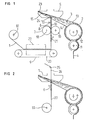
- FIG. 1 represents a device using a rotor, a member of false torsion and traction, and means of application of sticky material
- Figure 2 shows a device using a rotor, a false twist member and means for introducing a continuous filament.
- the spinning installation successively comprises, in the direction of production of the yarn 1, a device 2 intended to disperse the fibers 3 contained in a supply ribbon 4, a rotor 5, a member of false twist and traction 6, means 7 of traction and impregnation of an adhesive solution 8, means 9 for drying and winding means 10 for the wire 1 thus produced.
- the device 2 for dispersing the fibers 3 comprises, in a known manner, a feed roller II which takes up the fiber ribbon 4 and leads it to a breaker 12 placed in a chamber 13 which surrounds the breaker 12 and of which a part 14 collects the fibers 3 dissociated by the breaker 12 and directs them towards the inside of the rotor 5.
- This member 6 At the outlet of the rotor 5 and in the axis of rotation of the latter is placed the member 6 which ensures both the false twist and the traction of the wire 1.
- This member 6 consists of a rectilinear passage conduit 16 which the wire 1 crosses and which is traversed by a stream of helical air suitable for driving the wire 1 downstream of the conduit 16 and providing it with the twist.
- the formation of this helical air current is obtained by an inlet 17 of compressed air (connected to a source not shown) which is located in a plane parallel to the conduit 16, which opens tangentially with respect to said conduit 16 and that is tilted relative. 1 the direction of the con duit.
- Such a device is described in French patent application N0 81.24610.
- the means 7 of traction and impregnation of the glue solution 8 consist of two rollers 18 and 19 whose parallel axes are located in the plane perpendicular to the direction of travel of the wire 1 to the outlet of the conduit 16 from the member 6.
- the adhesive solution 8 is supplied to the roller 19 by any suitable means, either using an additional roller immersed in a tank containing said adhesive solution, or by direct feeding into the gap located above and between the two rollers 18 and 19.
- the adhesive solution 8 is of a composition adapted to the nature of the fibers constituting the wire 1; solutions containing a few percent (4 or 5%) of polyvinyl alcohol or acrylic copolymers are readily used.
- the drying means 9 comprise a mat 20 on which is deposited the wire 1 leaving the impregnation means 7.
- a complementary device 21 of traction possibly of the same type as the device 6 of false twist and pull.
- the actual drying is carried out thanks to an enclosure 22 supplied with hot air
- the operation of the installation is as follows.
- the constituent fibers of the ribbon 4 are brought by the feed roller 11 to the breaker 12, which dissociates the ribbon, individualizes the fibers 3 and projects them into the channel 14.
- the end 15 of the channel 14 emerging inside. from the rotor 5, the fibers 3 are collected in the groove 23 of the rotor 5 and the wire I thus formed leaves the rotor 5 through the nozzle 24 and passes through the passage duct 16 of the member 6 of false twist and traction.
- the additional torsion caused by the helical air current which crosses the duct 16 is added to that already acquired by the wire 1 thanks to the rotation of the rotor 5 and goes up to the inside of the rotor.
- the tension provided by the member 6 as well as by the means 7 of traction and impregnation allows the extraction of the wire 1 from the rotor 5.
- the wire 1 is impregnated with the glue solution 8, then is projected by the device? 1 on the mat 20 where it accumulates in the form of a regular sheet.
- the mat 20, which is a fine sad grid, made of teflon glass, is driven in a translational movement during which it passes through the drying oven 22 which is supplied by a current of hot air circulating inside said oven at the level of the mat 20.
- the solvent for the glue solution 8 s evaporates under the action of hot air, and the dried yarn 1 is finally received on a winder 10.
- the applications of such a thread relate inter alia to weft threads intended for scraped articles, sponge loop threads, hosiery, knitted weft inserts and in general all the applications where the threads obtained according to the rotor-free fibers technique cannot be used due to their excessive torsion.
- the yarn 1 obtained is applied even in the case of yarns having to undergo high stresses during manufacture, for example in warp yarn.
- FIG. 2 shows an installation according to the invention which comprises, opens the means 2 for dissociating the fibers and the rotor 5, means 24 for introducing a filament 26 into the rotor 5 along the axis of rotation thereof. ci and in such a way that the filament 24 leaves the rotor 5 in the same direction as the wire 1 formed in the rotor 5, then the member 6 of false twist and traction and winding means 10.
- the wire 1 formed in the rotor turns during its formation around the filament 24 and the wire 27, after passing through the member 6 is a wrapped wire.
- the invention is not limited to rotor spinning but applies to all spinning techniques in which all or part of the fibers are released and then recondensed in a means for taking torsion. It is spinning with released fibers proper, with as torsion taking means, either a rotor, as described above, or a friction device, for example two rollers of parallel axes, rotating in opposite directions, between which the fibers are projected; it is also about spinning with partially released fibers, with as a means of taking torsion for example air jets which give the outside fibers of the thread released relative to the core of the thread, a true twist in such a way that said fibers ensure the cohesion of the wire by a sort of bundle. In all these cases, thanks to the method and the device of the invention, the production speed can be increased appreciably.
Landscapes
- Engineering & Computer Science (AREA)
- Mechanical Engineering (AREA)
- Textile Engineering (AREA)
- Yarns And Mechanical Finishing Of Yarns Or Ropes (AREA)
- Spinning Or Twisting Of Yarns (AREA)
Applications Claiming Priority (2)
| Application Number | Priority Date | Filing Date | Title |
|---|---|---|---|
| FR8410280A FR2566810B1 (fr) | 1984-06-28 | 1984-06-28 | Procede et dispositif perfectionnes de filature du type a fibres liberees |
| FR8410280 | 1984-06-28 |
Publications (1)
| Publication Number | Publication Date |
|---|---|
| EP0167441A1 true EP0167441A1 (de) | 1986-01-08 |
Family
ID=9305584
Family Applications (1)
| Application Number | Title | Priority Date | Filing Date |
|---|---|---|---|
| EP85401231A Withdrawn EP0167441A1 (de) | 1984-06-28 | 1985-06-20 | Offen-End-Spinnverfahren und Vorrichtung |
Country Status (3)
| Country | Link |
|---|---|
| EP (1) | EP0167441A1 (de) |
| JP (1) | JPS6119823A (de) |
| FR (1) | FR2566810B1 (de) |
Cited By (4)
| Publication number | Priority date | Publication date | Assignee | Title |
|---|---|---|---|---|
| EP0279434A1 (de) * | 1987-02-20 | 1988-08-24 | W. SCHLAFHORST AG & CO. | Verfahren und Vorrichtung zum Verbessern eines in dem Rotor einer Offenend-Spinnvorrichtung erzeugten Garns |
| CN107794615A (zh) * | 2017-10-19 | 2018-03-13 | 江苏新芳科技集团股份有限公司 | 一种新型复合式包芯纱 |
| CN109402808A (zh) * | 2018-12-31 | 2019-03-01 | 郑州登电玄武石纤有限公司 | 一种玄武岩纤维并捻装置 |
| CN114411295A (zh) * | 2021-12-20 | 2022-04-29 | 东华大学 | 一种超细纤维/短纤转杯复合纱 |
Citations (5)
| Publication number | Priority date | Publication date | Assignee | Title |
|---|---|---|---|---|
| FR2081779A1 (de) * | 1970-03-09 | 1971-12-10 | Vyzk Ustav Bavlnarsky | |
| FR2203386A5 (en) * | 1972-10-16 | 1974-05-10 | Mulhouse Ste Const Meca | Open end spinning device having spinning rotor - to which a gimping yarn is fed to be twisted around the spun yarn produced in the rotor |
| FR2210684A1 (de) * | 1972-11-30 | 1974-07-12 | Sacm Alsacienne Const Mecaniqu | |
| DE2811329A1 (de) * | 1978-03-16 | 1979-09-20 | Krall & Roth Weberei Gmbh & Co | Verfahren zum herstellen und vorrichtung zum verzwirnen von komponenten eines zwirnes zum herstellen eines bielastischen gewebes |
| GB2017167A (en) * | 1978-03-28 | 1979-10-03 | Alsacienne Constr Meca | Method and devise for locally reducing the pitch of helices formed by the strands of a flexible twisted thread like product |
-
1984
- 1984-06-28 FR FR8410280A patent/FR2566810B1/fr not_active Expired
-
1985
- 1985-06-20 EP EP85401231A patent/EP0167441A1/de not_active Withdrawn
- 1985-06-28 JP JP14237285A patent/JPS6119823A/ja active Pending
Patent Citations (5)
| Publication number | Priority date | Publication date | Assignee | Title |
|---|---|---|---|---|
| FR2081779A1 (de) * | 1970-03-09 | 1971-12-10 | Vyzk Ustav Bavlnarsky | |
| FR2203386A5 (en) * | 1972-10-16 | 1974-05-10 | Mulhouse Ste Const Meca | Open end spinning device having spinning rotor - to which a gimping yarn is fed to be twisted around the spun yarn produced in the rotor |
| FR2210684A1 (de) * | 1972-11-30 | 1974-07-12 | Sacm Alsacienne Const Mecaniqu | |
| DE2811329A1 (de) * | 1978-03-16 | 1979-09-20 | Krall & Roth Weberei Gmbh & Co | Verfahren zum herstellen und vorrichtung zum verzwirnen von komponenten eines zwirnes zum herstellen eines bielastischen gewebes |
| GB2017167A (en) * | 1978-03-28 | 1979-10-03 | Alsacienne Constr Meca | Method and devise for locally reducing the pitch of helices formed by the strands of a flexible twisted thread like product |
Cited By (5)
| Publication number | Priority date | Publication date | Assignee | Title |
|---|---|---|---|---|
| EP0279434A1 (de) * | 1987-02-20 | 1988-08-24 | W. SCHLAFHORST AG & CO. | Verfahren und Vorrichtung zum Verbessern eines in dem Rotor einer Offenend-Spinnvorrichtung erzeugten Garns |
| CN107794615A (zh) * | 2017-10-19 | 2018-03-13 | 江苏新芳科技集团股份有限公司 | 一种新型复合式包芯纱 |
| CN109402808A (zh) * | 2018-12-31 | 2019-03-01 | 郑州登电玄武石纤有限公司 | 一种玄武岩纤维并捻装置 |
| CN109402808B (zh) * | 2018-12-31 | 2023-11-28 | 郑州登电玄武石纤有限公司 | 一种玄武岩纤维并捻装置 |
| CN114411295A (zh) * | 2021-12-20 | 2022-04-29 | 东华大学 | 一种超细纤维/短纤转杯复合纱 |
Also Published As
| Publication number | Publication date |
|---|---|
| FR2566810B1 (fr) | 1986-09-12 |
| JPS6119823A (ja) | 1986-01-28 |
| FR2566810A1 (fr) | 1986-01-03 |
Similar Documents
| Publication | Publication Date | Title |
|---|---|---|
| EP0085634B1 (de) | Verfahren und Einrichtung zur Herstellung eines Garns | |
| EP0085635B1 (de) | Verfahren und Vorrichtung zum Herstellen von Coregarn | |
| CH616967A5 (de) | ||
| FR2566810A1 (fr) | Procede et dispositif perfectionnes de filature du type a fibres liberees | |
| EP0098230B1 (de) | Verfahren und Vorrichtung zum Herstellen von Coregarn aus Fasern | |
| PL165034B1 (en) | Method and device for preparing the fibres for spinning | |
| FR2668176A1 (fr) | Structure filiforme guipee comprenant des fibres metalliques. | |
| EP0083897B1 (de) | Verfahren, Vorrichtung und Anlage zum Entfernen einer Faserlunte nach ihrer Nassbehandlung | |
| US1959142A (en) | Manufacture of yarns | |
| EP0745709A1 (de) | Flachfaserflocken und Aufbereitungsverfahren | |
| WO2001034892A1 (fr) | Procede et installation d'elaboration d'une nappe fibreuse multidirectionnelle | |
| FR2667618A1 (fr) | Procede pour l'obtention d'un file de fibres et dispositif pour sa mise en óoeuvre. | |
| EP0197851B1 (de) | Aus zwei Komponenten bestehender Nähfaden, hergestellt mittels einer Offen-End-Spinnvorrichtung | |
| CH572113A5 (en) | Spirally sheathed yarn of stable fibres without twist - core not fully covered, enclosed by uniformly spaced spirals(BR-23.12.75) | |
| BE521839A (de) | ||
| BE540261A (de) | ||
| EP0140796B1 (de) | Verfahren und Vorrichtung zum Beheben von Fadenbrüchen bei einem Umwindegarn | |
| CZ310139B6 (cs) | Způsob výroby lineárního nanovlákenného útvaru ve střídavém elektrickém poli, zařízení k provádění tohoto způsobu a zařízení k výrobě nanovlákenné niti | |
| CH333873A (fr) | Appareil pour la fabrication d'un fil mixte | |
| BE1002753A3 (fr) | Procede et dispositif pour l'alimentation d'au moins deux postes de metier continu a filer a anneaux au moyen d'une meche etiree. | |
| FR2520391A1 (en) | Prodn. of fibres-coated, multifilament thread for weaving etc. - contacts thread with fibres in circumferential channel of rotating guide wheel | |
| BE823788A (fr) | Procede et appareil pour produire du fil a tapis antistatique. | |
| EP0156739A1 (de) | Vorrichtung zur Herstellung von Spinngarn | |
| FR2749859A1 (fr) | Procede de realisation d'un fil mixte extensible et machine pour sa mise en oeuvre | |
| EP0137088A1 (de) | Verfahren und Vorrichtung zur Garntexturierung, insbesondere durch Falschdrehen |
Legal Events
| Date | Code | Title | Description |
|---|---|---|---|
| PUAI | Public reference made under article 153(3) epc to a published international application that has entered the european phase |
Free format text: ORIGINAL CODE: 0009012 |
|
| AK | Designated contracting states |
Designated state(s): BE CH DE FR GB IT LI NL |
|
| STAA | Information on the status of an ep patent application or granted ep patent |
Free format text: STATUS: THE APPLICATION IS DEEMED TO BE WITHDRAWN |
|
| 18D | Application deemed to be withdrawn |
Effective date: 19860909 |
|
| RIN1 | Information on inventor provided before grant (corrected) |
Inventor name: EXBRAYAT, PIERRE |