EP0167560B1 - Verfahren und vorrichtung zur trennung - Google Patents
Verfahren und vorrichtung zur trennung Download PDFInfo
- Publication number
- EP0167560B1 EP0167560B1 EP19850900251 EP85900251A EP0167560B1 EP 0167560 B1 EP0167560 B1 EP 0167560B1 EP 19850900251 EP19850900251 EP 19850900251 EP 85900251 A EP85900251 A EP 85900251A EP 0167560 B1 EP0167560 B1 EP 0167560B1
- Authority
- EP
- European Patent Office
- Prior art keywords
- screenings
- scraper
- grid
- scraper member
- movement
- Prior art date
- Legal status (The legal status is an assumption and is not a legal conclusion. Google has not performed a legal analysis and makes no representation as to the accuracy of the status listed.)
- Expired
Links
Images
Classifications
-
- E—FIXED CONSTRUCTIONS
- E02—HYDRAULIC ENGINEERING; FOUNDATIONS; SOIL SHIFTING
- E02B—HYDRAULIC ENGINEERING
- E02B8/00—Details of barrages or weirs ; Energy dissipating devices carried by lock or dry-dock gates
- E02B8/02—Sediment base gates; Sand sluices; Structures for retaining arresting waterborne material
- E02B8/023—Arresting devices for waterborne materials
- E02B8/026—Cleaning devices
Definitions
- the present invention relates to a method and an apparatus for separating, from a liquid flow, for example a flow of wastewater, solid pollutants and, more precisely, a method and an apparatus in which a screening grid traps pollutants from liquid passing through the grid and scraper devices clean the grid and remove pollutants trapped on the grid.
- Prior art mechanical separation devices for coarse solid pullutants consist of a screening grid comprising parallel bars between which there are formed gaps normally of a width of from 10 to 15 mm.
- the grid is disposed in a channel along which the polluted liquid flows, the location of the grid being such that the liquid is forced to flow through the gaps which the grid creates.
- the gaps are oriented substantially vertically and with the upper portion of the grid slightly offset in the direction of flow of the liquid.
- scraper rake
- the pollutants screening
- the scraper is fixed by means of arms to chain driven hoists which, in their upward movement, move the scraper from the lowermost edge of the grid to such a level above the surface of the liquid that the screenings may readily be taken care of, for example transferred to a receptacle or transported further by means of a conveyor.
- the scraper is, at its highest position, at least approximately 1.5 m above the surface of the liquid and, in its lowermost position, approximately 1 metre above the bottom of the channel.
- Prior art embodiments of screening grids with straight grid bars from which the screenings are separated by means of scrapers suffer from the drawback that they require tall building heights and, consequently, tall ceiling height, because of the length of travel of the scraper.
- the total length is determined by the depth of the liquid and requisite lifting height for the screenings above the surface of the liquid.
- prior art grid constructions are unwieldy and expensive. This latter circumstance is further accentuated by the fact that the construction should preferably be of stainless steel.
- the Patent Document DE-A-2 654 475 discloses an apparatus having the features of the precharacterising parts of the present claims 1 and 7.
- the construction of Rimmele relies on the use of a scraper which travels all the way from the bottom of the grid to the top of it in order to remove the screenings trapped by the grid bars and continues to travel towards the top of the apparatus in order to transfer the screenings to a receiving device.
- the construction suffers from the drawback of requiring tall building heights and tall ceiling heights because of the length of travel of the scraper.
- the present invention which relates to "machine-cleaned grids", substantially obviates the above-outlined drawbacks, since the total building height requirements of the installation may, in the great majority of cases, be reduced by approximately half in comparison with prior art equipment. This is effected by means of a reduction of the requisite movement space for the members which realise clean-scraping of screenings from the screen grid and movement of such screenings in a direction towards a receptacle facility. Moreover, it is possible, according to the present invention, to utilize more smoothly and evenly operating driving means than the previously-used electro-mechanical driving means which include an electric motor, gearing, one or more chain hoists and requisite journalling.
- An apparatus for separating solid pollutants from liquids includes, according to the present invention, a grid of the fundamentally conventional type as described above, i.e. a straight grid made up of parallel bars with substantially vertical orientation and a scraper member known from prior art, substantially in abutment against the bars of the screen grid and under movement, at least along a portion of the screen grid entraining screenings gathered against the grid, thereby raising these screenings out of the liquid passing through the grid.
- the apparatus includes at least one additional scraper member which in sequence shifts the screenings further towards, for example receptacle means.
- the additional scraper members are located above the first scraper member and move their scraper blades substantially along a residual section of the grid and/or, where applicable, along an extension section connected to the grid for continued transport of the screenings, e.g. to the receptacle means.
- the apparatus includes one or more shoulder-like regions located in the transition between two mutually adjacent scraper members.
- the first of the scraper members moves the screenings to one such shoulder-like region, and the other moves the screenings from the shoulder-like region.
- a corresponding cooperation takes place between the scraper members.
- the grid, the extension section of the transition between the grid and the extension section includes the shoulder-like regions.
- compression means are provided for compression of the screenings during their stay-time on each respective shoulder-like region, whereby the proportion of water in the screenings will be reduced.
- each respective scraper member is disposed to be reversible, there being formed an abutment surface which is urged by the scraper member against screenings located on each respective shoulder-like region.
- the scraper blades of the scraper members form the above-outlined compression means.
- each respective abutment surface is reversed prior to the. movement of the scraper member for moving the screenings into an orientation which is substantially at right angles to the direction of movement of each respective scraper blade during movement of the screenings.
- the abutment surface will thereby constitute that surface which shifts the screenings to subsequent transitional regions between two mutually adjacent scraper members.
- the lower scraper member completes more than one reciprocal movement between each such movement in which the remaining scraper members move the screenings in a direction towards a receptacle.
- the lower scraper member is disposed also on its downward movement to abut against the bars of the grid, at least along a restricted portion of this travel, this restricted travel being preferably located in a region at and slightly below the surface of the liquid.
- this restricted travel being preferably located in a region at and slightly below the surface of the liquid.
- each separate scraper member with a design which is particularly adapted to meet its purpose. This results in the realisation of an optimum function of each respective scraper member.
- the lower scraper member is designed with a view to transport by flowing liquid and to cleaning the gaps between the bars of the grid, while the scraper member or members operating above the surface of the liquid are designed in adaptation to meet, for example, the requirement of de-watering of the screenings and their further conveyance to receptacle means.
- the extension section disposed in association with the grid and preferably above the surface of the liquid is designed as a slip plane for cooperation with one or more scraper members.
- each such scraper member is operated by a separate prime mover, for example a compressed air cylinder which controls the position of the scraper blade in relation to the surface of the slip plane so that the scraper blade is located slightly above or, alternatively, abuts against the slip plane.
- a separate prime mover for example a compressed air cylinder which controls the position of the scraper blade in relation to the surface of the slip plane so that the scraper blade is located slightly above or, alternatively, abuts against the slip plane.
- the movement of the scraper members along the grid and, where applicable, along the extension section, is suitably realised by a joint prime mover, for instance a compressed air cylinder whose stroke length is adapted according to the longest individual scraping movement.
- a joint prime mover for instance a compressed air cylinder whose stroke length is adapted according to the longest individual scraping movement.
- Each one of the scraper members is preferably in cooperation with a sled-like device which is connected to the prime mover.
- a number of, or all of, the scraper members utilize one common such sled-like device, while, in other embodiments of the present invention, each scraper member is provided with its separate sled-like device.
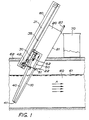
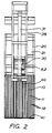
- the figures illustrate one embodiment of the invention in which the separation apparatus is composed of a lower portion which essentially comprises a grid 10, and an upper portion which essentially comprises an extension section 20. There is further disposed a first, lower scraper member 40, substantially for cooperation with the grid 10, and a second, upper scraper member 50, substantially for cooperation with the extension section 20.
- the grid 10 comprises a number of grid bars 11 forming gaps 12 therebetween. The distance between the grid bars is adapted to suit the size of the particles which are intended to be trapped by the grid bars on passage of the liquid through the grid.
- the grid merges into the extension section 20 which is shown on the drawings as including a slip plate 21 which forms a substantially downwardly directed supporting surface in a through-like part of the extension section 20.
- the slip plate forms a shoulder-like portion 22 which connects with the grid 10.
- the first, lower scraper member 40 is provided with a scraper blade 41 for cooperation with the grid 10 in certain embodiments, the blade is fitted with prong-like members which, when the blade abuts against the grid bars, penetrate into the space between the bars.
- An operating device 42 is fixedly retained in relation to a sled 30 and is connected to the first scraper member for adjustment of its distance, and thereby the distance of the scraper blade 41, to the grid bars 11.
- the second, upper scraper member 50 is, similarly, provided in its lower region with a scraper blade 51 for cooperation with the slip plate 21.
- An operating device 52 isfixedly retained in relation to the sled 30 and is connected to the second scraper member for adjustment of its distance, and thereby the distance of the scraper blade 51, to the supporting surface of the slip plate 21.
- switching means are provided for adjustment of an abutment surface on each respective scraper member to an orientation adapted to the orientation of the path in the area of each respective shoulder-like portion 22.
- the shoulder-like portion 22 is formed by the screen grid 10, by the screen grid 10 and the extension section 20 together or formed by the extension.
- a path 35 is provided for the sled 30 which, in its turn, is connected to driving means 31 which reciprocate the sled along the path 35.
- Fig 1 also showsthatthe grid 10 is immersed in a liquid 60 which flows in the direction indicated by the arrows A.
- Reference numeral 61 refers to the surface of the liquid.
- Figure 1 further intimates the presence of an outer casing 80 which covers the extension section 20.
- figure 1 also shows a receptacle 70 placed on a substrate, for example a floor 62, the receptacle receiving the screenings which are shifted by the second, upper scraper member 50 past the upper edge 23 of the extension section.
- the operating device 42 and the operating device 52 have been activated for moving the scraper members, and thereby the scraper blades 41, 51, to the positions illustrated in Fig. 1, i.e. to positions where the scraper blades abut against the grid bars 11 and against the slip plate 21, respectively. It is further assumed that the sled 30 and, thereby, the scraper members 40, 50, are in the positions illustrated in Fig. 1.
- the driving means 31 thereafter initiates the movement of the sled 30 upwardly in the drawings.
- the operating device 42 and the operating device 52 maintain the abutment of each respective scraper blade against the grid bars 11 and the slip plate 21, respectively, whereby both the screenings gathered against the grid bars and the screenings located on the shoulder-like portion 22 will be shifted in a direction towards the receptacle 70.
- the driving means 31 subsequently reciprocates the sled 30 to its starting position.
- the scraper blades are, as a rule, raised from the grid bars and the slip plate 21, respectively, for a pre-determined and pre-set length of the movement.
- the length of the extension section 20 and the grid 10 are mutually adapted and adapted to the stroke length of the driving means 31 of the sled so that, during the final phase of the movement of the sled, screenings from the grid 10 will be deposited on the shoulder-like portion 22, atth-e same time as the screenings which the second, upper scraper 50 just previously removed from the shoulder-like portion will be reliably and safely deposited - or will have already been deposited - in the recep- ta.cle 70.
- the scraper blade cleans the gaps between the grid bars in that the prong-like members of the scraper blade are passed in the spaces between the bars.
- more than one sled is employed for movement of the scraper members, while in certain physical applications, each sled is combined with a separate prime moverfortransport of the sled. For example, it is thereby possible to cause the lower scraper memberto execute more than one upward movement for shifting of screenings to the shoulder-like portion before the screenings are conveyed to the receptacle.
Landscapes
- Engineering & Computer Science (AREA)
- General Engineering & Computer Science (AREA)
- Mechanical Engineering (AREA)
- Civil Engineering (AREA)
- Structural Engineering (AREA)
- Separation Of Solids By Using Liquids Or Pneumatic Power (AREA)
- Chain Conveyers (AREA)
- Filtration Of Liquid (AREA)
Claims (10)
Priority Applications (1)
| Application Number | Priority Date | Filing Date | Title |
|---|---|---|---|
| AT85900251T ATE33948T1 (de) | 1983-12-27 | 1984-12-19 | Verfahren und vorrichtung zur trennung. |
Applications Claiming Priority (2)
| Application Number | Priority Date | Filing Date | Title |
|---|---|---|---|
| SE8307171A SE440029B (sv) | 1983-12-27 | 1983-12-27 | Avskiljningsanordning |
| SE8307171 | 1983-12-27 |
Publications (2)
| Publication Number | Publication Date |
|---|---|
| EP0167560A1 EP0167560A1 (de) | 1986-01-15 |
| EP0167560B1 true EP0167560B1 (de) | 1988-05-04 |
Family
ID=20353896
Family Applications (1)
| Application Number | Title | Priority Date | Filing Date |
|---|---|---|---|
| EP19850900251 Expired EP0167560B1 (de) | 1983-12-27 | 1984-12-19 | Verfahren und vorrichtung zur trennung |
Country Status (4)
| Country | Link |
|---|---|
| EP (1) | EP0167560B1 (de) |
| DE (1) | DE3470851D1 (de) |
| SE (1) | SE440029B (de) |
| WO (1) | WO1985002794A1 (de) |
Families Citing this family (1)
| Publication number | Priority date | Publication date | Assignee | Title |
|---|---|---|---|---|
| NZ513378A (en) * | 2001-08-07 | 2004-03-26 | Power Glides Screens Ltd | Suspension screen raking system with spaced longitudinal rakes reciprocating for reduced ltravel |
Family Cites Families (4)
| Publication number | Priority date | Publication date | Assignee | Title |
|---|---|---|---|---|
| DE1048836B (de) * | 1957-06-25 | 1959-01-15 | Voith Gmbh J M | Rechenreinigungsmaschine, insbesondere fuer Einlaufrechen von Wasserkraftmaschinen |
| SE309391B (de) * | 1967-03-28 | 1969-03-17 | Tolu Ab | |
| CH600060A5 (de) * | 1975-12-11 | 1978-06-15 | Mecafina Sa | |
| DE2629603C3 (de) * | 1976-07-01 | 1979-11-08 | Dambach-Industrieanlagen Gmbh, 7560 Gaggenau | Rechenreiniger mit Rechenharke |
-
1983
- 1983-12-27 SE SE8307171A patent/SE440029B/sv not_active IP Right Cessation
-
1984
- 1984-12-19 WO PCT/SE1984/000434 patent/WO1985002794A1/en not_active Ceased
- 1984-12-19 EP EP19850900251 patent/EP0167560B1/de not_active Expired
- 1984-12-19 DE DE8585900251T patent/DE3470851D1/de not_active Expired
Also Published As
| Publication number | Publication date |
|---|---|
| SE440029B (sv) | 1985-07-15 |
| EP0167560A1 (de) | 1986-01-15 |
| SE8307171D0 (sv) | 1983-12-27 |
| DE3470851D1 (en) | 1988-06-09 |
| SE8307171L (sv) | 1985-06-28 |
| WO1985002794A1 (en) | 1985-07-04 |
Similar Documents
| Publication | Publication Date | Title |
|---|---|---|
| WO1999066141A1 (en) | A screening apparatus | |
| EP0098820A2 (de) | Vorrichtung geeignet zum Sammeln und Aufheben von Feststoffen | |
| KR101887831B1 (ko) | 협잡물 퇴적방지구조가 적용된 계단식 여과기 | |
| US5779887A (en) | Gravity screen with burden removal and pore-cleaning means | |
| EP0346311B1 (de) | Rechen | |
| EP0071442A2 (de) | Filtervorrichtung | |
| US4289619A (en) | Material handling apparatus | |
| WO1998030311A9 (en) | Gravity screen with burden removal and pore-cleaning means | |
| CN1052285C (zh) | 将格栅截留物从巨大水量中清出的装置 | |
| EP0167560B1 (de) | Verfahren und vorrichtung zur trennung | |
| KR101254450B1 (ko) | 대형 협잡물 제거용 스크린 제진기 | |
| EP0954651B1 (de) | Geneigter abwasserrechen | |
| US2963156A (en) | Method of and apparatus for cleaning screens | |
| RU2004106553A (ru) | Скребковая система чистки мусорозадерживающей решетки для очистки суспензий | |
| KR102701753B1 (ko) | 하폐수용 협잡물 처리장치 | |
| EP0738354B1 (de) | Verfahren und vorrichtung zum behandeln von abwasser | |
| JPH08912A (ja) | 沈澱分離装置 | |
| CN214019460U (zh) | 一种环保工程用污水固液分离器 | |
| EP1285142B1 (de) | Selbstreinigende vorrichtung, insbesondere für abwasserrechen | |
| KR100376766B1 (ko) | 조대 협잡물 제거장치 | |
| KR102701751B1 (ko) | 하폐수용 수직 협잡물 제거장치 | |
| RU2059050C1 (ru) | Устройство для очистки от твердых включений потока сточных вод в каналах | |
| CN219885753U (zh) | 一种油污处理装置 | |
| KR20000015419U (ko) | 오,폐수에 함유된 슬러지 제거 장치 | |
| KR200265556Y1 (ko) | 배수처리용 협잡물 처리장치 |
Legal Events
| Date | Code | Title | Description |
|---|---|---|---|
| PUAI | Public reference made under article 153(3) epc to a published international application that has entered the european phase |
Free format text: ORIGINAL CODE: 0009012 |
|
| 17P | Request for examination filed |
Effective date: 19850813 |
|
| AK | Designated contracting states |
Designated state(s): AT BE CH DE FR GB LI LU NL SE |
|
| 17Q | First examination report despatched |
Effective date: 19860922 |
|
| GRAA | (expected) grant |
Free format text: ORIGINAL CODE: 0009210 |
|
| AK | Designated contracting states |
Kind code of ref document: B1 Designated state(s): AT BE CH DE FR GB LI LU NL SE |
|
| PG25 | Lapsed in a contracting state [announced via postgrant information from national office to epo] |
Ref country code: BE Effective date: 19880504 |
|
| REF | Corresponds to: |
Ref document number: 33948 Country of ref document: AT Date of ref document: 19880515 Kind code of ref document: T |
|
| PG25 | Lapsed in a contracting state [announced via postgrant information from national office to epo] |
Ref country code: SE Effective date: 19880531 |
|
| REF | Corresponds to: |
Ref document number: 3470851 Country of ref document: DE Date of ref document: 19880609 |
|
| RAP2 | Party data changed (patent owner data changed or rights of a patent transferred) |
Owner name: SPIRAC ENGINEERING AB |
|
| ET | Fr: translation filed | ||
| PG25 | Lapsed in a contracting state [announced via postgrant information from national office to epo] |
Ref country code: LU Free format text: LAPSE BECAUSE OF NON-PAYMENT OF DUE FEES Effective date: 19881231 |
|
| PLBE | No opposition filed within time limit |
Free format text: ORIGINAL CODE: 0009261 |
|
| STAA | Information on the status of an ep patent application or granted ep patent |
Free format text: STATUS: NO OPPOSITION FILED WITHIN TIME LIMIT |
|
| 26N | No opposition filed | ||
| PGFP | Annual fee paid to national office [announced via postgrant information from national office to epo] |
Ref country code: CH Payment date: 19911128 Year of fee payment: 8 |
|
| PGFP | Annual fee paid to national office [announced via postgrant information from national office to epo] |
Ref country code: FR Payment date: 19911129 Year of fee payment: 8 Ref country code: AT Payment date: 19911129 Year of fee payment: 8 |
|
| PGFP | Annual fee paid to national office [announced via postgrant information from national office to epo] |
Ref country code: GB Payment date: 19911206 Year of fee payment: 8 |
|
| PGFP | Annual fee paid to national office [announced via postgrant information from national office to epo] |
Ref country code: NL Payment date: 19911231 Year of fee payment: 8 |
|
| PGFP | Annual fee paid to national office [announced via postgrant information from national office to epo] |
Ref country code: DE Payment date: 19920226 Year of fee payment: 8 |
|
| PG25 | Lapsed in a contracting state [announced via postgrant information from national office to epo] |
Ref country code: GB Effective date: 19921219 Ref country code: AT Effective date: 19921219 |
|
| PG25 | Lapsed in a contracting state [announced via postgrant information from national office to epo] |
Ref country code: LI Effective date: 19921231 Ref country code: CH Effective date: 19921231 |
|
| PG25 | Lapsed in a contracting state [announced via postgrant information from national office to epo] |
Ref country code: NL Effective date: 19930701 |
|
| NLV4 | Nl: lapsed or anulled due to non-payment of the annual fee | ||
| GBPC | Gb: european patent ceased through non-payment of renewal fee |
Effective date: 19921219 |
|
| PG25 | Lapsed in a contracting state [announced via postgrant information from national office to epo] |
Ref country code: FR Effective date: 19930831 |
|
| REG | Reference to a national code |
Ref country code: CH Ref legal event code: PL |
|
| PG25 | Lapsed in a contracting state [announced via postgrant information from national office to epo] |
Ref country code: DE Effective date: 19930901 |
|
| REG | Reference to a national code |
Ref country code: FR Ref legal event code: ST |