EP0167636B1 - Dispositif interrupteur à clef du type à auto-rétention - Google Patents
Dispositif interrupteur à clef du type à auto-rétention Download PDFInfo
- Publication number
- EP0167636B1 EP0167636B1 EP19840105010 EP84105010A EP0167636B1 EP 0167636 B1 EP0167636 B1 EP 0167636B1 EP 19840105010 EP19840105010 EP 19840105010 EP 84105010 A EP84105010 A EP 84105010A EP 0167636 B1 EP0167636 B1 EP 0167636B1
- Authority
- EP
- European Patent Office
- Prior art keywords
- cam
- key
- switch
- cylinder
- peripheral side
- Prior art date
- Legal status (The legal status is an assumption and is not a legal conclusion. Google has not performed a legal analysis and makes no representation as to the accuracy of the status listed.)
- Expired
Links
Images
Classifications
-
- H—ELECTRICITY
- H01—ELECTRIC ELEMENTS
- H01H—ELECTRIC SWITCHES; RELAYS; SELECTORS; EMERGENCY PROTECTIVE DEVICES
- H01H19/00—Switches operated by an operating part which is rotatable about a longitudinal axis thereof and which is acted upon directly by a solid body external to the switch, e.g. by a hand
- H01H19/02—Details
- H01H19/10—Movable parts; Contacts mounted thereon
- H01H19/28—Driving mechanisms allowing angular displacement of the operating part to be effective or possible in only one direction
-
- H—ELECTRICITY
- H01—ELECTRIC ELEMENTS
- H01H—ELECTRIC SWITCHES; RELAYS; SELECTORS; EMERGENCY PROTECTIVE DEVICES
- H01H27/00—Switches operated by a removable member, e.g. key, plug or plate; Switches operated by setting members according to a single predetermined combination out of several possible settings
- H01H27/06—Key inserted and then turned to effect operation of the switch
Definitions
- the invention relates to a self-holding key switch, wherein a switch is combined with a lock adapted to be released by inserting a key and the switch is turned on or off by rotating the inserted key.
- a rotor or rotatable cylinder of a lock main body is rotated by means of a key inserted into the cylinder, and a microswitch fitted to the rear of the lock main body is turned on and off by a cylindrical cam that rotates integrally with the cylinder.
- the cylinder and the cam being freely rotatable in both directions by means of the key, accidental or unintentional rotation of the inserted key by an operator can lead to the switch being turned on or off, there being no necessity of rotating the key up to 360° in order to turn of the switch.
- the switch can return to the off state easily within a short period of time.
- the document DE-B-1 131 464 describes a key-operated combined ignition and starter switch for an engine of a motor vehicle, the switch having the features described in the prior art portion of claim 1. Insertion of a key into a cylinder lock and rotation of the key in one direction brings a rotary switch from an off position into an ignition position and then into an engine starting position, at which stage a spring mechanism rotates the cylinder in the reverse direction to bring the switch back to the ignition position.
- a separate ratchet mechanism In order to prevent the switch from being inadvertently rotated a second time to the starting position before being first returned to the off position, a separate ratchet mechanism is provided, wherein two cam discs are fitted coaxially onto a rear extension of the lock cylinder, the rear cam disc being rotated integrally with the cylinder and the front cam disc being free to rotate with respect to the cylinder and the rear cam disc within a limited angular range.
- two spring-loaded pawls pivotally supported at the lock main body, each engage with one of two slight recesses formed on opposite perimeter portions of the front cam disc.
- Rotation of the cylinder to the ignition and engine starting positions first allows only the rear cam disc to rotate, whereafter the front cam disc is constrained to rotate in the same direction, the pawls being slid out of the slight recesses and then dropping into cutout portions of the perimeter of the front cam disc to abut against the perimeter of the rear cam disc.
- the subsequent spring-urged return of the cylinder to the ignition position causes the rear cam disc to rotate and one of the pawls to engage immediately with a tooth of the rear cam disc, so as to block a return of the cylinder to the starting position.
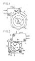
- the invention resides in that a pawl 6 is disposed sideways of a switch operating cam 5 for a switch 2 and is urged to rotate towards the peripheral side surface 5a of the cam 5, and a tooth 7 for meshing with the tip of the pawl 6 is disposed on the peripheral side surface 5a of the cam 5, so that reverse rotation of the cam 5 is prevented by the engagement of the pawl 6 with the tooth 7 when the switch 2 is turned on by rotation of the cam 5 in the normal operating direction.
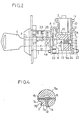
- a fitting base plate 8 is fixedly mounted to the rear of a lock main body 1 by a screw 9, and the microswitch type switch 2 is fixed to the fitting base plate 8 by a rear seat plate 10 in cooperation with a nut 11.
- the front end portion of an interlocking plate 13 is slidably inserted into the rear end portion of a key groove 12 formed in a lock cylinder 3 in its axial direction, and the rear - end portion of this interlocking plate 13 is fitted into a split groove 14 of the cylindrical cam 5 that extends in the radial direction of the cam 5.
- the rear end portion of the interlocking plate 13 is fixed to the cam 5 by a spring pin 15.
- a compression spring 17 and a small ball 18 are disposed in a centre through-hole 16 of the cam 5.
- the front end portion of the compression spring is in pressure contact with the interlocking plate 13, and the small ball 18 is in pressure contact with a receiving hole 19 that is disposed on the rear seat plate 10. Accordingly, the cam 5 is urged to slide towards the rear surface of the lock main body 1.
- the switch 2 is adapted to be turned on and off by engagement with the suitably formed peripheral side surface 5a of the cam 5.
- a step portion 21 is formed into which an actuator 20 of the switch 2 fits.
- the switch 2 is kept off.
- the tooth 7 described above is formed at a portion of the peripheral side surface 5a of the cam 5 with which the actuator 20 does not come into sliding contact, that is, at the front end portion of the peripheral side surface 5a of the cam 5.
- the base end portion of the pawl 6 is rotatably fitted to a bolt 22 which is interposed between the fitting base plate 8 and the rear seat plate 10.
- One of the ends of the pawl 6 is thus anchored to the fitting base plate 8, with the other being urged to rotate towards the peripheral side surface 5a of the cam 5 by a twist coil spring 23 which is in contact with a side surface at the tip of the pawl 6.
- a spacer cylinder 24 is fitted onto the portion of the bolt 22 between the pawl 6 and the rear seat plate 10. Locking of the cylinder 3 to the lock main body 1 is effected by use of a known disc tumbler mechanism, pin tumbler mechanism, or the like. This embodiment employs the pin tumbler mechanism.
- a follower pin 27 and a driving pin 28 disposed in pin receiving holes 25, 26 in the radial direction of the cylinder 3 and the lock main body 1, respectively, are urged to slide by a compression spring 29 in the axial direction of the cylinder 3.
- the present invention guides or forces the operator to fully rotate the cam 5 to 360° because of a ratchet mechanism that includes the pawl 6 and the tooth 7.
- the switch 2 is reliably kept in the ON state from the position P 1 to the position P 2 in Figure 1 for a predetermined period of time required for equipment with which the key switch is used.
Landscapes
- Lock And Its Accessories (AREA)
- Mechanisms For Operating Contacts (AREA)
Claims (3)
caractérisé en ce que
Priority Applications (2)
| Application Number | Priority Date | Filing Date | Title |
|---|---|---|---|
| EP19840105010 EP0167636B1 (fr) | 1984-05-04 | 1984-05-04 | Dispositif interrupteur à clef du type à auto-rétention |
| DE8484105010T DE3467464D1 (en) | 1984-05-04 | 1984-05-04 | Self-holding type key switch device |
Applications Claiming Priority (1)
| Application Number | Priority Date | Filing Date | Title |
|---|---|---|---|
| EP19840105010 EP0167636B1 (fr) | 1984-05-04 | 1984-05-04 | Dispositif interrupteur à clef du type à auto-rétention |
Publications (2)
| Publication Number | Publication Date |
|---|---|
| EP0167636A1 EP0167636A1 (fr) | 1986-01-15 |
| EP0167636B1 true EP0167636B1 (fr) | 1987-11-11 |
Family
ID=8191921
Family Applications (1)
| Application Number | Title | Priority Date | Filing Date |
|---|---|---|---|
| EP19840105010 Expired EP0167636B1 (fr) | 1984-05-04 | 1984-05-04 | Dispositif interrupteur à clef du type à auto-rétention |
Country Status (2)
| Country | Link |
|---|---|
| EP (1) | EP0167636B1 (fr) |
| DE (1) | DE3467464D1 (fr) |
Families Citing this family (2)
| Publication number | Priority date | Publication date | Assignee | Title |
|---|---|---|---|---|
| GB9121191D0 (en) * | 1991-10-05 | 1991-11-20 | Garner John G | Lockable electric socket |
| CN115719687A (zh) * | 2022-12-05 | 2023-02-28 | 中车株洲电力机车有限公司 | 一种模块化机车司机控制器电钥匙机构 |
Family Cites Families (5)
| Publication number | Priority date | Publication date | Assignee | Title |
|---|---|---|---|---|
| DE1131465B (de) * | 1960-07-09 | 1962-06-14 | Leopold Kostal Elektrotechn Sp | Vereinigter Zuend- und Anlassschalter |
| DE1240160B (de) * | 1964-07-27 | 1967-05-11 | Anders Elektronic G M B H | Mehrfachbetaetigungseinrichtung |
| DE2208019C3 (de) * | 1972-02-21 | 1974-09-19 | Fritz Richard 5021 Esch Baumgart | Schlüsselschalter |
| DE2403995A1 (de) * | 1974-01-29 | 1975-08-07 | Fritz Richard Baumgart | Schluesselschalter |
| JPS56130041A (en) * | 1980-03-15 | 1981-10-12 | Matsushita Electric Works Ltd | Relay driving circuit |
-
1984
- 1984-05-04 DE DE8484105010T patent/DE3467464D1/de not_active Expired
- 1984-05-04 EP EP19840105010 patent/EP0167636B1/fr not_active Expired
Also Published As
| Publication number | Publication date |
|---|---|
| EP0167636A1 (fr) | 1986-01-15 |
| DE3467464D1 (en) | 1987-12-17 |
Similar Documents
| Publication | Publication Date | Title |
|---|---|---|
| US5615564A (en) | Door locking device with an antitheft mechanism | |
| DE3314072C2 (de) | Schloßsystem zur mechanischen und elektronischen Steuerung von Verriegelungen in einem Kraftfahrzeug | |
| US5907963A (en) | Lock assembly with a key-activated removable core structure | |
| CN1145996C (zh) | 用于容放及固持一种识别信息发送器如电子钥匙的装置 | |
| JPH01315569A (ja) | ロック | |
| GB2278396A (en) | Vehicle door locking device with an antitheft mechanism | |
| JP2000203387A (ja) | 自動車のステアリングコラムに取り付ける盗難防止装置 | |
| CN1075588C (zh) | 一种带闭锁圆柱的锁定装置 | |
| JPS58145546A (ja) | 自動車用ステアリングロツク装置 | |
| DE10224657A1 (de) | Lenkradsperrvorrichtung | |
| EP0336219B1 (fr) | Dispositif de verrouillage de direction | |
| US7065993B2 (en) | Motor-driven steering lock device | |
| EP0423229A1 (fr) | Serrure de vehicule commandee par un levier de vitesses et procede | |
| JPS6015546B2 (ja) | 錠付き燃料キヤツプ | |
| EP0160715B1 (fr) | Dispositif de commutateur à clé amovible à pression rotative | |
| US4148201A (en) | Locking device | |
| GB2138067A (en) | Steering column lock | |
| US4333325A (en) | Steering shaft locking device | |
| US5794469A (en) | Steering lock device | |
| GB2284635A (en) | Vehicle door locking device with an antitheft mechanism | |
| JP2707347B2 (ja) | 施錠装置 | |
| EP0167636A1 (fr) | Dispositif interrupteur à clef du type à auto-rétention | |
| US7673483B2 (en) | Anti-theft device for a motor vehicle, such as an electronic anti-theft device | |
| JPS6231949Y2 (fr) | ||
| EP0143087A1 (fr) | Dispositif pour ouvrir ou fermer le coffre à bagages ou hayon arrière d'un véhicule automobile |
Legal Events
| Date | Code | Title | Description |
|---|---|---|---|
| PUAI | Public reference made under article 153(3) epc to a published international application that has entered the european phase |
Free format text: ORIGINAL CODE: 0009012 |
|
| AK | Designated contracting states |
Designated state(s): AT BE CH DE FR GB IT LI LU NL SE |
|
| 17P | Request for examination filed |
Effective date: 19860130 |
|
| 17Q | First examination report despatched |
Effective date: 19860919 |
|
| ITF | It: translation for a ep patent filed | ||
| GRAA | (expected) grant |
Free format text: ORIGINAL CODE: 0009210 |
|
| AK | Designated contracting states |
Kind code of ref document: B1 Designated state(s): DE FR GB |
|
| ET | Fr: translation filed | ||
| REF | Corresponds to: |
Ref document number: 3467464 Country of ref document: DE Date of ref document: 19871217 |
|
| PLBE | No opposition filed within time limit |
Free format text: ORIGINAL CODE: 0009261 |
|
| STAA | Information on the status of an ep patent application or granted ep patent |
Free format text: STATUS: NO OPPOSITION FILED WITHIN TIME LIMIT |
|
| 26N | No opposition filed | ||
| PGFP | Annual fee paid to national office [announced via postgrant information from national office to epo] |
Ref country code: GB Payment date: 19920424 Year of fee payment: 9 |
|
| PGFP | Annual fee paid to national office [announced via postgrant information from national office to epo] |
Ref country code: FR Payment date: 19920514 Year of fee payment: 9 |
|
| PGFP | Annual fee paid to national office [announced via postgrant information from national office to epo] |
Ref country code: DE Payment date: 19920730 Year of fee payment: 9 |
|
| PG25 | Lapsed in a contracting state [announced via postgrant information from national office to epo] |
Ref country code: GB Effective date: 19930504 |
|
| GBPC | Gb: european patent ceased through non-payment of renewal fee |
Effective date: 19930504 |
|
| PG25 | Lapsed in a contracting state [announced via postgrant information from national office to epo] |
Ref country code: FR Effective date: 19940131 |
|
| PG25 | Lapsed in a contracting state [announced via postgrant information from national office to epo] |
Ref country code: DE Effective date: 19940201 |
|
| REG | Reference to a national code |
Ref country code: FR Ref legal event code: ST |