EP0167667B1 - Gekapseltes elektrisches Schaltfeld - Google Patents
Gekapseltes elektrisches Schaltfeld Download PDFInfo
- Publication number
- EP0167667B1 EP0167667B1 EP84114394A EP84114394A EP0167667B1 EP 0167667 B1 EP0167667 B1 EP 0167667B1 EP 84114394 A EP84114394 A EP 84114394A EP 84114394 A EP84114394 A EP 84114394A EP 0167667 B1 EP0167667 B1 EP 0167667B1
- Authority
- EP
- European Patent Office
- Prior art keywords
- switch panel
- plug
- unit
- recess
- pull lever
- Prior art date
- Legal status (The legal status is an assumption and is not a legal conclusion. Google has not performed a legal analysis and makes no representation as to the accuracy of the status listed.)
- Expired
Links
Images
Classifications
-
- H—ELECTRICITY
- H02—GENERATION; CONVERSION OR DISTRIBUTION OF ELECTRIC POWER
- H02B—BOARDS, SUBSTATIONS OR SWITCHING ARRANGEMENTS FOR THE SUPPLY OR DISTRIBUTION OF ELECTRIC POWER
- H02B11/00—Switchgear having carriage withdrawable for isolation
- H02B11/12—Switchgear having carriage withdrawable for isolation with isolation by horizontal withdrawal
- H02B11/127—Withdrawal mechanism
- H02B11/133—Withdrawal mechanism with interlock
-
- H—ELECTRICITY
- H05—ELECTRIC TECHNIQUES NOT OTHERWISE PROVIDED FOR
- H05K—PRINTED CIRCUITS; CASINGS OR CONSTRUCTIONAL DETAILS OF ELECTRIC APPARATUS; MANUFACTURE OF ASSEMBLAGES OF ELECTRICAL COMPONENTS
- H05K7/00—Constructional details common to different types of electric apparatus
- H05K7/14—Mounting supporting structure in casing or on frame or rack
- H05K7/1401—Mounting supporting structure in casing or on frame or rack comprising clamping or extracting means
- H05K7/1411—Mounting supporting structure in casing or on frame or rack comprising clamping or extracting means for securing or extracting box-type drawers
Definitions
- the invention relates to an encapsulated electrical panel according to the preamble of claim 1.
- the object of the invention is to design the encapsulated electrical control panel of the preamble of claim 1 in a particularly simple manner so that the retractable lever can only be moved when the plug elements and mating plug elements can be safely connected or separated from one another.
- the training should also be such that the possibility of separating the plug-in elements and the mating plug-in elements can be recognized by the position of the pull-in lever.
- the object is achieved according to the invention by the training specified in the characterizing part of claim 1.
- 1 denotes an insert of an encapsulated electrical switch panel (not shown) with the exception of a switch panel rail 2 and a switch panel door 8.
- the insert 1 carries in the usual manner on its rear front, which cannot be seen from the drawing, plug-in elements for mating plug-in elements arranged in the control panel.
- the insert 1 carries a pull-in lever 4 which can be pivoted about a horizontal axis 3 and which on the one hand has the axis 3 a power arm 4a which can be retracted and returned from the front of the insert 1.
- the load arm 4b can be brought into engagement with a recess 5 of the switchgear rail 2.
- the recess 5 shows a front boundary edge 5a and a rear boundary edge 5b.
- the insertion of the insert into the panel is carried out in the reverse manner, with the difference that the load arm 4b of the lever 4 does not act on the rear boundary edge 5b but on the front boundary edge 5a of the recess 5 of the panel rail 2.
- the insert 1 is equipped with a rotary switch 6, the handle 6a of which lies in the insert front.
- the force arm 4a of the pull-in lever 4 can be blocked by a bolt 7 which, when the rotary switch 6 is switched on, can be moved into the pivoting path of the force arm 4a of the pull-in lever 4 is (Fig.1).
- the bolt 7 is attached directly to the switch axis, not shown. In a manner not shown, however, a gear can be provided between the switch axis and the bolt 7, with which a movement of the switch axis can be transmitted to the bolt 7.
- the power arm 4a of the pull-in lever 4 is designed such that it can be freely pivoted out of the insertion front after being released by the bolt 7 solely by its own weight until the load arm 4b rests on the rear boundary edge 5b of the recess 5 of the switchgear rail.
- the power arm 4a is pivoted out, it is immediately apparent that the rotary switch 6 is switched off in the operating position of the insert 1. So that the dead weight of the power arm 4a of the pull-in lever 4 comes into effect in the manner described, the center of gravity of the power arm 4a lies in front of the axis 3.
- the panel door 8 shown in the example shown is arranged so that it holds the retracting lever 4 in the insertion front when the rotary switch 6 is turned off.
- the power arm 4a of the pull-in lever 4 falls out of the front of the insert and thus indicates that the rotary switch 6 is switched off and the insert 1 can be moved from its operating position.
- the force arm 4a of the pull-in lever 4 can also be pivoted back into the insertion front when the rotary switch 6 is switched off.
- the panel door 8 cannot be closed, since the force arm 4a of the pull-in lever 4 lies in its pivoting-back path.
- a viewing window is expediently arranged in the control panel door 8, through which the position of the bolt 7 can be recognized when the door 8 is closed and the rotary switch 6 is switched on.
- the free end of the bolt 7 is expediently red for better visibility.
Landscapes
- Engineering & Computer Science (AREA)
- Power Engineering (AREA)
- Microelectronics & Electronic Packaging (AREA)
- Patch Boards (AREA)
- Mechanisms For Operating Contacts (AREA)
Description
- Die Erfindung bezieht sich auf ein gekapseltes elektrisches Schaltfeld nach dem Oberbegriff des Anspruches 1.
- Es ist bereits ein elektrisches Schaltfeld der im Oberbegriff des Anspruches 1 genannten Art bekannt. Aus dem bekannten Schaltfeld sind jedoch keine Maßnahmen nahegelegt, wie eine Bewegung des Einziehhebels verhinderbar ist, wenn die Steckelemente und die Gegensteckelemente aus Grüden der elektrischen Sicherheit auf keinen Fall entweder nicht voneinander getrennt oder nicht miteinander verbunden werden dürfen (DE-U-17 34 677).=
- Es ist auch bereits ein Schaltschrank bekannt, bei dem ein Einschub einen Drehschalter mit einem Triebstock trägt, mit dem ein auf dem Einschub befindlicher zweiarmiger Verriegelungshebel in Schaltrichtung "Aus" in eine das freie Verschieben des Einschubes gestattende Lage und in Schaltrichtung "Ein" in einen Verriegelungseingriff mit einem ortsfesten Schaltschrankelement bewegbar ist (DE-C-30 15 259).
- Aufgabe der Erfindung ist es, das gekapselte elektrische Schaltfeld der Gattung des Oberbegriffes des Anspruches 1 auf besonders einfache Weise so auszubilden, daß der Einziehhebel nur bewegbar ist, wenn die Steckelemente und Gegensteckelemente gefahrlos miteinander verbunden oder voneinander getrennt werden können. Die Ausbildung soll ferner so sein, daß die Möglichkeit des Trenners der Steckelemente und der Gegensteckelemente an der Stellung des Einziehhebels erkennbar ist.
- Die gestellte Aufgabe wird erfindungsgemäß durch die im kennzeichnenden Teil des Anspruches 1 angegebene Ausbildung gelöst.
- Zweckmäßige Aus- und Weiterbildungen des Erfindungsgegenstandes sind in den Ansprüchen 2 bis 5 angegeben.
- Ein Ausführungsbeispiel der Erfindung ist in der Zeichnung rein schematisch gezeigt. Es zeigen:
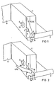
- Fig. 1 in perspektivischer Darstellung einen Einschub mit einem in die Einschubfront eingeschwenkten Einziehhebel,
- Fig. 2 eine perspektivische Darstellung wie in Fig. 1, jedoch mit ausgeschwenktem Einziehhebel.
- In der Zeichnung ist mit 1 ein Einschub eines mit Ausnahme einer Schaltfeldschiene 2 und einer Schaltfeldtür 8 im übrigen nicht dargestellten gekapselten elektrischen Schaltfeldes bezeichnet.
- Der Einschub 1 trägt in üblicher Weise auf seiner aus der Zeichnung nicht ersichtlichen Rückfront Steckelemente für im Schaltfeld angeordnete Gegensteckelemente.
- Ferner trägt der Einschub 1 einen um eine horizontale Achse 3 schwenkbaren Einziehhebel 4, der einerseits der Achse 3 einen aus der Front des Einschubes 1 heraus- und zurückschenkbaren Kraftarm 4a aufweist.
- Andererseits der Achse 3 befindet sich ein Lastarm 4b des Hebels 4. Der Lastarm 4b ist mit einer Ausnehmung 5 der Schaltfeldschiene 2 in Eingriff bringbar. Die Ausnehmung 5 zeigt eine vordere Begrenzungskante 5a und eine hintere Begrenzungskante 5b.
- Beim Ausschwenken des Kraftarmes 4a des Einziehhebels 4 aus der Einschubfront, durchläuft der Lastarm 4b des Hebels 4 frei die Ausnehmung 5 der Schaltfeldschiene 2, bis er an der hinteren Begrenzungskante 5b der Schaltfeldschiene 2 angreift (Fig. 2). Wird nun der Kraftarm 4a begonnenen Richtung weitergeschwenkt, drückt der Lastarm 4b des Hebels 4 den Einschub 1 nach vorne, wobei die Steckelemente und Gegensteckelemente voneinander getrennt werden.
- Das Einziehen des Einschubes in das Schaltfeld erfolgt in umgekehrter Weise mit dem Unterschied, daß der Lastarm 4b des Hebels 4 dabei nicht an der hinteren Begrenzungskante 5b sondern an der vorderen Begrenzungskante 5a der Ausnehmung 5 der Schaltfeldschiene 2 angreift.
- Der Einschub 1 ist mit einem Drehschalter 6 ausgerüstet, dessen Handhabe 6a in der Einschubfront liegt.
- Damit die Steckelemente und Gegensteckelemente in der Betriebsstellung des Einschubes 1 bei eingeschaltetem Drehschalter 6 nicht voneinander getrennt werden können, ist der Kraftarm 4a des Einziehhebels 4 durch einen Riegel 7 sperrbar, der beim Einschalten des Drehschalters 6 in den Schwenkweg des Kraftarmes 4a des Einziehhebels 4 bewegbar ist (Fig.1). Im dargestellten Beispiel ist der Riegel 7 unmittelbar auf der nicht dargestellten Schalterachse befestigt. In nicht gezeigter Weise kann jedoch zwischen der Schalterachse und dem Riegel 7 ein Getriebe vorgesehen sein, mit dem eine Bewegung der Schalterachse auf den Riegel 7 übertragbar ist.
- Der Kraftarm 4a des Einziehhebels 4 ist so ausgebildet, daß er nach der Freigabe durch den Riegel 7 alleine durch sein Eigengewicht bis zur Anlage des Lastarmes 4b an der hinteren Begrenzungskante 5b der Ausnehmung 5 der Schaltfeldschiene frei aus der Einschubfront herausschwenkbar ist. Bei ausgeschwenktem Kraftarm 4a ist optisch sofort erkennbar, daß der Drehschalter 6 in der Betriebsstellung des Einschubes 1 ausgeschaltet ist. Damit das Eigengewicht des Kraftarmes 4a des Einziehhebels 4 in der beschriebenen Weise zur Wirkung kommt, liegt der Schwerpunkt des Kraftarmes 4a vor der Achse 3.
- Die elektrische Sicherheit erfordert es, daß der Einschub 1 bei eingeschaltetem Drehschalter 6 nicht in seine Betriebsstellung bewegbar ist. Zur Erfüllung dieser Forderung ist vorgesehen, daß der Riegel 7 außerhalb der Betriebsstellung des Einschubes 1 bei eingeschaltetem Drehschalter 6 im Rückschwenkweg des herausgeschwenkten Kraftarmes 4a des Einziehhebels 4 liegt (Fig.2). Während der Kraftarm 4a des Einziehhebels 4 gegen Rückschwenken gesperrt ist, bilden der Lastarm 4b des Einziehhebels 4 und die hintere Begrenzungskante 5b der Ausnehmung 5 der Schaltfeldschiene 2 ein Gesperre gegen das Bewegen des Einschubes 1 in seine Betriebsstellung.
- Die im dargestellten Beispiel dargestellte Schaltfeldtür 8 ist so angeordnet, daß sie geschlossen den Einziehhebel4 in der Einschubfront hält, wenn der Drehschalter 6 ausgeschaltet ist. Beim Öffnen der Tür 8 fällt der Kraftarm 4a des Einziehhebels 4 aus der Einschubfront heraus und zeigt so an, daß der Drehschalter 6 ausgeschaltet und der Einschub 1 aus seiner Betriebsstellung bewegbar ist.
- Mit dem Schließen der Schaltfeldtür 8 ist der Kraftarm 4a des Einziehhebels 4 auch wieder in die Einschubfront zurückschwenkbar, wenn der Drehschalter 6 ausgeschaltet ist. Bei eingeschaltetem Drehschalter 6 läßt sich die Schaltfeldtür 8 nicht schließen, da der Kraftarm 4a des Einziehhebels 4 in ihrem Rückschwenkweg liegt.
- Damit der Drehschalter 6 auch bei geschlossener Schaltfeldtür 8 geschaltet werden kann, ist in der Schaltfeldtür 8 in nicht dargestellter Weise eine Öffnung vorgesehen, durch die die Handhabe 6a des Drehschalters 6 auch bei geschlossener Tür 8 betätigt werden kann.
- In ebenfalls nicht dargestellter Weise ist zweckmäßig in der Schaltfeldtür 8 ein Sichtfenster angeordnet, durch das bei geschlossener Tür 8 und eingeschaltetem Drehschalter 6 die Stellung des Riegels 7 erkennbar ist Das freie Ende des Riegels 7 ist für eine bessere Erkennbarkeit zweckmäßig rot angelegt.
Claims (5)
gekennzeichnet durch die Merkmale:
Priority Applications (2)
| Application Number | Priority Date | Filing Date | Title |
|---|---|---|---|
| AT84114394T ATE29348T1 (de) | 1984-06-07 | 1984-11-28 | Gekapseltes elektrisches schaltfeld. |
| IN48/CAL/85A IN163403B (de) | 1984-06-07 | 1985-01-25 |
Applications Claiming Priority (2)
| Application Number | Priority Date | Filing Date | Title |
|---|---|---|---|
| DE3421224 | 1984-06-07 | ||
| DE3421224 | 1984-06-07 |
Publications (2)
| Publication Number | Publication Date |
|---|---|
| EP0167667A1 EP0167667A1 (de) | 1986-01-15 |
| EP0167667B1 true EP0167667B1 (de) | 1987-09-02 |
Family
ID=6237846
Family Applications (1)
| Application Number | Title | Priority Date | Filing Date |
|---|---|---|---|
| EP84114394A Expired EP0167667B1 (de) | 1984-06-07 | 1984-11-28 | Gekapseltes elektrisches Schaltfeld |
Country Status (3)
| Country | Link |
|---|---|
| EP (1) | EP0167667B1 (de) |
| DE (1) | DE3465852D1 (de) |
| TR (1) | TR22908A (de) |
Families Citing this family (2)
| Publication number | Priority date | Publication date | Assignee | Title |
|---|---|---|---|---|
| EP0332793B1 (de) * | 1988-03-15 | 1993-12-22 | International Business Machines Corporation | Durch maschinelle Vorrichtung einsteckbarer elektronischer Einschub mit mechanischer Verriegelung |
| DE102010025240A1 (de) * | 2010-06-26 | 2011-12-29 | Eaton Industries Gmbh | Verriegelungsvorrichtung für eine Schaltschranktür |
Family Cites Families (3)
| Publication number | Priority date | Publication date | Assignee | Title |
|---|---|---|---|---|
| US3343042A (en) * | 1964-11-05 | 1967-09-19 | Westinghouse Electric Corp | Switchboard apparatus |
| US4071722A (en) * | 1976-08-31 | 1978-01-31 | Bell Telephone Laboratories, Incorporated | Latch and switch interlock safety structure |
| DE3163466D1 (en) * | 1980-04-21 | 1984-06-14 | Bbc Brown Boveri & Cie | Locking device for a switch mounted in a unit carrier withdrawable from a housing |
-
1984
- 1984-11-28 DE DE8484114394T patent/DE3465852D1/de not_active Expired
- 1984-11-28 EP EP84114394A patent/EP0167667B1/de not_active Expired
-
1985
- 1985-05-22 TR TR25333/85A patent/TR22908A/xx unknown
Also Published As
| Publication number | Publication date |
|---|---|
| TR22908A (tr) | 1988-11-08 |
| EP0167667A1 (de) | 1986-01-15 |
| DE3465852D1 (en) | 1987-10-08 |
Similar Documents
| Publication | Publication Date | Title |
|---|---|---|
| EP0942135B2 (de) | Verriegelungseinrichtung | |
| DE2914372C2 (de) | Von außen aufschließbares Fallen-Schubriegel-Panikschloß | |
| EP0679774A1 (de) | Klapp-Schwing-Dachfenster | |
| EP0411271B2 (de) | Treibstangenschloss mit von einem Zentralschloss gesteuertem Zusatzschloss | |
| DE3135401C2 (de) | Verriegelungseinrichtung für ein Tor mit einem ein- oder mehrteiligen Torblatt | |
| DE3310020C2 (de) | ||
| DE4110982C2 (de) | Verriegelungsvorrichtung | |
| DE69836025T2 (de) | Kupplungsvorrichtung zwischen zwei modularen elektrischen element | |
| DE9006995U1 (de) | Motorhaubenverriegelung mit Sicherheitshaken und Schloß | |
| EP0167667A1 (de) | Gekapseltes elektrisches Schaltfeld | |
| DE2229543B2 (de) | Elektrische Steckverbindung | |
| DE3221110C2 (de) | ||
| DE3825909C2 (de) | ||
| DE2002350A1 (de) | Schnellverschluss mit Auszieh- und Einrueckvorrichtung | |
| DE2802408C2 (de) | Schließeinrichtung für Kraftfahrzeugtüren o.dgl. | |
| DE19731942C2 (de) | Elektrische Schaltanlage | |
| DE3015259A1 (de) | Schaltschrank | |
| DE3825823C2 (de) | ||
| DE3307043C1 (de) | Elektrischer Schaltschrank | |
| DE2000944C3 (de) | Verriegelungseinrichtung in einem Kraftfahrzeug-TürverschluB | |
| DE3113054A1 (de) | Magnetschiebeschloss | |
| DE60224351T2 (de) | Schloss, insbesondere für eine Kraftfahrzeugtür | |
| DE590922C (de) | Feststellvorrichtung fuer Schiebefenster mit im oberen waagerechten Rahmenteil vorgesehenem Baskuelstangenverschluss | |
| DE1917431A1 (de) | Einrichtung zur loesbaren Fixierung von Schubladen in Geraeteschraenken | |
| DE1927483A1 (de) | Reissverschlussschieber |
Legal Events
| Date | Code | Title | Description |
|---|---|---|---|
| PUAI | Public reference made under article 153(3) epc to a published international application that has entered the european phase |
Free format text: ORIGINAL CODE: 0009012 |
|
| AK | Designated contracting states |
Designated state(s): AT BE CH DE FR GB IT LI NL |
|
| 17P | Request for examination filed |
Effective date: 19860205 |
|
| 17Q | First examination report despatched |
Effective date: 19861103 |
|
| GRAA | (expected) grant |
Free format text: ORIGINAL CODE: 0009210 |
|
| AK | Designated contracting states |
Kind code of ref document: B1 Designated state(s): AT BE CH DE FR GB IT LI NL |
|
| REF | Corresponds to: |
Ref document number: 29348 Country of ref document: AT Date of ref document: 19870915 Kind code of ref document: T |
|
| REF | Corresponds to: |
Ref document number: 3465852 Country of ref document: DE Date of ref document: 19871008 |
|
| ET | Fr: translation filed | ||
| ITF | It: translation for a ep patent filed | ||
| PG25 | Lapsed in a contracting state [announced via postgrant information from national office to epo] |
Ref country code: LI Effective date: 19871130 Ref country code: CH Effective date: 19871130 |
|
| GBT | Gb: translation of ep patent filed (gb section 77(6)(a)/1977) | ||
| PLBE | No opposition filed within time limit |
Free format text: ORIGINAL CODE: 0009261 |
|
| STAA | Information on the status of an ep patent application or granted ep patent |
Free format text: STATUS: NO OPPOSITION FILED WITHIN TIME LIMIT |
|
| REG | Reference to a national code |
Ref country code: CH Ref legal event code: PL |
|
| 26N | No opposition filed | ||
| PG25 | Lapsed in a contracting state [announced via postgrant information from national office to epo] |
Ref country code: FR Free format text: LAPSE BECAUSE OF NON-PAYMENT OF DUE FEES Effective date: 19890731 |
|
| REG | Reference to a national code |
Ref country code: FR Ref legal event code: ST |
|
| PGFP | Annual fee paid to national office [announced via postgrant information from national office to epo] |
Ref country code: GB Payment date: 19931015 Year of fee payment: 10 |
|
| PGFP | Annual fee paid to national office [announced via postgrant information from national office to epo] |
Ref country code: AT Payment date: 19941027 Year of fee payment: 11 |
|
| PGFP | Annual fee paid to national office [announced via postgrant information from national office to epo] |
Ref country code: BE Payment date: 19941114 Year of fee payment: 11 |
|
| PG25 | Lapsed in a contracting state [announced via postgrant information from national office to epo] |
Ref country code: GB Effective date: 19941128 |
|
| PGFP | Annual fee paid to national office [announced via postgrant information from national office to epo] |
Ref country code: NL Payment date: 19941130 Year of fee payment: 11 |
|
| GBPC | Gb: european patent ceased through non-payment of renewal fee |
Effective date: 19941128 |
|
| PG25 | Lapsed in a contracting state [announced via postgrant information from national office to epo] |
Ref country code: AT Effective date: 19951128 |
|
| PG25 | Lapsed in a contracting state [announced via postgrant information from national office to epo] |
Ref country code: BE Effective date: 19951130 |
|
| BERE | Be: lapsed |
Owner name: SIEMENS A.G. BERLIN UND MUNCHEN Effective date: 19951130 |
|
| PG25 | Lapsed in a contracting state [announced via postgrant information from national office to epo] |
Ref country code: NL Effective date: 19960601 |
|
| NLV4 | Nl: lapsed or anulled due to non-payment of the annual fee |
Effective date: 19960601 |
|
| PGFP | Annual fee paid to national office [announced via postgrant information from national office to epo] |
Ref country code: DE Payment date: 19990120 Year of fee payment: 15 |
|
| PG25 | Lapsed in a contracting state [announced via postgrant information from national office to epo] |
Ref country code: DE Free format text: LAPSE BECAUSE OF NON-PAYMENT OF DUE FEES Effective date: 20000901 |