EP0332793B1 - Durch maschinelle Vorrichtung einsteckbarer elektronischer Einschub mit mechanischer Verriegelung - Google Patents
Durch maschinelle Vorrichtung einsteckbarer elektronischer Einschub mit mechanischer Verriegelung Download PDFInfo
- Publication number
- EP0332793B1 EP0332793B1 EP88480009A EP88480009A EP0332793B1 EP 0332793 B1 EP0332793 B1 EP 0332793B1 EP 88480009 A EP88480009 A EP 88480009A EP 88480009 A EP88480009 A EP 88480009A EP 0332793 B1 EP0332793 B1 EP 0332793B1
- Authority
- EP
- European Patent Office
- Prior art keywords
- machine
- package
- lever
- connector
- pivot
- Prior art date
- Legal status (The legal status is an assumption and is not a legal conclusion. Google has not performed a legal analysis and makes no representation as to the accuracy of the status listed.)
- Expired - Lifetime
Links
- 239000004020 conductor Substances 0.000 claims description 6
- 238000003780 insertion Methods 0.000 claims description 6
- 230000037431 insertion Effects 0.000 claims description 6
- 238000000605 extraction Methods 0.000 description 3
- 238000000034 method Methods 0.000 description 2
- 238000005516 engineering process Methods 0.000 description 1
- 238000003754 machining Methods 0.000 description 1
- 238000004519 manufacturing process Methods 0.000 description 1
- 230000035939 shock Effects 0.000 description 1
- 238000007514 turning Methods 0.000 description 1
Images



Classifications
-
- H—ELECTRICITY
- H05—ELECTRIC TECHNIQUES NOT OTHERWISE PROVIDED FOR
- H05K—PRINTED CIRCUITS; CASINGS OR CONSTRUCTIONAL DETAILS OF ELECTRIC APPARATUS; MANUFACTURE OF ASSEMBLAGES OF ELECTRICAL COMPONENTS
- H05K5/00—Casings, cabinets or drawers for electric apparatus
- H05K5/02—Details
- H05K5/0208—Interlock mechanisms; Means for avoiding unauthorised use or function, e.g. tamperproof
-
- H—ELECTRICITY
- H05—ELECTRIC TECHNIQUES NOT OTHERWISE PROVIDED FOR
- H05K—PRINTED CIRCUITS; CASINGS OR CONSTRUCTIONAL DETAILS OF ELECTRIC APPARATUS; MANUFACTURE OF ASSEMBLAGES OF ELECTRICAL COMPONENTS
- H05K7/00—Constructional details common to different types of electric apparatus
- H05K7/14—Mounting supporting structure in casing or on frame or rack
- H05K7/1401—Mounting supporting structure in casing or on frame or rack comprising clamping or extracting means
- H05K7/1411—Mounting supporting structure in casing or on frame or rack comprising clamping or extracting means for securing or extracting box-type drawers
Definitions
- the present invention relates to machine electrical connection and more particularly relates to a device for facilitating the connection and the locking of a package, including electronic components, to a machine.
- EP-A- 176676 discloses an electrical interlock which insures that the power cord is removed from the machine before a functional package, containing electronic components, can be removed or inserted into the machine.
- DE 3322856 describes a package which has a mechanical interlock which includes a first connector to be connected with connector means mounted on a machine, the connection of the package to the machine being carried out by slidably inserting the package along guiding means into the machine.
- This package further comprises a second connector means to be connected with conductor means outside the machine and the package.
- a lever mounted on pivot secured to the package provides, when rotated, the locking and the unlocking of the package in the machine.
- the prior art does not disclose a simple device which both allows an easy plugging and unplugging of a functional package containing electronic components, and requires that any electrical conductor such as a power cord or a telecommunication cable be removed from the machine before the functional package can be removed or inserted in the machine.
- the objects of the invention are achieved by means of the machine-pluggable electronic package of the invention as defined in claim 1.
- the package includes a first connector means to be connected with connector means mounted on the machine.
- the connection of the package of the invention to the machine is carried out by slidably inserting the package along guiding means the machine.
- the package also includes a second connector means to be connected with conductor means outside of said machine and said package. and a lever pivotably mounted on pivot means secured to said package.
- the lever has a handle and associated first and second locking means, which are intended to selectively cooperate with third and fourth locking elements in said machine.
- the pivot means are located such that said first locking means forceably engages said third locking means upon rotation of said lever in a first direction, and located so that the second locking means forceably engages the fourth locking means upon rotation of the lever in a second direction opposite to the first direction, whereby rotation of lever in the first direction after insertion of the package along the guiding means, engages the first connector means with the connector means mounted on the machine. Conversely, rotation of lever in the second direction disengages the first connector means from the connector means mounted on the machine.
- the package according to the invention is characterized in that the handle is positionned so as to prevent the lever from rotating to the second direction as long as the outside connector means is connected to the second connector means.
- Fig. 1 is a perspective view of a base machine adapted to receive the machine-pluggable electronic package of the invention.
- Fig. 2a and 2b are two perspective views of the functional package of the invention showing respectively the front and the rear side thereof.
- Fig. 3 is an exploded view of the different elements of the functional package according to the invention.
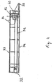
- Fig. 4 is a cross sectional view of the functional package according to the invention taken along line 4-4 in fig. 2b.
- Fig. 5 is a longitudinal sectional view of the functional package inside the recess of the cavity of the base machine.
- Telecommunication product suppliers will therefore have to market in large quantities, adapters designed to allow the I.S.D.N network connection for a large quantities of telecommunication Data Terminal Equipment (DTE) having different protocols and standarts, such as V24, V35 or X21 standards as defined by the CCITT.
- DTE Data Terminal Equipment
- Telecommunication product suppliers will therefore have to provide modular equipments, or functional packages, containing electronic components specific to particular protocols, and which when plugged into a base machine will allow the connection of a particular Data Terminal Equipment (for instance V35), to the I.S.D.N network.
- a machine in the illustrated instance a telecommunication adapter designed to be connected to a digital network, is illustrated therein.
- the machine or I.S.D.N. adapter 10 has its rear side, cavities or recesses in which functional package 12, 13 and 14 can be housed.
- each of functional packages 12 and 13 may contain electronic components mounted on a printed circuit board and allowing the connection of the machine 10 to a Data Terminal Equipment (DTE), not shown, by means of a cable 50, as illustrated in figure 5.
- DTE Data Terminal Equipment
- Functional package 14 contains electronic components allowing the connection of the machine to a digital network. Two perspective views of a typical functional package are shown in figures 2a and 2b.
- each of functional packages 12, 13 or 14 includes a printed circuit board 31 on which are mounted electronic components.
- a first connector 32 adapted to pluggably receive a male connector 54 (see fig. 5) secured to the base machine 10, is fixed to card 31, and allows the connection of the electronic components in the functional package to the components in machine 10.
- the printed circuit board 31 is protected by a housing comprising a top cover 33 and a bottom cover 34 which are fixed together as by a screw 37.
- the printed circuit board 31 further includes a second connector 35, designed to connect the functional package to an outside equipment by means of cable 50.
- a front plate 36 protects the rear side of the functional pack.
- each of the functional packages 12, 13 or 14 may be plugged into and removed from its associated cavity within machine 10 by means of a lever 38.
- lever 38 is structured so that the magnitude of the force to be exerted by an operator to insert or remove the functional package is a smal fraction of the magnitude of the force required to plug or unplug connectors 32 and 54. Without such an arrangement, the operator would have to exert a force of about 20 Newtons to connect or disconnect the package.
- Lever 38 comprises a handle 39 designed to be operator grippable and, as shown in figure 3, two upwardly extending side arms 40, each connected at first end thereof to handle 39.
- Each arm 40 carries a laterally extending pivot stud 41. and is provided at its second end with two upwardly projecting tooth elements 42, 43.
- Each pivot stud 41 is received in the cooperates with a pivot aperture formed in the longitudinaly extending side of the functional package housing.
- each pivot aperture is obtained by machining, within the top and bottom covers, two semi-circular notches which, upon assembling the top and bottom covers together, will form a single circular aperture for receiving pivot stud 41.
- Each tooth element 42, 43 is positioned with respect to its associated arm 40 and stud 41 so that, upon clockwise rotation (as shown in fig. 4) of lever 38 around studs 41, it will penetrate into an associated elongated aperture 45 formed within the top face of top cover 33, while during the same clockwise rotation, tooth element 42 will leave its associated aperture 44.
- the handle portion 39 of lever 38 is located with respect to connector 35 so that the presence of a connector plugged into connector 35 will prevent the lever 38 from being rotated counter clockwise as shown in figure 5. It should be noted that that counter clockwise rotation brings the handle of the lever 38 to its upper position.
- handle portion 39 it may be necessary to provide handle portion 39 with a supplementary upwardly extending protrusion part 59 which, by engaging the connector body, will prevent the rotation of handle portion 39, while not preventing plugging and unplugging of the connector 56 and its cable 50.
- Fig. 5 also shows that the cavity of machine 10 in which functional package 12, 13, 14 is received, is delimited by at least an upper wall 55 and a lower wall 60.
- package guiding means which can take the form of channel means in which package 12, 13 or 14 can be slidably inserted. It should be understood that such channel means must be sized with respect to the dimensions of package 12,13 or 14 so that they will permit only a longitudinal movement of the package within its cavity.
- Upper wall 55 is provided with a downward extending rail element 51. Rail element 51 extends transversely to the functional package guiding means. The height of rail 51 is such that its edges 52 and 53 interfere with tooth element 42, 43 of lever 38, unless the latter has been rotated to positions where the tooth elements 42, 43 will have cleared the edges of rail 51.
- a connector 56 When connector 54 is plugged into connector 32, a connector 56 may be plugged into connector 35 of functional package 14, assuring the connection of the machine to the digital network by means of a cable 50.
- a connector 56 since the insertion or extraction of this package in or out of the machine, when the cable 50 is plugged, may cause the occurence of voltage spikes due to excessive momentary loads. This may damage or destroy some internal components of the machine, or worst of all, injure badly the user.
- This problem is solved in the present invention by the presence of a protrusion 59, which prevents, as long as connector 56 remains plugged, the rotation of lever 38, and hence, the extraction of the functional package.
Landscapes
- Engineering & Computer Science (AREA)
- Microelectronics & Electronic Packaging (AREA)
- Computer Security & Cryptography (AREA)
- Details Of Connecting Devices For Male And Female Coupling (AREA)
- Mounting Of Printed Circuit Boards And The Like (AREA)
- Automatic Assembly (AREA)
Claims (6)
- Gerätesteckbarer elektronischer Einschub, der elektronische Bauelemente enthält und eine Verriegelung aufweist, wobei der Einschub (14) enthält: einen ersten Steckverbinder (32), der mit Steckverbindern, die an einem Gerät (10) befestigt sind, verbunden wird, wobei die Verbindung des Einschubs (14) mit dem Gerät (10) mittels schiebbarer Einführung des Einschubs (14) entlang von Führungsmitteln in das Gerät (10) durchgeführt wird und wobei der Einschub (14) umfaßt:- einen zweiten Steckverbinder (35), der mit Steckverbindern außerhalb des Geräts (10) und des Einschubs (14) verbunden wird,- einen Hebel (38), der drehbar an Drehmitteln (41) befestigt und am Einschub (14) abgesichert ist, wobei der Hebel (38) einen Handgriff (39) und zugehörige erste (43) und zweite (42) Verriegelungsmittel aufweist, wobei die ersten und zweiten Verriegelungsmittel (43, 42) vorgesehen sind, um selektiv mit dritten (52) und vierten (53) Verriegelungselementen in dem Gerät (10) zu kooperieren und- die Drehmittel (41), die so angeordnet sind, daß die ersten Verriegelungsmittel (43) kraftschlüssig in die dritten Verriegelungsmittel (52) nach einer Drehung des Hebels (38) in eine erste Richtung eingreifen und die so angeordnet sind, daß die zweiten Verriegelungsmittel (42) kraftschlüssig in die vierten Verriegelungsmittel (53) nach Drehung des Hebels (38) in eine zweite Richtung entgegengesetzt zu der ersten Richtung eingreifen, wobei die Drehung des Hebels (38) in die erste Richtung nach dem Einführen des Einschubs (14) entlang der Führungsmittel die ersten Steckverbinder (32) mit den Steckverbindern, die am Gerät (10) befestigt sind, koppelt und den Einschub (38) im Gerät verriegelt und wobei die Drehung des Hebels (38) in die zweite Richtung die ersten Steckverbinder (32) von den Steckverbindern, die am Gerät (109) befestigt sind, entkoppelt und den Einschub (14) von dem Gerät (10) entriegelt, wobei der Einschub dadurch gekennzeichnet ist, daß ein Handgriff (39) so positioniert ist, daß der Hebel (38) an der Drehung in die zweite Richtung gehindert wird, solange der äußere Steckverbinder mit dem zweiten Steckverbinder (35) verbunden ist.
- Gerätesteckbarer elektronischer Einschub gemäß Anspruch 1, dadurch gekennzeichnet, daß der Hebel (38) umfaßt:- zwei aufwärts sich erstreckende Seitenarme (40), wobei jeder der Arme (40) erste (43) und zweite (42) Verriegelungsmittel trägt,- jeder der Arme einen Drehbeschlag (41) umfaßt, der das Drehmittel bildet und entworfen ist, um mit einer Drehöffnung, die in der sich längserstreckenden Seite des funktionalen Einschubs eingeformt ist, zu kooperieren.
- Gerätesteckbarer elektronischer Einschub gemäß Anspruch 2, dadurch gekennzeichnet, daß der Einschub (14) eine Deckenabdeckung (33) und eine Bodenabdeckung (34), die zusammengehalten werden, einschließt, wobei jede der sich längserstreckenden Seiten der Abdeckungen zwei halbkreisförmige Aussparungen aufweisen, die nach dem Zusammenbau von Decken- (33) und Bodenabdeckung (34) eine einzige kreisförmige Öffnung zur Aufnahme von einem der Drehbeschläge (41) bilden.
- Gerätesteckbarer elektronischer Einschub gemäß Anspruch 3, dadurch gekennzeichnet, daß die ersten (43) und die zweiten (42) Verriegelungsmittel erste (43) und zweite (42) Zackenelemente sind, die auf jedem Arm (40) befestigt sind, wobei das erste Zackenelement (43) entsprechend zu seinem zugehörigen Arm (40) so positioniert wird, daß es nach einer Drehung des Hebels (38) im Uhrzeigersinn um den Drehbeschlag (41) herum in die erste zugehörige Öffnung (45) eindringt, die in der Oberseite der Deckenabdeckung (33) geformt ist und das zweite Zackenelement (42) die zweite zugehörige Öffnung verläßt (45).
- Gerätesteckbarer elektronischer Einschub gemäß Anspruch 4, dadurch gekennzeichnet, daß die Zackenelemente (42, 43) zum Eingreifen mit den Kantenabschnitten eines sich quererstreckenden Schienenelementes (51) angepaßt sind.
- Gerätesteckbarer elektronischer Einschub gemäß Anspruch 1 bis 5, dadurch gekennzeichnet, daß der Handgriff (39) mindestens einen Anbau enthält, dessen Größe von der Größe des äußeren Steckverbinders abhängt.
Priority Applications (6)
| Application Number | Priority Date | Filing Date | Title |
|---|---|---|---|
| EP88480009A EP0332793B1 (de) | 1988-03-15 | 1988-03-15 | Durch maschinelle Vorrichtung einsteckbarer elektronischer Einschub mit mechanischer Verriegelung |
| DE3886518T DE3886518T2 (de) | 1988-03-15 | 1988-03-15 | Durch maschinelle Vorrichtung einsteckbarer elektronischer Einschub mit mechanischer Verriegelung. |
| JP1010107A JP2553182B2 (ja) | 1988-03-15 | 1989-01-20 | マシンに挿入可能な電子パツケージ |
| CA000590145A CA1305780C (en) | 1988-03-14 | 1989-02-03 | Machine-pluggable electronic package having a mechanical interlock |
| AU29925/89A AU612234B2 (en) | 1988-03-15 | 1989-02-14 | Machine-pluggable electronic package having a mechanical interlock |
| US07/322,964 US4941835A (en) | 1988-03-15 | 1989-03-14 | Machine-pluggable electronic package having a mechanical interlock |
Applications Claiming Priority (1)
| Application Number | Priority Date | Filing Date | Title |
|---|---|---|---|
| EP88480009A EP0332793B1 (de) | 1988-03-15 | 1988-03-15 | Durch maschinelle Vorrichtung einsteckbarer elektronischer Einschub mit mechanischer Verriegelung |
Publications (2)
| Publication Number | Publication Date |
|---|---|
| EP0332793A1 EP0332793A1 (de) | 1989-09-20 |
| EP0332793B1 true EP0332793B1 (de) | 1993-12-22 |
Family
ID=8200491
Family Applications (1)
| Application Number | Title | Priority Date | Filing Date |
|---|---|---|---|
| EP88480009A Expired - Lifetime EP0332793B1 (de) | 1988-03-14 | 1988-03-15 | Durch maschinelle Vorrichtung einsteckbarer elektronischer Einschub mit mechanischer Verriegelung |
Country Status (6)
| Country | Link |
|---|---|
| US (1) | US4941835A (de) |
| EP (1) | EP0332793B1 (de) |
| JP (1) | JP2553182B2 (de) |
| AU (1) | AU612234B2 (de) |
| CA (1) | CA1305780C (de) |
| DE (1) | DE3886518T2 (de) |
Families Citing this family (24)
| Publication number | Priority date | Publication date | Assignee | Title |
|---|---|---|---|---|
| US5061845A (en) * | 1990-04-30 | 1991-10-29 | Texas Instruments Incorporated | Memory card |
| AU637532B2 (en) * | 1990-10-17 | 1993-05-27 | Fujitsu Limited | Test connector for electronic circuit units |
| US5224870A (en) * | 1991-01-11 | 1993-07-06 | Physio-Control Corporation | Battery pack |
| US5208732A (en) * | 1991-05-29 | 1993-05-04 | Texas Instruments, Incorporated | Memory card with flexible conductor between substrate and metal cover |
| EP0530829A2 (de) * | 1991-09-06 | 1993-03-10 | Kabushiki Kaisha Toshiba | Elektronikgerätesystem mit Elektronikgeräteinheit und Erweiterungseinheit zur Erweiterung der Funktion der Elektronikgeräteinheit |
| US5541448A (en) * | 1991-10-16 | 1996-07-30 | Texas Instruments Inc. | Electronic circuit card |
| JPH05238324A (ja) * | 1992-02-27 | 1993-09-17 | Sony Corp | 車載用機器の取付け装置 |
| US5381684A (en) * | 1992-02-27 | 1995-01-17 | Sony Corporation | Detachable apparatus for automotive audio equipment |
| US5485672A (en) * | 1993-06-21 | 1996-01-23 | Texas Instruments Incorporated | Method for encasing a printed wiring board |
| US5572141A (en) * | 1994-03-09 | 1996-11-05 | At&T Global Information Solutions Company | Memory metal hot plug connector and method |
| US5586003A (en) * | 1995-06-07 | 1996-12-17 | Dell Usa, L.P. | Computer device carrier door and bay filler panel combination including gear and guide pin |
| USD416885S (en) * | 1998-08-05 | 1999-11-23 | Honda Tsushin Kogyo Co., Ltd. | Lower metal cover for compact flash card |
| USD416884S (en) * | 1998-08-05 | 1999-11-23 | Honda Tsushin Kogyo Co., Ltd. | Upper metal cover for compact flash card |
| USD442964S1 (en) | 1999-10-05 | 2001-05-29 | Honda Tsushin Kogyo Co., Ltd. | Lower metal cover for compact flash card |
| USD434771S (en) * | 1999-10-05 | 2000-12-05 | Honda Tsushin Kogyo Co., Ltd. | Upper metal cover for compact flash card |
| TW492617U (en) * | 2000-11-10 | 2002-06-21 | Acard Technology Corp | Automatic disk rejecting device and disk array seat with automatic disk rejecting device |
| DE50306934D1 (de) | 2003-01-03 | 2007-05-10 | Rohde & Schwarz | Messgerätmodule und messgerät |
| DE10326388A1 (de) * | 2003-01-03 | 2004-07-15 | Rohde & Schwarz Gmbh & Co. Kg | Messgerätmodule und Messgerät |
| USD548739S1 (en) * | 2004-09-30 | 2007-08-14 | Japan Aviation Electronics Industry, Limited | Connector frame |
| DE102006013944B3 (de) * | 2006-03-27 | 2007-11-08 | Vector Informatik Gmbh | Ankopplungsvorrichtung mit steckbarem Modul zur Ankopplung eines Diagnosegeräts |
| EP2603067B1 (de) * | 2011-12-09 | 2015-09-23 | DET International Holding Limited | Verriegelungsvorrichtung |
| USD868787S1 (en) * | 2017-10-17 | 2019-12-03 | Intel Corporation | Peripheral component interconnect card with bracket |
| US11564306B2 (en) * | 2020-08-26 | 2023-01-24 | Jute Industrial Co., Ltd. | Vehicle lighting control circuit box |
| CN114952234B (zh) * | 2022-05-09 | 2023-10-10 | 世源科技(嘉兴)医疗电子有限公司 | 一种生产效率高的扎带组装设备 |
Citations (1)
| Publication number | Priority date | Publication date | Assignee | Title |
|---|---|---|---|---|
| DE3322856A1 (de) * | 1983-06-24 | 1985-01-03 | Siemens AG, 1000 Berlin und 8000 München | Frontsystem fuer in baugruppentraeger einschiebbare steckbaugruppen und rahmenartige baugruppentraeger zu deren aufnahme |
Family Cites Families (9)
| Publication number | Priority date | Publication date | Assignee | Title |
|---|---|---|---|---|
| US3271626A (en) * | 1964-12-31 | 1966-09-06 | Patrick P Howrilka | Printed circuit card rack |
| US3767974A (en) * | 1972-01-03 | 1973-10-23 | Cogar Corp | Insertion and extraction lever for printed circuit cards |
| US4301494A (en) * | 1979-09-28 | 1981-11-17 | Wescom, Inc. | Printed circuit board faceplate assembly |
| US4469388A (en) * | 1981-07-27 | 1984-09-04 | Thomas & Betts Corporation | Header for imposing frictional force on terminal posts |
| US4447101A (en) * | 1982-04-12 | 1984-05-08 | Litton Systems, Inc. | Connector with removable ejector latch |
| US4445740A (en) * | 1982-04-26 | 1984-05-01 | Rockwell International Corporation | Circuit board assembly |
| DE3465852D1 (en) * | 1984-06-07 | 1987-10-08 | Siemens Ag | Electrical enclosed functional unit |
| US4582381A (en) * | 1984-08-28 | 1986-04-15 | International Business Machines Corporation | Electrical interlock |
| DE8620241U1 (de) * | 1986-07-29 | 1986-10-23 | Eberle GmbH, 8500 Nürnberg | Vorrichtung zum Verriegeln und Ausrichten einer Frontplatte |
-
1988
- 1988-03-15 EP EP88480009A patent/EP0332793B1/de not_active Expired - Lifetime
- 1988-03-15 DE DE3886518T patent/DE3886518T2/de not_active Expired - Lifetime
-
1989
- 1989-01-20 JP JP1010107A patent/JP2553182B2/ja not_active Expired - Lifetime
- 1989-02-03 CA CA000590145A patent/CA1305780C/en not_active Expired
- 1989-02-14 AU AU29925/89A patent/AU612234B2/en not_active Ceased
- 1989-03-14 US US07/322,964 patent/US4941835A/en not_active Expired - Fee Related
Patent Citations (1)
| Publication number | Priority date | Publication date | Assignee | Title |
|---|---|---|---|---|
| DE3322856A1 (de) * | 1983-06-24 | 1985-01-03 | Siemens AG, 1000 Berlin und 8000 München | Frontsystem fuer in baugruppentraeger einschiebbare steckbaugruppen und rahmenartige baugruppentraeger zu deren aufnahme |
Non-Patent Citations (1)
| Title |
|---|
| IBM TECHNICAL DISCLOSURE BULLETIN, vol. 27, no. 6, November 1984, New York, US; pages 3536-3538, G.J.CLAIR: "Lever-secured pluggable circuit card enclosure" * |
Also Published As
| Publication number | Publication date |
|---|---|
| CA1305780C (en) | 1992-07-28 |
| AU2992589A (en) | 1989-09-21 |
| AU612234B2 (en) | 1991-07-04 |
| DE3886518D1 (de) | 1994-02-03 |
| DE3886518T2 (de) | 1994-06-30 |
| EP0332793A1 (de) | 1989-09-20 |
| US4941835A (en) | 1990-07-17 |
| JP2553182B2 (ja) | 1996-11-13 |
| JPH01241897A (ja) | 1989-09-26 |
Similar Documents
| Publication | Publication Date | Title |
|---|---|---|
| US4941835A (en) | Machine-pluggable electronic package having a mechanical interlock | |
| US3569914A (en) | Connector housing | |
| EP0600120B1 (de) | Elektrisches Steckverbindungssystem | |
| US4313150A (en) | Latching lever for printed circuit boards | |
| JP2514241B2 (ja) | 回路カ―ド収容装置 | |
| US6229709B1 (en) | Printed circuit board card guide | |
| US3971619A (en) | Safe electrical connector | |
| US4858309A (en) | Extraction tool | |
| US5477418A (en) | I/O connector for add in printed circuit cards for computer systems | |
| GB2328085A (en) | Holder for circuit card | |
| JPH07109948B2 (ja) | 回路カード収容装置 | |
| EP0630080A2 (de) | Leiterplatte mit darauf montierter modularen Telefonsteckerbuchse | |
| JP2559833Y2 (ja) | モジューラ電気コネクタ用ホルダ | |
| EP0461841A2 (de) | Abgeschirmter elektrischer Klinkenverbinder | |
| US5015201A (en) | Wiring device with improved push-wire termination release | |
| EP0622868A2 (de) | Anschlussdosen-Montagesatz für Datenübertragung | |
| JP2602471B2 (ja) | 電気コネクタ取付装置 | |
| EP0522798B1 (de) | Elektrischer Verbinder | |
| TW294849B (de) | ||
| US4886942A (en) | Strain relief structure for connecting flat flexible cable to a circuit board | |
| US5088932A (en) | Electrical connector | |
| US4702712A (en) | Keyed insulator apparatus | |
| EP0612124B1 (de) | Elektrischer Ein-Ausgangsverbinder | |
| CA1123503A (en) | Latching lever for printed circuit boards | |
| JP3266064B2 (ja) | 導通コネクタ |
Legal Events
| Date | Code | Title | Description |
|---|---|---|---|
| PUAI | Public reference made under article 153(3) epc to a published international application that has entered the european phase |
Free format text: ORIGINAL CODE: 0009012 |
|
| AK | Designated contracting states |
Kind code of ref document: A1 Designated state(s): BE CH DE ES FR GB IT LI NL SE |
|
| 17P | Request for examination filed |
Effective date: 19900120 |
|
| 17Q | First examination report despatched |
Effective date: 19920708 |
|
| GRAA | (expected) grant |
Free format text: ORIGINAL CODE: 0009210 |
|
| AK | Designated contracting states |
Kind code of ref document: B1 Designated state(s): BE CH DE ES FR GB IT LI NL SE |
|
| PG25 | Lapsed in a contracting state [announced via postgrant information from national office to epo] |
Ref country code: SE Effective date: 19931222 Ref country code: NL Effective date: 19931222 Ref country code: ES Free format text: THE PATENT HAS BEEN ANNULLED BY A DECISION OF A NATIONAL AUTHORITY Effective date: 19931222 Ref country code: BE Effective date: 19931222 |
|
| REF | Corresponds to: |
Ref document number: 3886518 Country of ref document: DE Date of ref document: 19940203 |
|
| ET | Fr: translation filed | ||
| ITF | It: translation for a ep patent filed | ||
| NLV1 | Nl: lapsed or annulled due to failure to fulfill the requirements of art. 29p and 29m of the patents act | ||
| PLBE | No opposition filed within time limit |
Free format text: ORIGINAL CODE: 0009261 |
|
| STAA | Information on the status of an ep patent application or granted ep patent |
Free format text: STATUS: NO OPPOSITION FILED WITHIN TIME LIMIT |
|
| 26N | No opposition filed | ||
| PGFP | Annual fee paid to national office [announced via postgrant information from national office to epo] |
Ref country code: CH Payment date: 19950622 Year of fee payment: 8 |
|
| PG25 | Lapsed in a contracting state [announced via postgrant information from national office to epo] |
Ref country code: LI Effective date: 19960331 Ref country code: CH Effective date: 19960331 |
|
| REG | Reference to a national code |
Ref country code: CH Ref legal event code: PL |
|
| PGFP | Annual fee paid to national office [announced via postgrant information from national office to epo] |
Ref country code: GB Payment date: 19970224 Year of fee payment: 10 |
|
| PGFP | Annual fee paid to national office [announced via postgrant information from national office to epo] |
Ref country code: FR Payment date: 19970304 Year of fee payment: 10 |
|
| PG25 | Lapsed in a contracting state [announced via postgrant information from national office to epo] |
Ref country code: GB Free format text: LAPSE BECAUSE OF NON-PAYMENT OF DUE FEES Effective date: 19980315 |
|
| PG25 | Lapsed in a contracting state [announced via postgrant information from national office to epo] |
Ref country code: FR Free format text: THE PATENT HAS BEEN ANNULLED BY A DECISION OF A NATIONAL AUTHORITY Effective date: 19980331 |
|
| GBPC | Gb: european patent ceased through non-payment of renewal fee |
Effective date: 19980315 |
|
| REG | Reference to a national code |
Ref country code: FR Ref legal event code: ST |
|
| PGFP | Annual fee paid to national office [announced via postgrant information from national office to epo] |
Ref country code: DE Payment date: 19990322 Year of fee payment: 12 |
|
| PG25 | Lapsed in a contracting state [announced via postgrant information from national office to epo] |
Ref country code: DE Free format text: LAPSE BECAUSE OF THE APPLICANT RENOUNCES Effective date: 20000226 |
|
| PG25 | Lapsed in a contracting state [announced via postgrant information from national office to epo] |
Ref country code: IT Free format text: LAPSE BECAUSE OF NON-PAYMENT OF DUE FEES Effective date: 20050315 |