EP0167823B1 - Kompensationssystem für einen Positionskodierer - Google Patents
Kompensationssystem für einen Positionskodierer Download PDFInfo
- Publication number
- EP0167823B1 EP0167823B1 EP85106920A EP85106920A EP0167823B1 EP 0167823 B1 EP0167823 B1 EP 0167823B1 EP 85106920 A EP85106920 A EP 85106920A EP 85106920 A EP85106920 A EP 85106920A EP 0167823 B1 EP0167823 B1 EP 0167823B1
- Authority
- EP
- European Patent Office
- Prior art keywords
- encoder
- signals
- phase
- providing
- scale
- Prior art date
- Legal status (The legal status is an assumption and is not a legal conclusion. Google has not performed a legal analysis and makes no representation as to the accuracy of the status listed.)
- Expired - Lifetime
Links
- 238000006073 displacement reaction Methods 0.000 claims description 13
- 230000000295 complement effect Effects 0.000 description 5
- 230000003287 optical effect Effects 0.000 description 5
- 230000010363 phase shift Effects 0.000 description 5
- 238000005259 measurement Methods 0.000 description 4
- 238000010586 diagram Methods 0.000 description 3
- 238000000034 method Methods 0.000 description 3
- 230000000737 periodic effect Effects 0.000 description 2
- 238000005452 bending Methods 0.000 description 1
- 230000008602 contraction Effects 0.000 description 1
- 230000001419 dependent effect Effects 0.000 description 1
- 238000009434 installation Methods 0.000 description 1
- 238000012886 linear function Methods 0.000 description 1
- 238000004519 manufacturing process Methods 0.000 description 1
Images


Classifications
-
- G—PHYSICS
- G01—MEASURING; TESTING
- G01D—MEASURING NOT SPECIALLY ADAPTED FOR A SPECIFIC VARIABLE; ARRANGEMENTS FOR MEASURING TWO OR MORE VARIABLES NOT COVERED IN A SINGLE OTHER SUBCLASS; TARIFF METERING APPARATUS; MEASURING OR TESTING NOT OTHERWISE PROVIDED FOR
- G01D5/00—Mechanical means for transferring the output of a sensing member; Means for converting the output of a sensing member to another variable where the form or nature of the sensing member does not constrain the means for converting; Transducers not specially adapted for a specific variable
- G01D5/12—Mechanical means for transferring the output of a sensing member; Means for converting the output of a sensing member to another variable where the form or nature of the sensing member does not constrain the means for converting; Transducers not specially adapted for a specific variable using electric or magnetic means
- G01D5/244—Mechanical means for transferring the output of a sensing member; Means for converting the output of a sensing member to another variable where the form or nature of the sensing member does not constrain the means for converting; Transducers not specially adapted for a specific variable using electric or magnetic means influencing characteristics of pulses or pulse trains; generating pulses or pulse trains
- G01D5/24471—Error correction
- G01D5/2448—Correction of gain, threshold, offset or phase control
-
- G—PHYSICS
- G01—MEASURING; TESTING
- G01D—MEASURING NOT SPECIALLY ADAPTED FOR A SPECIFIC VARIABLE; ARRANGEMENTS FOR MEASURING TWO OR MORE VARIABLES NOT COVERED IN A SINGLE OTHER SUBCLASS; TARIFF METERING APPARATUS; MEASURING OR TESTING NOT OTHERWISE PROVIDED FOR
- G01D18/00—Testing or calibrating apparatus or arrangements provided for in groups G01D1/00 - G01D15/00
- G01D18/001—Calibrating encoders
-
- G—PHYSICS
- G01—MEASURING; TESTING
- G01D—MEASURING NOT SPECIALLY ADAPTED FOR A SPECIFIC VARIABLE; ARRANGEMENTS FOR MEASURING TWO OR MORE VARIABLES NOT COVERED IN A SINGLE OTHER SUBCLASS; TARIFF METERING APPARATUS; MEASURING OR TESTING NOT OTHERWISE PROVIDED FOR
- G01D5/00—Mechanical means for transferring the output of a sensing member; Means for converting the output of a sensing member to another variable where the form or nature of the sensing member does not constrain the means for converting; Transducers not specially adapted for a specific variable
- G01D5/12—Mechanical means for transferring the output of a sensing member; Means for converting the output of a sensing member to another variable where the form or nature of the sensing member does not constrain the means for converting; Transducers not specially adapted for a specific variable using electric or magnetic means
- G01D5/244—Mechanical means for transferring the output of a sensing member; Means for converting the output of a sensing member to another variable where the form or nature of the sensing member does not constrain the means for converting; Transducers not specially adapted for a specific variable using electric or magnetic means influencing characteristics of pulses or pulse trains; generating pulses or pulse trains
- G01D5/24471—Error correction
- G01D5/2449—Error correction using hard-stored calibration data
Definitions
- the present invention relates to a system for compensating for scale error for use with a position encoder in accordance with the prior art portion of Claim 1.
- Electro-optical incremental encoders or transducers are known for measurement of linear or rotary motion or position.
- Such encoders include a scale of alternately light responsive and opaque segments which is cooperative with an optical head to provide an optical pattern representative of motion of the head relative to the scale. Electrical signals are derived from the optical pattern which represent the relative motion, and these signals are usually processed to produce a digital count indicative of distance travelled by the head relative to the scale.
- Scale errors such as variations in the width and spacing of the scale segments can cause errors in measurement of distance along the intended path. Such errors can become significant especially in high resolution encoders in which a high density optical pattern is provided on the encoder scale.
- Scale error has been treated heretofore by adjustment in the encoder electronics to add or subtract a single count at predetermined intervals of distance along the scale to alter proportionally the total count in order to minimize the error component.
- This type of compensation is not satisfactory in that the count correction is made in a single step at predetermined intervals of encoder travel, and the compensation is especially unsatisfactory if motion is being sensed in the vicinity of the scale at which the compensating count is provided. Similar errors can occur in position encoders or transducers of other than electro-optical type.
- a system for compensating for scale error of the above-mentioned type is known from EP-A-0 085 148.
- This prior art compensating system for use with a position encoder having a scale and a head movable relative to the scale and providing encoder signals representing the position of the head relative to the scale comprises means for providing a correction signal in the form of at least one correction track disposed parallel to the incremental divisions of the measuring scale.
- This prior art system requires that correction information be encoded on the at least one correction track. If further requires an additional sensor for scanning the correction track. Correction signals are only generated by this prior art system while the scanning sensor is scanning the at least one correction track.
- EP-A-0 042 917 discloses a method of interval interpolation, that is the subdivision of a signal period. In this method, correction values are automatically determined and stored in a computer. There is no specific disclosure in this reference as to the relationship between the signal period and the subdivision thereof. The position measuring system of this reference requires a plurality of detector elements to generate respective correction signals during relative movement between the scale and the scanning unit.
- This reference teaches only that the analog signals are input to amplifiers and therefrom to trigger circuits which convert the analog signals into squarewave signals.
- the squarewave signals are input to a direction discriminator which generates impulses and outputs these to an up/down counter.
- this reference teaches only a position measuring system wherein the periodic sinusoidal scanning motion is converted into a periodic squarewave waveform.
- FR-A-2 509 851 discloses a system for compensating for encoder scale error by using a memory for storing deviation values concerning the deviation of the encoder with regard to the linear function. These deviations are determined during a calibration step.
- GB-A-2 100 423 discloses an incremental optical encoder which does not generate or even use any type of correction signal to compensate for scale errors. Rather, phase shifting within the quadrant multiplier is used to electronically divide one code cycle into 32 or 64 segments, thereby providing a high resolution output signal. Further, as shown in the Table, the input resistors in each of the quadrant multipliers are dissimilar.
- the present invention is based on the object of providing a system for compensating for scale error of the above-mentioned kind which does not require a correction track.
- the system in accordance with the present invention neither requires any correction track nor is the generation of a correction signal dependent of scanning operation between the head and the scale. Rather, any error plot is developed for any particular encoder scale and from this error plot a "best straight line" is fitted to the measured points to provide a straight line error function.
- the invention is employed with a linear encoder which includes an elongated scale disposed along a path to be monitored, and an electro-optical head which is mounted for movement relative to the scale and which provides electrical signals representative of relative motion or position along the travel path.
- the head is fixed to a machine tool or other apparatus, while the scale is attached to a movable element for motion forward and backward along the length of the scale.
- the encoder output is usually a measure of the distance travelled by the scale along the head with respect to a reference position, and is often in the form of a numerical display indicative of distance.
- the encoder output signals can also be employed in a control system for automatic control of machine elements and the like.
- the linear encoder scale has errors which can result in corresponding errors in output measurement.
- the scale errors are caused by variations in the width and/or spacing of the light responsive segments, which variations are caused by errors or variations in the manufacture of the scale, thermal expansion and contraction of the scale during use or bending of the scale in an installed position.
- a typical error plot for a linear encoder scale is illustrated in Fig. 1.
- a succession of measurement points are plotted along a scale length L.
- a best straight line (BSL) is fitted to the measured points to provide a straight line error function having a slope E/L. This best straight line error function is a good approximation of the actual error and is advantageous in its simplicity of utilization in the novel compensation system of the present invention.
- the best straight line function can be represented by a number which is indicative of the slope of the error curve and a sign signal or bit which denotes the positive or negative senss of the slope.
- the slope of the BSL curve is independent of the line density or resolution of the encoder scale.
- the system embodying the invention is shown in block diagram form in Fig. 2.
- An encoder 10 provides an electrical output of four sine wave signals, +S, -S, +C and -C.
- the signals are composed of two complementary pairs of sine waves each phase displaced from the other by 90 degrees.
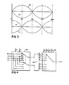
- four quadrature phased signals are provided, as illustrated in Fig. 3.
- These signals are applied to a displacement counter 12 which is operative to provide an output pulse for each predetermined movement of the encoder scale relative to the encoder head.
- the counter 12 provides an increment output pulse for relative motion of one direction and a decrement output pulse for relative motion of the opposite direction.
- a preset input to counter 12 is provided by control 14.
- the control 14 provides the displacement increment for which counter 12 will provide an output.
- the counter 12 provides an increment pulse or a decrement pulse, in accordance with the sense of motion.
- the output of counter 12 is applied via a reversing switch 16 to a phase control counter 18.
- the reversing switch is controlled by the sign bit from control 14.
- the sign of the error slope is determined when the error function is initially plotted.
- the sign bit input from control 14 to counter 12 is then set for that particular scale error. If a different scale is installed, an error plot for this new scale would be made, and the slope of the error curve determined.
- the sign bit from control 14 will be set to be positive or negative depending upon the slope of the error curve for the new scale.
- the BSL curve of Fig. 1 has a positive slope, and thus a positive sign bit is provided by control 14 to switch 16.
- the switch remains in the position shown for the particular error slope. If the error slope were negative, the switch position would be reversed.
- the preset value N applied by control 14 to counter 12 is determined by: where K is the portion of the line-space cycle of the encoder scale by which the phase is shifted; and E/L is the slope of the best straight line error function.
- K is 1/64 and therefore a phase correction is made for each 1/64th of a scale cycle or 5.625 degrees, which corresponds to 0,794 mm.
- the line-space cycle ACy is 50,8 pm and a best straight line error slope (E/L) of 25x 10- 6 (25 ppm)
- the value N is 625.
- the counter 18 provides a multiple bit digital signal representative of the number of displacement increments traversed by the encoder scale relative to the head. This counter output signifies the total phase compensation which is to be made.
- the output signal or code from counter 18 is employed to control the operation of the quadrant switches 20 and 22 and the multiplex switches 28 and 30 to accomplish the desired phase correction.
- the bits X 4 and X s specify the quadrant of the accumulated phase compensation.
- the bits X o -X 3 specify the phase of the selected quadrant to be added to the encoder signal phase for purposes of correction.
- the quadrant switches 20 and 22 are controlled by the two most significant bits (X 4 , X S ) of the output signal from counter 18.
- the output of each quadrant switch is applied to respective resistor networks 24 and 26, the outputs of which are applied to respective multiplex switches 28 and 30.
- the four least significant bits (X O- X 3 ) of the output signal from counter 18 are employed to control the operation of the multiplex switches 28 and 30.
- the output of switch 28 provides the compensated encoder signal +S', and after inversion by the inverter 32 provides the complementary encoder signal -S'.
- the switch 30 provides the compensated encoder signal -C', and after inversion by inverter 34 provides the complementary encoder signal +C'.
- the quadrant switch 20 is illustrated schematically in Fig. 4 together with the associated resistor network 24 and multiplex switch 28.
- the quadrant-switch 22 is similarly implemented.
- the quadrant switch 20, resistor network 24 and multiplex switch 28 comprise a sine channel, while a cosine channel is provided by quadrant switch 22, resistor network 26 and multiplex switch 30.
- the quadrant switches 20 and 22 provide quadrature phased signals to the respective resistor networks for each phase quadrant of the accumulated phase applied encoder signals.
- the quadrature information is provided by the encoder signals +S and -C. As shown in Fig.
- the quadrant switch 20 couples the signals +S and -C to the resistor network 24.
- the switch 20 will be connected to the switch taps to couple the signals -S and -C to the resistor network 24.
- the switch 20 couples the signals -S and +C to the resistor network.
- the switch 20 couples the signals +C and +S to the resistor network.
- Each tap of the resistor networks 24 and 26 provides a weighted sum of the applied signals to produce the desired phase shift for phase compensation.
- the multiplex switches 28 and 30 are operative to select sequentially each of the taps of the corresponding resistor networks 24 and 26.
- the number of resistors and resistor taps is provided in accordance with the intended phase compensation factor which is to be added (or subtracted) to the encoder signal to provide compensation.
- sixteen resistors are provided to provide a compensation factor of 5.625 degrees (90°/16).
- the switches 28 and 30 are each operative to switch to a succeeding tap of respective resistor networks 24 and 26 for each preselected incremental movement of the encoder.
- the switches 28 and 30 each select the next tap of the respective networks 24 and 26, as governed by the digital code from counter 18.
- Phase compensation in increments of 5.625 degrees is provided by the networks 28 and 30.
- tap 1 of network 24 provides 5.625 degrees of phase shift
- tap 2 provides twice this phase shift
- tap 3 provides three times the 5.625 degree amount etc.
- Network 26 is operative in the same manner.
- the networks 24 and 26 can be considered as two legs of a resistor bridge.
- the network 24 provides first quadrant correction.
- the network 26 provides second quadrant correction. Since third quadrant signals are complementary to those of the first quadrant, the compensation signals for the third quadrant are easily derived by inverting the signals provided by network 24.
- the compensation signals for the fourth quadrant are complementary to those of the second quadrant and are derived by inverted versions of the signals from network 26. This is as illustrated in Fig. 2 where the compensated signals +S' and -C' are provided by the respective networks 24 and 26, and the compensated signals -S' and +C' are derived by inversion of the respective signals +S' and -C'.
- the compensated signals are applied to cycle interpolation logic (Fig. 5) the outputs of which are applied to an output counter 38 which provides an output indication of encoder travel along the defined path.
- the cycle interpolation logic 36 is operative to increase the resolution of the encoder output signals and provides the enhanced resolution that would be provided by an encoder scale of greater line density, but without the necessity for such a finer resolution scale.
- the cycle interpolation technique is itself known in the art and is the subject of prior patents of the same inventor as herein; US-patents 3,265,902, 3,310,798 and 3,312,828.
Landscapes
- Physics & Mathematics (AREA)
- General Physics & Mathematics (AREA)
- Transmission And Conversion Of Sensor Element Output (AREA)
- Optical Transform (AREA)
- Measurement Of Length, Angles, Or The Like Using Electric Or Magnetic Means (AREA)
- Length Measuring Devices With Unspecified Measuring Means (AREA)
Claims (8)
daß die ersten und zweiten Einrichtungen (20, 24, 28, 32; 22, 26, 30, 34) zum Empfang der codierten Signale derart auf das Phasenkorrektursignal reagieren, daß sie die codierten Signale durch die gesamte Phasenkompensation ändern und so die phasenkompensierten codierten Signale liefern, die aufgrund des Codierskalenfehlers kompensiert wurden.
Applications Claiming Priority (2)
| Application Number | Priority Date | Filing Date | Title |
|---|---|---|---|
| US618509 | 1984-06-08 | ||
| US06/618,509 US4631520A (en) | 1984-06-08 | 1984-06-08 | Position encoder compensation system |
Publications (2)
| Publication Number | Publication Date |
|---|---|
| EP0167823A1 EP0167823A1 (de) | 1986-01-15 |
| EP0167823B1 true EP0167823B1 (de) | 1990-09-12 |
Family
ID=24478015
Family Applications (1)
| Application Number | Title | Priority Date | Filing Date |
|---|---|---|---|
| EP85106920A Expired - Lifetime EP0167823B1 (de) | 1984-06-08 | 1985-06-04 | Kompensationssystem für einen Positionskodierer |
Country Status (4)
| Country | Link |
|---|---|
| US (1) | US4631520A (de) |
| EP (1) | EP0167823B1 (de) |
| JP (1) | JPS614919A (de) |
| DE (1) | DE3579639D1 (de) |
Families Citing this family (15)
| Publication number | Priority date | Publication date | Assignee | Title |
|---|---|---|---|---|
| US4912468A (en) * | 1985-12-04 | 1990-03-27 | Dynamics Research Corporation | Non-linear error correction system |
| JPH061203B2 (ja) * | 1986-09-10 | 1994-01-05 | フアナツク株式会社 | デイジタルパルスのパルス幅確保およびノイズ抑制のための回路 |
| AT393030B (de) * | 1989-05-23 | 1991-07-25 | Rsf Elektronik Gmbh | Inkrementales messsystem |
| US5050135A (en) * | 1989-12-20 | 1991-09-17 | Unico, Inc. | Magnetostrictive multiple position sensing device |
| GB2281624A (en) * | 1993-07-30 | 1995-03-08 | Rover Group | Engine crankshaft position determination |
| US5640007A (en) * | 1995-06-21 | 1997-06-17 | Limitorque Corporation | Optical encoder comprising a plurality of encoder wheels |
| DE19945179C2 (de) * | 1999-09-21 | 2001-11-15 | Siemens Ag | Verfahren zur Vorgabe einer Rampe durch eine getaktete Größe |
| US6686585B2 (en) * | 2001-09-19 | 2004-02-03 | Microe Systems Corporation | Position encoder with scale calibration |
| JP2003121135A (ja) * | 2001-10-10 | 2003-04-23 | Futaba Corp | リニヤスケールの読出装置 |
| DE10160835B4 (de) * | 2001-12-06 | 2011-02-17 | Anton Rodi | Anordnung zur Interpolation eines Messsignals |
| US8882657B2 (en) * | 2003-03-07 | 2014-11-11 | Intuitive Surgical Operations, Inc. | Instrument having radio frequency identification systems and methods for use |
| US7126109B2 (en) * | 2004-06-14 | 2006-10-24 | Gsi Group Corporation | Encoder scale error compensation employing comparison among multiple detectors |
| EP2059770A4 (de) * | 2006-08-21 | 2012-07-18 | Gsi Group Corp | Optischer drehcodierer mit mehreren subcodierern mit einem gemeinsamen retikelsubstrat |
| JP4468981B2 (ja) * | 2007-10-12 | 2010-05-26 | オリンパス株式会社 | エンコーダ |
| CN115855128B (zh) * | 2022-11-11 | 2025-07-11 | 上海交通大学 | 基于组合式码道涡流栅位移传感器的位移检测方法 |
Citations (1)
| Publication number | Priority date | Publication date | Assignee | Title |
|---|---|---|---|---|
| EP0085148A2 (de) * | 1982-01-15 | 1983-08-10 | Dr. Johannes Heidenhain GmbH | Einrichtung zur Fehlerkorrektur bei Positionsmesssystemen |
Family Cites Families (10)
| Publication number | Priority date | Publication date | Assignee | Title |
|---|---|---|---|---|
| DE1552273B2 (de) * | 1965-01-28 | 1973-02-15 | Fujitsu Ltd, Kawasaki, Kanagawa (Japan) | Vorrichtung zum ausgleich der steigungsfehler einer vorschubspindel |
| DE2547885C3 (de) * | 1975-10-25 | 1980-05-08 | Dr. Johannes Heidenhain Gmbh, 8225 Traunreut | Elektronischer Zähler |
| JPS56153212A (en) * | 1980-04-30 | 1981-11-27 | Toshiba Corp | Encoder |
| JPS56159794A (en) * | 1980-05-12 | 1981-12-09 | Tokyo Optical | Length or angle measuring device |
| DE3024716C2 (de) * | 1980-06-30 | 1986-10-23 | Dr. Johannes Heidenhain Gmbh, 8225 Traunreut | Digitales Längen- oder Winkelmeßsystem |
| US4410798A (en) * | 1981-06-10 | 1983-10-18 | Itek Corporation | Incremental optical encoder system with addressable index |
| DE3128095A1 (de) * | 1981-07-16 | 1983-02-03 | Hartmann & Braun Ag, 6000 Frankfurt | "verfahren zur digitalen korrektur des zusammenhanges zwischen einem digitalen eingangssignal und einem digitalen ausgangssignal sowie schaltungsanordnung zur durchfuehrung dieses verfahrens" |
| FR2509851A1 (fr) * | 1981-07-17 | 1983-01-21 | Tesa Sa | Capteur electronique de mesure |
| DE3208591C2 (de) * | 1982-03-10 | 1986-06-05 | Dr. Johannes Heidenhain Gmbh, 8225 Traunreut | Digitales elektrisches Längen- oder Winkelmeßsystem |
| US4491826A (en) * | 1983-05-16 | 1985-01-01 | Danfoss A/S | Incremental digital converter |
-
1984
- 1984-06-08 US US06/618,509 patent/US4631520A/en not_active Expired - Lifetime
-
1985
- 1985-06-04 DE DE8585106920T patent/DE3579639D1/de not_active Expired - Lifetime
- 1985-06-04 EP EP85106920A patent/EP0167823B1/de not_active Expired - Lifetime
- 1985-06-08 JP JP60124996A patent/JPS614919A/ja active Pending
Patent Citations (1)
| Publication number | Priority date | Publication date | Assignee | Title |
|---|---|---|---|---|
| EP0085148A2 (de) * | 1982-01-15 | 1983-08-10 | Dr. Johannes Heidenhain GmbH | Einrichtung zur Fehlerkorrektur bei Positionsmesssystemen |
Also Published As
| Publication number | Publication date |
|---|---|
| JPS614919A (ja) | 1986-01-10 |
| US4631520A (en) | 1986-12-23 |
| DE3579639D1 (de) | 1990-10-18 |
| EP0167823A1 (de) | 1986-01-15 |
Similar Documents
| Publication | Publication Date | Title |
|---|---|---|
| EP0167823B1 (de) | Kompensationssystem für einen Positionskodierer | |
| US4912468A (en) | Non-linear error correction system | |
| EP0501453B1 (de) | Kombinierter optischer und kapazitiver Apparat zur Messung der absoluten Position | |
| US5010655A (en) | Incremental measuring system | |
| US4225931A (en) | Interpolation apparatus for digital electronic position measuring instrument | |
| US4318617A (en) | DC Shift error correction for electro-optical measuring system | |
| US5563408A (en) | Absolute encoder having absolute pattern graduations and incremental pattern graduations with phase control | |
| EP0039082B1 (de) | Verfahren und Einrichtung zum Messen der Verschiebung zwischen einer Kodierplatte und einer Sensoranordnung | |
| US4458322A (en) | Control of page storage among three media using a single channel processor program and a page transfer bus | |
| EP0042179A2 (de) | Codierer | |
| JPH0135286B2 (de) | ||
| GB2230666A (en) | Displacement detector | |
| US5021650A (en) | Method of electronically correcting position errors in an incremental measuring system and measuring system for carrying out the method | |
| EP1236973B1 (de) | Verfahren zur Veränderung von Interpolationsfaktoren | |
| JPH0410976B2 (de) | ||
| GB2156977A (en) | Length measuring device | |
| US4884226A (en) | Method for detecting position | |
| US3451054A (en) | Light optic digital transducer using displaced ronchi rulings | |
| EP0455984A1 (de) | Koordinatenmessmaschine mit verbesserter Interpolationsschaltung | |
| GB2156989A (en) | Device and method for measuring and adjusting lengths | |
| JPH05196451A (ja) | 測長または測角装置 | |
| EP0200791A1 (de) | Verfahren und vorrichtung zur bestimmung der ortung | |
| JP2754635B2 (ja) | アブソリュートエンコーダ | |
| EP1342993A2 (de) | Positionsgeber | |
| RU1779921C (ru) | Измерительный преобразователь перемещений |
Legal Events
| Date | Code | Title | Description |
|---|---|---|---|
| PUAI | Public reference made under article 153(3) epc to a published international application that has entered the european phase |
Free format text: ORIGINAL CODE: 0009012 |
|
| AK | Designated contracting states |
Designated state(s): CH DE FR GB IT LI NL |
|
| 17P | Request for examination filed |
Effective date: 19860224 |
|
| 17Q | First examination report despatched |
Effective date: 19870831 |
|
| GRAA | (expected) grant |
Free format text: ORIGINAL CODE: 0009210 |
|
| ITF | It: translation for a ep patent filed | ||
| AK | Designated contracting states |
Kind code of ref document: B1 Designated state(s): CH DE FR GB IT LI NL |
|
| ET | Fr: translation filed | ||
| REF | Corresponds to: |
Ref document number: 3579639 Country of ref document: DE Date of ref document: 19901018 |
|
| ITTA | It: last paid annual fee | ||
| PLBE | No opposition filed within time limit |
Free format text: ORIGINAL CODE: 0009261 |
|
| STAA | Information on the status of an ep patent application or granted ep patent |
Free format text: STATUS: NO OPPOSITION FILED WITHIN TIME LIMIT |
|
| 26N | No opposition filed | ||
| PGFP | Annual fee paid to national office [announced via postgrant information from national office to epo] |
Ref country code: GB Payment date: 19920602 Year of fee payment: 8 |
|
| PGFP | Annual fee paid to national office [announced via postgrant information from national office to epo] |
Ref country code: FR Payment date: 19920609 Year of fee payment: 8 |
|
| PGFP | Annual fee paid to national office [announced via postgrant information from national office to epo] |
Ref country code: NL Payment date: 19920630 Year of fee payment: 8 |
|
| PGFP | Annual fee paid to national office [announced via postgrant information from national office to epo] |
Ref country code: DE Payment date: 19920702 Year of fee payment: 8 |
|
| PGFP | Annual fee paid to national office [announced via postgrant information from national office to epo] |
Ref country code: CH Payment date: 19920928 Year of fee payment: 8 |
|
| PG25 | Lapsed in a contracting state [announced via postgrant information from national office to epo] |
Ref country code: GB Effective date: 19930604 |
|
| PG25 | Lapsed in a contracting state [announced via postgrant information from national office to epo] |
Ref country code: LI Effective date: 19930630 Ref country code: CH Effective date: 19930630 |
|
| PG25 | Lapsed in a contracting state [announced via postgrant information from national office to epo] |
Ref country code: NL Effective date: 19940101 |
|
| GBPC | Gb: european patent ceased through non-payment of renewal fee |
Effective date: 19930604 |
|
| NLV4 | Nl: lapsed or anulled due to non-payment of the annual fee | ||
| PG25 | Lapsed in a contracting state [announced via postgrant information from national office to epo] |
Ref country code: FR Effective date: 19940228 |
|
| REG | Reference to a national code |
Ref country code: CH Ref legal event code: PL |
|
| PG25 | Lapsed in a contracting state [announced via postgrant information from national office to epo] |
Ref country code: DE Effective date: 19940301 |
|
| REG | Reference to a national code |
Ref country code: FR Ref legal event code: ST |