EP0167978A2 - Saugrohrwärmetauscher und Verfahren zur Herstellung - Google Patents
Saugrohrwärmetauscher und Verfahren zur Herstellung Download PDFInfo
- Publication number
- EP0167978A2 EP0167978A2 EP85108234A EP85108234A EP0167978A2 EP 0167978 A2 EP0167978 A2 EP 0167978A2 EP 85108234 A EP85108234 A EP 85108234A EP 85108234 A EP85108234 A EP 85108234A EP 0167978 A2 EP0167978 A2 EP 0167978A2
- Authority
- EP
- European Patent Office
- Prior art keywords
- tube
- suction
- heat exchanger
- suction tube
- capillary tube
- Prior art date
- Legal status (The legal status is an assumption and is not a legal conclusion. Google has not performed a legal analysis and makes no representation as to the accuracy of the status listed.)
- Withdrawn
Links
Images

Classifications
-
- B—PERFORMING OPERATIONS; TRANSPORTING
- B21—MECHANICAL METAL-WORKING WITHOUT ESSENTIALLY REMOVING MATERIAL; PUNCHING METAL
- B21D—WORKING OR PROCESSING OF SHEET METAL OR METAL TUBES, RODS OR PROFILES WITHOUT ESSENTIALLY REMOVING MATERIAL; PUNCHING METAL
- B21D39/00—Application of procedures in order to connect objects or parts, e.g. coating with sheet metal otherwise than by plating; Tube expanders
- B21D39/04—Application of procedures in order to connect objects or parts, e.g. coating with sheet metal otherwise than by plating; Tube expanders of tubes with tubes; of tubes with rods
-
- F—MECHANICAL ENGINEERING; LIGHTING; HEATING; WEAPONS; BLASTING
- F25—REFRIGERATION OR COOLING; COMBINED HEATING AND REFRIGERATION SYSTEMS; HEAT PUMP SYSTEMS; MANUFACTURE OR STORAGE OF ICE; LIQUEFACTION SOLIDIFICATION OF GASES
- F25B—REFRIGERATION MACHINES, PLANTS OR SYSTEMS; COMBINED HEATING AND REFRIGERATION SYSTEMS; HEAT PUMP SYSTEMS
- F25B41/00—Fluid-circulation arrangements
- F25B41/30—Expansion means; Dispositions thereof
- F25B41/37—Capillary tubes
-
- F—MECHANICAL ENGINEERING; LIGHTING; HEATING; WEAPONS; BLASTING
- F25—REFRIGERATION OR COOLING; COMBINED HEATING AND REFRIGERATION SYSTEMS; HEAT PUMP SYSTEMS; MANUFACTURE OR STORAGE OF ICE; LIQUEFACTION SOLIDIFICATION OF GASES
- F25B—REFRIGERATION MACHINES, PLANTS OR SYSTEMS; COMBINED HEATING AND REFRIGERATION SYSTEMS; HEAT PUMP SYSTEMS
- F25B2400/00—Component parts or details not otherwise provided for in this subclass
- F25B2400/05—Compression system with heat exchange between particular parts of the system
- F25B2400/052—Compression system with heat exchange between particular parts of the system between the capillary tube and another part of the refrigeration cycle
-
- F—MECHANICAL ENGINEERING; LIGHTING; HEATING; WEAPONS; BLASTING
- F25—REFRIGERATION OR COOLING; COMBINED HEATING AND REFRIGERATION SYSTEMS; HEAT PUMP SYSTEMS; MANUFACTURE OR STORAGE OF ICE; LIQUEFACTION SOLIDIFICATION OF GASES
- F25B—REFRIGERATION MACHINES, PLANTS OR SYSTEMS; COMBINED HEATING AND REFRIGERATION SYSTEMS; HEAT PUMP SYSTEMS
- F25B2400/00—Component parts or details not otherwise provided for in this subclass
- F25B2400/05—Compression system with heat exchange between particular parts of the system
- F25B2400/054—Compression system with heat exchange between particular parts of the system between the suction tube of the compressor and another part of the cycle
-
- F—MECHANICAL ENGINEERING; LIGHTING; HEATING; WEAPONS; BLASTING
- F25—REFRIGERATION OR COOLING; COMBINED HEATING AND REFRIGERATION SYSTEMS; HEAT PUMP SYSTEMS; MANUFACTURE OR STORAGE OF ICE; LIQUEFACTION SOLIDIFICATION OF GASES
- F25B—REFRIGERATION MACHINES, PLANTS OR SYSTEMS; COMBINED HEATING AND REFRIGERATION SYSTEMS; HEAT PUMP SYSTEMS
- F25B40/00—Subcoolers, desuperheaters or superheaters
Definitions
- the present ivention concerns a heat exchanger of the so-called suction tube type for locating in the cooling circuit of a refrigerator/freezer in the compressor's suction line, and furthermore a method for manufacturing such heat exchangers.
- Heat exchangers of this type incorporated into cooling systems in conjunction with a compressor, comprise a capillary tube connected to the system's suction line.
- the purpose of this arrangement is that heat from the condensing fluid in the capillary tube is transferred to vapor drawn into the compressor through the suction tube. In this way, the efficiency of the cooling system is increased while simultaneously preventing the intake of unevaporated fluid into the compressor.
- the object of the present invention is therefore to provide a heat exchanger that is cheaper to manufacture, yet qualitatively on a par with the heat exchangers of this type hitherto known and used.
- Another object of the present invention is to provide a method for the fabrication of heat exchangers which provides a simple, effective, and mechanically/thermally reliable joint between the tubes in the heat exchanger. This is achieved by the heat exchanger and the fabrication method as stated in the characterizing parts of the patent claims 1 and 4 of the present application.
- the suction line is given an oval cross-section, which is transformed to an essentially circular cross-section in the joining process of plastic deformation.
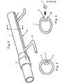
- a heat exchanger (8) is shown in more details, comprising a suction line (1) and a capillary tube (2) inserted and fastened in the groove (3) in the suction tube.
- Two standard tube fittings (9) connect the ends of the suction tube to the cooling circuit. (Only one of the fittings is shown in the figure.)
- Fig, 3 which shows a vertical cross-section of the heat exchanger at line A-A on Fig. 2, illustrates the superior joint between the suction tube (1) and the capillary tube (2), where up to 80% of the surface of the capillary tube is engaged, and thereby in heat-transferring contact with the walls of the suction line through the inwardly protruding groove (3).
- Fig. 4 shows both tubes in a vertical cross-section prior to the joining operation.
- the suction line (1) is illustrated in the preferred embodiment with an oval (elliptical) cross-section and an inwardly projecting groove (3) forming a recess in the tube's circumference.
- the cross-section of the groove and the diameter of the capillary tube are dimensioned to facilitate insertion of the tube into the groove.
- the subsequent plastic deformation of the suction line which is transformed to an essentially circular cross-section, results in the walls (32) of the groove being elongated around the perimeter of the tube, partly enclosing the capillary tube.
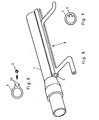
- FIG. 5 Another advantageous heat exchanger embodiment (8) according to the present invention is shown in Fig. 5.
- the integrated groove (3) in the suction line (1) is formed as a projection protruding out from the surface of the tube.
- the suction tube has an essentially circular cross-section.
- the plastic deformation occuring in the process of joining the tubes is limited in this case to the deformation of the walls of the groove (32), which encompass the capillary tube after joining, resulting in a solid, reliable mechanical and heat exchanging contact between the tubes.
- Fig. 7 shows still another embodiment of the suction tube ( 1 ) having an essentially circular cross-section with an inwardly protruding groove (3). Free surface of the capillary tube inserted and fastened in such a groove will achieve a direct contact with the circulating fluidum in the suction tube and result in further improvement of the heat transfer characteristic.
- the heat exchanger according to the invention is not limited to the preferred embodiments discussed above and illustrated in the figures. Different requirements as to heat exchanging capacity, compact design of the cooling system, etc., may call for the incorporation of more than one capillary tube per suction line, for instance without excluding this variant from the scope of the present invention.
- both the suction line and the capillary tube may be fabricated of aluminium, since neither the design nor the fabrication of heat exchangers according to the invention raise any limits on the choice of materials.
- aluminium applied as construction material provides obvious advantages in the form of weight reduction and less problems associated with connections and corrosion in the cooling circuit.
Landscapes
- Engineering & Computer Science (AREA)
- Mechanical Engineering (AREA)
- Physics & Mathematics (AREA)
- Thermal Sciences (AREA)
- General Engineering & Computer Science (AREA)
- Heat-Exchange Devices With Radiators And Conduit Assemblies (AREA)
- Saccharide Compounds (AREA)
- Seasonings (AREA)
Applications Claiming Priority (2)
| Application Number | Priority Date | Filing Date | Title |
|---|---|---|---|
| NO842755A NO155067C (no) | 1984-07-06 | 1984-07-06 | Sugeroersvarmeveksler og fremgangsmaate til fremstilling av samme. |
| NO842755 | 1984-07-06 |
Publications (2)
| Publication Number | Publication Date |
|---|---|
| EP0167978A2 true EP0167978A2 (de) | 1986-01-15 |
| EP0167978A3 EP0167978A3 (de) | 1986-06-11 |
Family
ID=19887755
Family Applications (1)
| Application Number | Title | Priority Date | Filing Date |
|---|---|---|---|
| EP85108234A Withdrawn EP0167978A3 (de) | 1984-07-06 | 1985-07-03 | Saugrohrwärmetauscher und Verfahren zur Herstellung |
Country Status (3)
| Country | Link |
|---|---|
| EP (1) | EP0167978A3 (de) |
| DK (1) | DK308485A (de) |
| NO (1) | NO155067C (de) |
Cited By (10)
| Publication number | Priority date | Publication date | Assignee | Title |
|---|---|---|---|---|
| EP0258040A1 (de) * | 1986-08-28 | 1988-03-02 | Sumitomo Chemical Company, Limited | Polyamid enthaltende thermoplastische Harzzusammensetzung |
| EP0749892A1 (de) * | 1995-05-26 | 1996-12-27 | Dr.Ing.h.c. F. Porsche Aktiengesellschaft | Träger einer Aufbaustruktur eines Fahrzeuges und Verfahren zu dessen Herstellung |
| US7243499B2 (en) * | 2004-08-16 | 2007-07-17 | Parker Hannifin Corporation | Refrigeration capillary tube inside suction line assembly |
| CN102313403A (zh) * | 2011-09-13 | 2012-01-11 | 海尔集团公司 | 蒸发器总成、制冷回路系统及制冷设备 |
| CN103673422A (zh) * | 2013-12-14 | 2014-03-26 | 广东奥马电器股份有限公司 | 一种节能回气管组件、加工方法及模具 |
| CN107178935A (zh) * | 2016-03-11 | 2017-09-19 | 福特全球技术公司 | 嵌套式暖通空调管线 |
| US9821420B2 (en) | 2014-01-16 | 2017-11-21 | Whirlpool Corporation | Method of forming a refrigeration heat exchanger |
| CN107806726A (zh) * | 2017-10-19 | 2018-03-16 | 合肥华凌股份有限公司 | 干燥过滤器、回气管组件及制冷设备 |
| DE102017110706A1 (de) * | 2017-05-17 | 2018-11-22 | Miele & Cie. Kg | Drosselvorrichtung für eine Wärmepumpe und Wärmepumpe mit einer Drosselvorrichtung |
| JP2020186887A (ja) * | 2019-05-17 | 2020-11-19 | アクア株式会社 | 冷蔵庫 |
Families Citing this family (1)
| Publication number | Priority date | Publication date | Assignee | Title |
|---|---|---|---|---|
| CN112696857A (zh) * | 2020-12-28 | 2021-04-23 | 南京祥斯知商贸有限公司 | 一种节能冰箱 |
Family Cites Families (5)
| Publication number | Priority date | Publication date | Assignee | Title |
|---|---|---|---|---|
| US2415243A (en) * | 1943-10-20 | 1947-02-04 | Bohn Aluminium & Brass Corp | Refrigeration apparatus and method of making same |
| US2687626A (en) * | 1952-02-16 | 1954-08-31 | Bohn Aluminium & Brass Corp | Heat exchanger having open-sided bore superimposed on closed bore |
| US3448798A (en) * | 1967-01-26 | 1969-06-10 | Wakefield Eng Inc | Heat transfer apparatus |
| CA1106628A (en) * | 1976-10-27 | 1981-08-11 | Robert B. Gelbard | High efficiency heat exchanger for refrigeration suction line/capillary tube assembly |
| IT8253373V0 (it) * | 1982-06-02 | 1982-06-02 | Indesit | Circuito frigorifero del tipo con capillare di espansione e ciclo a recupero termico |
-
1984
- 1984-07-06 NO NO842755A patent/NO155067C/no unknown
-
1985
- 1985-07-03 EP EP85108234A patent/EP0167978A3/de not_active Withdrawn
- 1985-07-05 DK DK308485A patent/DK308485A/da not_active Application Discontinuation
Cited By (11)
| Publication number | Priority date | Publication date | Assignee | Title |
|---|---|---|---|---|
| EP0258040A1 (de) * | 1986-08-28 | 1988-03-02 | Sumitomo Chemical Company, Limited | Polyamid enthaltende thermoplastische Harzzusammensetzung |
| EP0749892A1 (de) * | 1995-05-26 | 1996-12-27 | Dr.Ing.h.c. F. Porsche Aktiengesellschaft | Träger einer Aufbaustruktur eines Fahrzeuges und Verfahren zu dessen Herstellung |
| US5839777A (en) * | 1995-05-26 | 1998-11-24 | Dr. Ing. H.C.F. Porsche Ag | Support of a body structure of a vehicle and process for manufacturing same |
| US7243499B2 (en) * | 2004-08-16 | 2007-07-17 | Parker Hannifin Corporation | Refrigeration capillary tube inside suction line assembly |
| CN102313403A (zh) * | 2011-09-13 | 2012-01-11 | 海尔集团公司 | 蒸发器总成、制冷回路系统及制冷设备 |
| CN103673422A (zh) * | 2013-12-14 | 2014-03-26 | 广东奥马电器股份有限公司 | 一种节能回气管组件、加工方法及模具 |
| US9821420B2 (en) | 2014-01-16 | 2017-11-21 | Whirlpool Corporation | Method of forming a refrigeration heat exchanger |
| CN107178935A (zh) * | 2016-03-11 | 2017-09-19 | 福特全球技术公司 | 嵌套式暖通空调管线 |
| DE102017110706A1 (de) * | 2017-05-17 | 2018-11-22 | Miele & Cie. Kg | Drosselvorrichtung für eine Wärmepumpe und Wärmepumpe mit einer Drosselvorrichtung |
| CN107806726A (zh) * | 2017-10-19 | 2018-03-16 | 合肥华凌股份有限公司 | 干燥过滤器、回气管组件及制冷设备 |
| JP2020186887A (ja) * | 2019-05-17 | 2020-11-19 | アクア株式会社 | 冷蔵庫 |
Also Published As
| Publication number | Publication date |
|---|---|
| NO155067B (no) | 1986-10-27 |
| DK308485D0 (da) | 1985-07-05 |
| EP0167978A3 (de) | 1986-06-11 |
| NO155067C (no) | 1987-02-04 |
| DK308485A (da) | 1986-01-07 |
| NO842755L (no) | 1986-01-07 |
Similar Documents
| Publication | Publication Date | Title |
|---|---|---|
| KR100237229B1 (ko) | 병류열교환기용 매니폴드 어셈블리 및 그의 제작방법 | |
| US6443223B2 (en) | Connecting device for heat exchanger | |
| EP1586844A1 (de) | Lamelle für wärmetauscher und wärmetauscherblock | |
| EP0167978A2 (de) | Saugrohrwärmetauscher und Verfahren zur Herstellung | |
| KR20040080830A (ko) | 핀-관 일체형 열교환기 및 그 제조방법 | |
| US5467818A (en) | Heat exchanger | |
| WO2014147919A1 (ja) | 熱交換器、冷凍サイクル装置、及び熱交換器の製造方法 | |
| CN101280938B (zh) | 空调以及用于制造空调的方法 | |
| JP4196774B2 (ja) | 内部熱交換器 | |
| KR20040082571A (ko) | 핀-튜브 일체형 열교환기 | |
| EP4394303B1 (de) | Wärmetauscher | |
| JPH064221Y2 (ja) | 熱交換器 | |
| JPS58159935A (ja) | 集放熱パネルの製作法 | |
| JP3104301B2 (ja) | 熱交換器のヘッダ構造 | |
| KR100376653B1 (ko) | 열교환기용 코어 | |
| JP3441542B2 (ja) | 熱交換器 | |
| JPH09210513A (ja) | 冷凍サイクル | |
| JP2000055509A (ja) | 空気調和機の熱交換器 | |
| CN109028660A (zh) | 一种翅片式蒸发器及其制作方法 | |
| CN217979958U (zh) | 一种高效能回气管 | |
| JP2514456Y2 (ja) | 熱交換器 | |
| KR100517925B1 (ko) | 핀-튜브 일체형 열교환기 | |
| JPH0148097B2 (de) | ||
| JPS5864488A (ja) | 熱交換器 | |
| KR200169554Y1 (ko) | 열교환기용 파이프 |
Legal Events
| Date | Code | Title | Description |
|---|---|---|---|
| PUAI | Public reference made under article 153(3) epc to a published international application that has entered the european phase |
Free format text: ORIGINAL CODE: 0009012 |
|
| AK | Designated contracting states |
Designated state(s): AT BE CH DE FR GB IT LI LU NL SE |
|
| PUAL | Search report despatched |
Free format text: ORIGINAL CODE: 0009013 |
|
| AK | Designated contracting states |
Kind code of ref document: A3 Designated state(s): AT BE CH DE FR GB IT LI LU NL SE |
|
| STAA | Information on the status of an ep patent application or granted ep patent |
Free format text: STATUS: THE APPLICATION IS DEEMED TO BE WITHDRAWN |
|
| 18D | Application deemed to be withdrawn |
Effective date: 19870211 |
|
| RIN1 | Information on inventor provided before grant (corrected) |
Inventor name: CLAUSEN, EDVIN LIST |