EP0168062B1 - Installation de pompe à chaleur utilisant des hydrures métalliques - Google Patents
Installation de pompe à chaleur utilisant des hydrures métalliques Download PDFInfo
- Publication number
- EP0168062B1 EP0168062B1 EP85109046A EP85109046A EP0168062B1 EP 0168062 B1 EP0168062 B1 EP 0168062B1 EP 85109046 A EP85109046 A EP 85109046A EP 85109046 A EP85109046 A EP 85109046A EP 0168062 B1 EP0168062 B1 EP 0168062B1
- Authority
- EP
- European Patent Office
- Prior art keywords
- heat
- chamber
- chambers
- heat medium
- temperature
- Prior art date
- Legal status (The legal status is an assumption and is not a legal conclusion. Google has not performed a legal analysis and makes no representation as to the accuracy of the status listed.)
- Expired
Links
Images
Classifications
-
- F—MECHANICAL ENGINEERING; LIGHTING; HEATING; WEAPONS; BLASTING
- F25—REFRIGERATION OR COOLING; COMBINED HEATING AND REFRIGERATION SYSTEMS; HEAT PUMP SYSTEMS; MANUFACTURE OR STORAGE OF ICE; LIQUEFACTION SOLIDIFICATION OF GASES
- F25B—REFRIGERATION MACHINES, PLANTS OR SYSTEMS; COMBINED HEATING AND REFRIGERATION SYSTEMS; HEAT PUMP SYSTEMS
- F25B17/00—Sorption machines, plants or systems, operating intermittently, e.g. absorption or adsorption type
- F25B17/12—Sorption machines, plants or systems, operating intermittently, e.g. absorption or adsorption type using desorption of hydrogen from a hydride
Definitions
- the present invention relates to a metal hydride heat pump assembly according to the preamble of the patent claim.
- metal hydride It is known that a certain kind of metal or alloy exothermically occludes hydrogen to form a metal hydride, and the metal hydride endothermically releases hydrogen in a reversible manner.
- metal hydrides include lanthanum nickel hydride (LaNi 5 H x ), calcium nickel hydride (CaNi 5 H x ), misch metal nickel hydride (M m Ni 5 H x ), iron titanium hydride (FeTiH x ), and magnesium nickel hydride (Mg 2 NiH x ).
- LaNi 5 H x lanthanum nickel hydride
- CaNi 5 H x calcium nickel hydride
- M m Ni 5 H x misch metal nickel hydride
- FeTiH x iron titanium hydride
- Mg 2 NiH x magnesium nickel hydride
- Such a conventional metal hydride heat pump assembly having the features of the preamble of the patent claim is known from US ⁇ A ⁇ 4 055 962.
- This known heat pump assembly comprises several heat pump units each comprising a first heat medium receptacle and a second heat medium receptacle.
- each pump includes a closed vessel containing a hydrogen gas atmosphere and divided into a first chamber and a second chamber.
- This embodiment does not have any special means for heat exchange between the first receptacle of the first heat pump unit and the first receptacle of the second heat pump unit, however, the receptacles of the one heat pump units are in direct connection with the receptacles of the other heat pump units so that these receptacles appear to be in direct heat exchange contact.
- US-A-4 039 023 describes a compressor for compressing hydrogen to the required pressure for introducing the same into the core of a hydride container.
- the assembly of this reference uses only one kind of metal hydride which is put into two cores.
- this known system uses only one heat pump unit and does not have any heat exchange means comparable with the heat exchange means of the present assembly.
- a metal hydride heat pump assembly having the features of the preamble of the patent claim is also described in EP-A-0 055 855 of which the present subject was divided out.
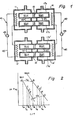
- a heat pump unit composed of a first heat medium receptacle 11, a second heat medium receptacle 14 and a plurality of closed vessels 17A, 17B,... is disposed in juxtaposition with another heat pump unit composed of a first heat medium receptacle 11', a second heat medium receptacle 14' anda plurality of closed vessels 17A',17B', ....
- a heat exchanging means 41 is provided between the first heat medium receptacles 11 and 11'
- a heat exchanging means 42 is provided between the second heat medium receptacles 14 and 14'.
- the heat exchanging means 41 and 42 are composed of pumps 43 and 44 and fluid (e.g., water) conduits 45 and 46, respectively.
- the heat exchange may also be carried out by simply exchanging the staying heat media between the heat medium receptacles 11 and 11' (or 14 and 14').
- the coefficient of performance can be determined from the heat balances in the individual operating steps. For simplification, let us assume that in each chamber, m moles of hydrogen react, the heats of reaction of M,H and M 2 H per mole of hydrogen are ⁇ H 1 and AH 2 , the neat capacity of each of the chambers 19 and 19' containing M,H is J 1 , and the heat capacity of each of the chambers 20 and 20' containing M Z H is J 2 .
- the chambers 19,20,19' and 20' assume the states shown by points A, B, C and D.
- M 2 H releases m moles of hydrogen in the course of changing from point B to point D, thereby absorbing heat in an amount of m ⁇ H 2 .
- Q 3 J 2 (T M -T L )
- Hydrogen released in this step enters the chamber 19' through a partitioning wall 18' and MH 1 generates heat in an amount of ⁇ H 1 , which heat is taken away by the cooler.
- the chamber 19' corresponds to the chamber 19 in step (1), and the chamber 20' to the chamber 20 in step (1).
- This step is for completing the cycle.
- the chamber 20 at ordinary temperature T L is heated to temperature T M by a heat source kept at temperature T M to release hydrogen.
- heat in an amount of J 2 (T M -T L )+m ⁇ H 2 is supplied to the chamber 20 from a heat source.
- the released hydrogen is occluded by M,H at temperature T M in the chamber 19, whereby the temperature of the chamber 19 reaches T H .
- the amount of heat supplied to the heating load is m ⁇ H 1 ⁇ J 1 (T H -T M ). Then, the chamber 20 is cooled with the atmospheric air in order to return its temperature to T L .
- the chamber 19 releases hydrogen to M 2 H at temperature T L and attains temperature T M . If the heat generated by the hydrogen occlusion of M 2 H is taken away by the atmospheric air, the amount of heat required for this operation is m ⁇ H 1 ⁇ J 1 (T H ⁇ T M ). Since the chambers 19' and 20' repeat the above operation with a phase deviation of a half cycle, the coefficient of performance COP H of this device is given by the following equation.
- the coefficient of performance of the device is determined in the following manner.
- the chamber 19' is heated by means of the heat medium receptacle 11' and kept at temperature T H , and the chamber 19 is cooled to temperature T M by the heat medium receptacle 11.
- the heating and cooling of the chambers are stopped, and a pump 43 in a heat exchanging circuit 45 is driven to perform heat exchange between the chambers 19 and 19'.
- the chamber 19 is heated to temperature T F
- the chamber 19' is cooled to temperature T E .
- M 1 H in the chamber 19 changes from point C to point F
- M 1 H in the chamber 19' from point A to point E.
- T o in Figure 2 is the temperature which the chambers 20 and 20' would have if heat exchange has been performed completely between these chambers, and point O' represents the state of M 2 H corresponding to this temperature.
- T E , To, T F , T G , To, and T K the value of this equation means the heat exchanging efficiency of the heat exchangers 41 and 42.
- the chambers 20' endothermically releases m moles of hydrogen and absorbs heat in an amount of mAH 2 , as stated hereinabove.
- the chambers 20' themselves absorb heat in an amount of J 2 (T G -T L ) and attain the temperature T L , these chambers take away heat in an amount of
- the proportion of the heat capacities of the chambers in the coefficient of performance is reduced by one-half of ⁇ as compared with the case of not using them.
- the coefficient of performance increases markedly.
- a compressor (not shown in Figure 1) which pressurizes hydrogen gas in one of the first and second chambers which communicate with each other and reduces the pressure of hydrogen gas in the other is used as a means for moving hydrogen between the first and second chambers.
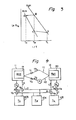
- FIG. 4 One example of a heat pump assembly including such a compressor is diagrammatically shown in Figure 4.
- the first chamber 19 and the second chamber 20 are connected by means of an ordinary communicating pipe 111 and a communicating pipe 112 equipped with a compressor P l .
- V, and V 2 represent values for the communicating pipes 111 and 112, respectively.
- Heat exchange between the chambers 19 and 20 is performed by means of heat media 103, 104 and 105 maintained at temperatures T H , T M and T L respectively.
- V 3 , V 4 , V s and V 6 respectively represent valves for the heat media.
- P 3 and P 4 represent pumps for the heat media.
- FIG 4 is a simplified view and each of the chambers 19 and 20 in fact represents a plurality of chambers, and a plurality of chambers 19 and a plurality of chambers 20 are located within separate heat medium receptacles. While flowing through the heat medium receptacles, the heat media 103, 104 and 105 exchange heat with M,H of the chambers 19 or M 2 H of the chambers 20 through the walls of the chambers 19 or 20.
- the communicating pipe 111 is used to return hydrogen residing deviatingly in one of the chambers, and the heat medium 104 (e.g., to be supplied from the outer atmosphere) can be used to cool or heat the closed vessels and the heat medium receptacles when hydrogen transfer by means of the compressor has been completed.
Landscapes
- Engineering & Computer Science (AREA)
- Physics & Mathematics (AREA)
- Mechanical Engineering (AREA)
- Thermal Sciences (AREA)
- General Engineering & Computer Science (AREA)
- Sorption Type Refrigeration Machines (AREA)
Claims (1)
- Un assemblage de pompe à chaleur à hydrure métallique comprenant une première et une seconde unité de pompe à chaleur, chacune desdites unités de pompe comprenant un premier récipient de fluide thermique (11, 11'), présentant dans celui-ci un écoulement de fluide thermique, un second récipient de fluide thermique (14, 14') présentant dans celui-ci un écoulement de fluide thermique, et au moins une curve fermée (17a, 17b; 17a', 17b') contenant une atmosphère d'hydrogène gazeux et divisée en une première chambre (19, 19') contenant un premier hydrure métallique (H,H) en son sein et une seconde chambre (20, 20') contenant un second hydrure métallique différent (H2H) en son sein, lesdites première et seconde chambres (19, 19', 20, 20') de ladite curve fermée étant conçues pour communiquer entre elles de façon à ce que l'hydrogène gazeux passe d'une chambre à l'autre mais pas les hydrures métalliques, ladite première chambre (19,19') de la cuve fermée étant située dans le premier récipient à fluide thermique (11, 11') et ladite seconde chambre (20, 20') de la cuve fermée étant située dans le second récipient à fluide thermique (14, 14'), ce qui fait que l'échange de chaleur est effectué entre les fluides thermiques dans les premier et second récipients à fluide thermique (11, 11', 14, 14') et les premier et second hydrures métalliques à travers les parois extérieures des cuves fermées, et comprenant en outre des moyens (41) pour réaliser l'échange de chaleur entre le premier récipient à fluide thermique (11) de la première unité de pompe à chaleur et le premier récipient à fluide thermique (11') de la seconde unité de pompe à chaleur, des moyens (42) pour l'échange de chaleur entre le second récipient à fluide thermique (14) de la première unité de pompe à chaleur et le second récipient à fluide thermique (14') de la seconde unité de pompe à chaleur, caractérisé en ce qu'il comprend un compresseur (P,) pour forcer l'hydrogène gazeux à passer d'une chambre (20, 20') à l'autre chambre (19, 19') dans ladite au moins une cuve fermée (17a, 17b; 17a', 17b').
Applications Claiming Priority (4)
| Application Number | Priority Date | Filing Date | Title |
|---|---|---|---|
| JP185356/80 | 1980-12-29 | ||
| JP55185356A JPS602241B2 (ja) | 1980-12-29 | 1980-12-29 | 金属水素化物装置 |
| JP7555981A JPS57188993A (en) | 1981-05-18 | 1981-05-18 | Device utilizing metal hydride |
| JP75559/81 | 1981-05-18 |
Related Parent Applications (2)
| Application Number | Title | Priority Date | Filing Date |
|---|---|---|---|
| EP81110803A Division EP0055855A3 (fr) | 1980-12-29 | 1981-12-28 | Pompe à chaleur utilisant des hydrures métalliques |
| EP81110803.4 Division | 1981-12-28 |
Publications (3)
| Publication Number | Publication Date |
|---|---|
| EP0168062A2 EP0168062A2 (fr) | 1986-01-15 |
| EP0168062A3 EP0168062A3 (en) | 1986-04-16 |
| EP0168062B1 true EP0168062B1 (fr) | 1989-10-04 |
Family
ID=26416698
Family Applications (2)
| Application Number | Title | Priority Date | Filing Date |
|---|---|---|---|
| EP85109046A Expired EP0168062B1 (fr) | 1980-12-29 | 1981-12-28 | Installation de pompe à chaleur utilisant des hydrures métalliques |
| EP81110803A Ceased EP0055855A3 (fr) | 1980-12-29 | 1981-12-28 | Pompe à chaleur utilisant des hydrures métalliques |
Family Applications After (1)
| Application Number | Title | Priority Date | Filing Date |
|---|---|---|---|
| EP81110803A Ceased EP0055855A3 (fr) | 1980-12-29 | 1981-12-28 | Pompe à chaleur utilisant des hydrures métalliques |
Country Status (2)
| Country | Link |
|---|---|
| US (1) | US4422500A (fr) |
| EP (2) | EP0168062B1 (fr) |
Cited By (4)
| Publication number | Priority date | Publication date | Assignee | Title |
|---|---|---|---|---|
| US6737180B2 (en) | 2000-04-10 | 2004-05-18 | Johnson Electro Mechanical Systems, Llc | Electrochemical conversion system |
| US6899967B2 (en) | 2000-04-10 | 2005-05-31 | Excellatron Solid State, Llc | Electrochemical conversion system |
| US7540886B2 (en) | 2005-10-11 | 2009-06-02 | Excellatron Solid State, Llc | Method of manufacturing lithium battery |
| US7943250B1 (en) | 2000-07-28 | 2011-05-17 | Johnson Research & Development Co., Inc. | Electrochemical conversion system for energy management |
Families Citing this family (37)
| Publication number | Priority date | Publication date | Assignee | Title |
|---|---|---|---|---|
| US4402915A (en) * | 1981-05-06 | 1983-09-06 | Sekisui Kagaku Kogyo Kabushiki Kaisha | Metal hydride reactor |
| DE3277930D1 (en) * | 1981-07-31 | 1988-02-11 | Seikisui Chemical Co Ltd | Metal hydride heat pump system |
| US4510759A (en) * | 1981-09-17 | 1985-04-16 | Agency Of Industrial Science & Technology | Metalhydride container and metal hydride heat storage system |
| FR2539854A1 (fr) * | 1983-04-22 | 1984-07-27 | Cetiat | Installation de refrigeration par adsorption sur un adsorbant solide et procede pour sa mise en oeuvre |
| DE3518738A1 (de) * | 1985-05-24 | 1986-11-27 | Ruhrgas Ag, 4300 Essen | Verfahren und waermepumpe zur gewinnung von nutzwaerme |
| JPS6332263A (ja) * | 1986-07-25 | 1988-02-10 | ダイキン工業株式会社 | 水素吸蔵合金を利用する補助加熱装置 |
| US5174367A (en) * | 1989-03-13 | 1992-12-29 | Sanyo Electric Co., Ltd. | Thermal utilization system using hydrogen absorbing alloys |
| US4928496A (en) * | 1989-04-14 | 1990-05-29 | Advanced Materials Corporation | Hydrogen heat pump |
| US5450721A (en) * | 1992-08-04 | 1995-09-19 | Ergenics, Inc. | Exhaust gas preheating system |
| FR2704631B1 (fr) * | 1993-04-27 | 1995-07-13 | Elf Aquitaine | Dispositif de refrigeration et de chauffage utilisant un sorbant solide. |
| US5445099A (en) * | 1993-09-20 | 1995-08-29 | Rendina; David D. | Hydrogen hydride keel |
| US5862855A (en) * | 1996-01-04 | 1999-01-26 | Balk; Sheldon | Hydride bed and heat pump |
| US5938207A (en) * | 1997-07-16 | 1999-08-17 | Stm Corporation | Heat engine rod seal system |
| US6161614A (en) * | 1998-03-27 | 2000-12-19 | Karmazin Products Corporation | Aluminum header construction |
| JP3812792B2 (ja) * | 1999-08-06 | 2006-08-23 | 株式会社豊田自動織機 | 固気反応粉粒充填間接熱交換器 |
| US6709778B2 (en) | 2000-04-10 | 2004-03-23 | Johnson Electro Mechanical Systems, Llc | Electrochemical conversion system |
| US6686076B2 (en) | 2000-04-10 | 2004-02-03 | Excellatron Solid State, Llc | Electrochemical conversion system |
| US6949303B1 (en) | 2000-04-10 | 2005-09-27 | Johnson Electro Mechanical Systems, Llc | Electromechanical conversion system |
| US6489049B1 (en) | 2000-07-03 | 2002-12-03 | Johnson Electro Mechanical Systems, Llc | Electrochemical conversion system |
| KR100842456B1 (ko) * | 2000-07-28 | 2008-07-01 | 존슨 리서치 앤드 디벨럽먼트 컴퍼니, 인코포레이티드 | 역방향 사이클에서 작동가능한 엔진 |
| US20070094865A1 (en) * | 2002-01-10 | 2007-05-03 | Ji-Guang Zhang | Packaged thin film batteries and methods of packaging thin film batteries |
| US7960054B2 (en) * | 2002-01-10 | 2011-06-14 | Excellatron Solid State Llc | Packaged thin film batteries |
| US20080229766A1 (en) * | 2004-01-28 | 2008-09-25 | Commonwealth Scientific And Industrial Research Organisation | Method, Apparatus and System for Transferring Heat |
| US20080070087A1 (en) * | 2004-02-20 | 2008-03-20 | Excellatron Solid State, Llc | Non-volatile cathodes for lithium oxygen batteries and method of producing same |
| US7731765B2 (en) | 2004-02-20 | 2010-06-08 | Excellatron Solid State, Llc | Air battery and manufacturing method |
| US10566669B2 (en) | 2004-02-20 | 2020-02-18 | Johnson Ip Holding, Llc | Lithium oxygen batteries having a carbon cloth current collector and method of producing same |
| US7901730B2 (en) * | 2004-04-26 | 2011-03-08 | Johnson Research & Development Co., Inc. | Thin film ceramic proton conducting electrolyte |
| US20050274492A1 (en) * | 2004-06-10 | 2005-12-15 | Hera Usa Inc. | Metal hydride based vehicular exhaust cooler |
| US8568921B1 (en) | 2004-08-18 | 2013-10-29 | Excellatron Solid State Llc | Regenerative ion exchange fuel cell |
| US7213409B1 (en) * | 2005-07-14 | 2007-05-08 | The United States Of America As Represented By The Secretary Of The Navy | Reconfigurable hydrogen transfer heating/cooling system |
| CN100404976C (zh) * | 2006-07-13 | 2008-07-23 | 上海交通大学 | 单合金压缩-扩散式金属氢化物制热/制冷方法及系统 |
| WO2009117496A2 (fr) * | 2008-03-20 | 2009-09-24 | Excellatron Solid State, Llc | Système de batterie à oxygène |
| US8286837B1 (en) * | 2008-07-14 | 2012-10-16 | William Sydney Blake | One turn actuated duration dual mechanism spray dispenser pump |
| JP6674378B2 (ja) * | 2014-11-10 | 2020-04-01 | 日本碍子株式会社 | 蓄熱材を収容する容器 |
| WO2016151416A1 (fr) * | 2015-03-25 | 2016-09-29 | Thermax Limited | Pompe à chaleur à hydrure métallique fournissant une sortie uniforme continue |
| WO2017017548A1 (fr) * | 2015-07-30 | 2017-02-02 | Thermax Limited | Système de régénération pour une pompe de chaleur à hydrure métallique |
| SE547067C2 (en) * | 2022-11-25 | 2025-04-15 | Texel Energy Storage Ab | Energy storage device comprising hydride material, system, and method |
Citations (1)
| Publication number | Priority date | Publication date | Assignee | Title |
|---|---|---|---|---|
| US4039023A (en) * | 1976-02-25 | 1977-08-02 | The United States Of America As Represented By The Secretary Of The Navy | Method and apparatus for heat transfer, using metal hydrides |
Family Cites Families (20)
| Publication number | Priority date | Publication date | Assignee | Title |
|---|---|---|---|---|
| US1506531A (en) * | 1921-12-12 | 1924-08-26 | Westinghouse Electric & Mfg Co | Refrigeration apparatus |
| DE2501250A1 (de) * | 1975-01-14 | 1976-07-15 | Siemens Ag | Verfahren zum betrieb einer brennkraftmaschine |
| US4161211A (en) * | 1975-06-30 | 1979-07-17 | International Harvester Company | Methods of and apparatus for energy storage and utilization |
| JPS5231995A (en) * | 1975-09-08 | 1977-03-10 | Nissan Motor Co Ltd | Gas generator |
| US4044819A (en) * | 1976-02-12 | 1977-08-30 | The United States Of America As Represented By The United States Energy Research And Development Administration | Hydride heat pump |
| NL7601906A (nl) * | 1976-02-25 | 1977-08-29 | Philips Nv | Cyclische desorptiekoelmachine resp. - warmte- pomp. |
| CH609140A5 (fr) * | 1976-05-18 | 1979-02-15 | Sulzer Ag | |
| US4046522A (en) * | 1976-06-25 | 1977-09-06 | Mobil Oil Corporation | Pre-engine converter for use with fuels containing oxygenated compounds |
| GB1581639A (en) * | 1976-08-13 | 1980-12-17 | Johnson Matthey Co Ltd | Storage of gas |
| US4055962A (en) * | 1976-08-18 | 1977-11-01 | Terry Lynn E | Hydrogen-hydride absorption systems and methods for refrigeration and heat pump cycles |
| US4091086A (en) * | 1976-12-20 | 1978-05-23 | Engelhard Minerals & Chemicals Corporation | Process for production of hydrogen |
| US4200144A (en) * | 1977-06-02 | 1980-04-29 | Standard Oil Company (Indiana) | Hydride heat pump |
| CA1127857A (fr) * | 1977-09-30 | 1982-07-20 | Lynn E. Terry | Systemes et methodes d'absorption par hydrogene amphotere pour cycles frigorifiques et pompes de chaleur |
| DE2906642A1 (de) * | 1978-02-24 | 1979-08-30 | Mpd Technology | Druckgasbehaelter |
| DE2808876A1 (de) * | 1978-03-02 | 1979-09-13 | Heidenheimer Waermevertriebs G | Waerme/kaeltewandler-kombination auf der basis von wasserstoffhydrid |
| US4199952A (en) * | 1978-10-10 | 1980-04-29 | Owens-Illinois, Inc. | Modular solar powered heat pump |
| US4282835A (en) * | 1979-07-02 | 1981-08-11 | Wm. D. Peterson & Associates | Internal combustion engine with gas synthesizer |
| DE2938203A1 (de) * | 1979-09-21 | 1981-04-02 | Knoche, Karl-Friedrich, Prof. Dr.-Ing., 5100 Aachen | Verfahren und vorrichtung zur nutzung von bei niedriger temperatur aufgenommener waerme |
| DE3020565A1 (de) * | 1980-05-30 | 1981-12-10 | Studiengesellschaft Kohle mbH, 4330 Mülheim | Verfahren und vorrichtung zur energiesparenden gewinnung von nutzwaerme aus der umgebung oder aus abfallwaerme |
| US4372376A (en) * | 1980-12-09 | 1983-02-08 | The United States Of America As Represented By The United States Department Of Energy | Heat pump apparatus |
-
1981
- 1981-12-23 US US06/333,680 patent/US4422500A/en not_active Expired - Fee Related
- 1981-12-28 EP EP85109046A patent/EP0168062B1/fr not_active Expired
- 1981-12-28 EP EP81110803A patent/EP0055855A3/fr not_active Ceased
Patent Citations (1)
| Publication number | Priority date | Publication date | Assignee | Title |
|---|---|---|---|---|
| US4039023A (en) * | 1976-02-25 | 1977-08-02 | The United States Of America As Represented By The Secretary Of The Navy | Method and apparatus for heat transfer, using metal hydrides |
Cited By (4)
| Publication number | Priority date | Publication date | Assignee | Title |
|---|---|---|---|---|
| US6737180B2 (en) | 2000-04-10 | 2004-05-18 | Johnson Electro Mechanical Systems, Llc | Electrochemical conversion system |
| US6899967B2 (en) | 2000-04-10 | 2005-05-31 | Excellatron Solid State, Llc | Electrochemical conversion system |
| US7943250B1 (en) | 2000-07-28 | 2011-05-17 | Johnson Research & Development Co., Inc. | Electrochemical conversion system for energy management |
| US7540886B2 (en) | 2005-10-11 | 2009-06-02 | Excellatron Solid State, Llc | Method of manufacturing lithium battery |
Also Published As
| Publication number | Publication date |
|---|---|
| US4422500A (en) | 1983-12-27 |
| EP0055855A3 (fr) | 1982-12-08 |
| EP0055855A2 (fr) | 1982-07-14 |
| EP0168062A3 (en) | 1986-04-16 |
| EP0168062A2 (fr) | 1986-01-15 |
Similar Documents
| Publication | Publication Date | Title |
|---|---|---|
| US4422500A (en) | Metal hydride heat pump | |
| EP0071271B1 (fr) | Système de pompe à chaleur utilisant des hydrures métalliques | |
| EP0053737B1 (fr) | Dispositif de pompe à chaleur | |
| EP0388132B1 (fr) | Système de mobilisation thermique utilisant des alliages absorbant l'hydrogène | |
| US5351493A (en) | Thermally driven refrigeration system utilizing metal hydrides | |
| JP3126086B2 (ja) | 圧縮式金属水素化物ヒートポンプ | |
| JP2000121197A (ja) | ヒートポンプ及びその運転方法 | |
| US5048299A (en) | Air conditioner for an automobile | |
| JPH0121432B2 (fr) | ||
| JPS6241138B2 (fr) | ||
| JPS6329182B2 (fr) | ||
| JPS6329183B2 (fr) | ||
| JP2643235B2 (ja) | メタルハイドライド加熱冷却装置 | |
| JPH085173A (ja) | パルスチューブ冷凍機 | |
| JPS638394B2 (fr) | ||
| JPH07243717A (ja) | 水素吸蔵合金ヒートポンプ | |
| JPH0634230A (ja) | 冷熱発生装置 | |
| JP3133442B2 (ja) | 金属水素化物を利用した熱駆動型冷熱発生方法および装置 | |
| JPS6037395B2 (ja) | 携帯用加熱又は冷却装置 | |
| JPS6329181B2 (fr) | ||
| JPH02306068A (ja) | 金属水素化物を用いた車用冷却装置 | |
| JP3133440B2 (ja) | 金属水素化物を利用した熱駆動型冷熱発生方法及び装置 | |
| JPS6096801A (ja) | 蒸気発生装置 | |
| JPH06323685A (ja) | 冷熱発生方法および冷熱発生装置 | |
| JPH0399170A (ja) | 金属水素化物を利用した冷却装置 |
Legal Events
| Date | Code | Title | Description |
|---|---|---|---|
| PUAI | Public reference made under article 153(3) epc to a published international application that has entered the european phase |
Free format text: ORIGINAL CODE: 0009012 |
|
| AC | Divisional application: reference to earlier application |
Ref document number: 55855 Country of ref document: EP |
|
| AK | Designated contracting states |
Designated state(s): DE FR GB IT NL |
|
| PUAL | Search report despatched |
Free format text: ORIGINAL CODE: 0009013 |
|
| RIN1 | Information on inventor provided before grant (corrected) |
Inventor name: NAKATA, YASUSHI Inventor name: YAMAJI, KATUHIKO Inventor name: YOSHIDA, KEN Inventor name: MIYAMOTO, KAZUAKI Inventor name: MIYAMOTO, MINORU Inventor name: NISHIZAKI, TOMOYOSHI |
|
| AK | Designated contracting states |
Kind code of ref document: A3 Designated state(s): DE FR GB IT NL |
|
| 17P | Request for examination filed |
Effective date: 19860918 |
|
| 17Q | First examination report despatched |
Effective date: 19870220 |
|
| GRAA | (expected) grant |
Free format text: ORIGINAL CODE: 0009210 |
|
| AC | Divisional application: reference to earlier application |
Ref document number: 55855 Country of ref document: EP |
|
| AK | Designated contracting states |
Kind code of ref document: B1 Designated state(s): DE FR GB IT NL |
|
| ITF | It: translation for a ep patent filed | ||
| REF | Corresponds to: |
Ref document number: 3177111 Country of ref document: DE Date of ref document: 19891109 |
|
| ET | Fr: translation filed | ||
| PLBE | No opposition filed within time limit |
Free format text: ORIGINAL CODE: 0009261 |
|
| STAA | Information on the status of an ep patent application or granted ep patent |
Free format text: STATUS: NO OPPOSITION FILED WITHIN TIME LIMIT |
|
| 26N | No opposition filed | ||
| ITTA | It: last paid annual fee | ||
| PGFP | Annual fee paid to national office [announced via postgrant information from national office to epo] |
Ref country code: NL Payment date: 19931231 Year of fee payment: 13 |
|
| PGFP | Annual fee paid to national office [announced via postgrant information from national office to epo] |
Ref country code: FR Payment date: 19941209 Year of fee payment: 14 |
|
| PGFP | Annual fee paid to national office [announced via postgrant information from national office to epo] |
Ref country code: GB Payment date: 19941220 Year of fee payment: 14 |
|
| PGFP | Annual fee paid to national office [announced via postgrant information from national office to epo] |
Ref country code: DE Payment date: 19941222 Year of fee payment: 14 |
|
| PG25 | Lapsed in a contracting state [announced via postgrant information from national office to epo] |
Ref country code: NL Effective date: 19950701 |
|
| NLV4 | Nl: lapsed or anulled due to non-payment of the annual fee |
Effective date: 19950701 |
|
| PG25 | Lapsed in a contracting state [announced via postgrant information from national office to epo] |
Ref country code: GB Effective date: 19951228 |
|
| GBPC | Gb: european patent ceased through non-payment of renewal fee |
Effective date: 19951228 |
|
| PG25 | Lapsed in a contracting state [announced via postgrant information from national office to epo] |
Ref country code: FR Effective date: 19960830 |
|
| PG25 | Lapsed in a contracting state [announced via postgrant information from national office to epo] |
Ref country code: DE Effective date: 19960903 |
|
| REG | Reference to a national code |
Ref country code: FR Ref legal event code: ST |