EP0168153A2 - Kurbelwelle für einen Verbrennungsmotor - Google Patents
Kurbelwelle für einen Verbrennungsmotor Download PDFInfo
- Publication number
- EP0168153A2 EP0168153A2 EP85303835A EP85303835A EP0168153A2 EP 0168153 A2 EP0168153 A2 EP 0168153A2 EP 85303835 A EP85303835 A EP 85303835A EP 85303835 A EP85303835 A EP 85303835A EP 0168153 A2 EP0168153 A2 EP 0168153A2
- Authority
- EP
- European Patent Office
- Prior art keywords
- crankshaft
- main
- flywheel
- groove
- journal
- Prior art date
- Legal status (The legal status is an assumption and is not a legal conclusion. Google has not performed a legal analysis and makes no representation as to the accuracy of the status listed.)
- Pending
Links
Images



Classifications
-
- F—MECHANICAL ENGINEERING; LIGHTING; HEATING; WEAPONS; BLASTING
- F16—ENGINEERING ELEMENTS AND UNITS; GENERAL MEASURES FOR PRODUCING AND MAINTAINING EFFECTIVE FUNCTIONING OF MACHINES OR INSTALLATIONS; THERMAL INSULATION IN GENERAL
- F16C—SHAFTS; FLEXIBLE SHAFTS; ELEMENTS OR CRANKSHAFT MECHANISMS; ROTARY BODIES OTHER THAN GEARING ELEMENTS; BEARINGS
- F16C3/00—Shafts; Axles; Cranks; Eccentrics
- F16C3/04—Crankshafts, eccentric-shafts; Cranks, eccentrics
- F16C3/06—Crankshafts
-
- F—MECHANICAL ENGINEERING; LIGHTING; HEATING; WEAPONS; BLASTING
- F16—ENGINEERING ELEMENTS AND UNITS; GENERAL MEASURES FOR PRODUCING AND MAINTAINING EFFECTIVE FUNCTIONING OF MACHINES OR INSTALLATIONS; THERMAL INSULATION IN GENERAL
- F16C—SHAFTS; FLEXIBLE SHAFTS; ELEMENTS OR CRANKSHAFT MECHANISMS; ROTARY BODIES OTHER THAN GEARING ELEMENTS; BEARINGS
- F16C2360/00—Engines or pumps
- F16C2360/22—Internal combustion engines
Definitions
- the present invention relates to a crankshaft for an internal combustion engine.
- a crankshaft a comprises crank arms e and h, connecting-rod journals (crankpin) f and g, and a main-bearing journal d which is connected to a flywheel b.
- crankshaft a of a four-cylinder in-line engine for example, crank arm e of the fourth cylinder adjacent to the flywheel b, connecting-rod journal f, crank arm h, and connecting-rod journal g of the third cylinder are deflected by the force as shown by the broken line E in Figure 4a.
- the bending of the crankshaft is schematically indicated in Figure 4b by a broken line C in relation to the axis of the crankshaft shown by a broken line D. It will be seen that the crankshaft is bent at a point B. In other words, at the point B, which is the juncture of the fourth connecting-rod journal f and the crank arm e, stress concentration occurs.
- the present invention seeks to provide a crankshaft which may overcome the above-mentioned problems and improve the fatigue limit and the strength of the crankshaft.
- the present invention provides a crankshaft for connection by an end to a flywheel in an internal combustion engine, the crankshaft having a main-bearing journal at the end where the crankshaft and flywheel connect, and characterised by a groove at the periphery of the main-bearing journal, whereby when the crankshaft is subject to a bending force the shaft can flex at the groove.
- a plurality of arcuate grooves are formed on the main-bearing journal.
- a crankshaft of a four-cylinder in-line combustion engine generally indicated by the numeral 1 has a flywheel 6 secured thereto at an output end, and a drive pulley 7 mounted on the other end thereof.
- the crankshaft 1 is supported at a first main-bearing journal 21, second main-bearing journal 22, and a third main-bearing journal 23 by main bearings 91, 92 and 93 provided in bulkheads 81, 82 and 83.
- a first connecting-rod journal 31, second connecting-rod journal 32, third connecting-rod journal 33 and fourth connecting-rod journal 34 are formed on the crankshaft at ends of crank arms 41 to 46, respectively.
- annular groove 5 formed on the periphery of the third main-bearing journal 23 adjacent to the flywheel 6 is an annular groove 5, the inside diameter of which is made to maintain sufficient strength in the crankshaft.
- the bottom of the groove 5 has an arcuate portion in longitudinal section of the main-bearing journal 23.
- crankshaft 1 constructed as explained above will now be explained.
- a crankshaft having the heavy flywheel at its output end may be subject to great stresses at the point B of Figure 4a. In the embodiment of the present invention, such stresses are diverged by the function of the annular groove 5.
- crankshaft is bent at the point F and the deflection is shown by line C' (broken line) with respect to the axis D of the crankshaft (a chain line).
- line C' broken line
- the stresses conventionally concentrated at the point B of the crankshaft is now divided between two positions, i.e. the point B and the point F by the provision of the annular groove 5.
- the stress at the juncture B is reduced compared with the conventional crankshaft, so that the fatigue limit at the point B is improved.
- the third main-bearing journal 23 is made sufficiently strong despite the annular groove 5, the strength and rigidity of the crankshaft is maintained.
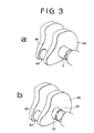
- annular groove 5 is formed on the whole of the periphery of the third main-bearing journal 23 in the first embodiment of the present invention, a plurality of arcuate grooves 51 and 52 may be provided as shown in Figure 3b, so as to divert the stress at the juncture B.
- the present invention provides a crankshaft having, at an end adjacent a flywheel, a journal provided with an annular groove so as to diverge stresses.
- the crankshaft of the present invention can be employed in an engine having large torque and large output.
- the crankshaft can be made light in weight and simple in construction.
Landscapes
- Engineering & Computer Science (AREA)
- General Engineering & Computer Science (AREA)
- Ocean & Marine Engineering (AREA)
- Mechanical Engineering (AREA)
- Shafts, Cranks, Connecting Bars, And Related Bearings (AREA)
- Cylinder Crankcases Of Internal Combustion Engines (AREA)
Applications Claiming Priority (2)
| Application Number | Priority Date | Filing Date | Title |
|---|---|---|---|
| JP59141758A JPS6121413A (ja) | 1984-07-09 | 1984-07-09 | 内燃機関のクランク軸 |
| JP141758/84 | 1984-07-09 |
Publications (2)
| Publication Number | Publication Date |
|---|---|
| EP0168153A2 true EP0168153A2 (de) | 1986-01-15 |
| EP0168153A3 EP0168153A3 (de) | 1986-12-30 |
Family
ID=15299504
Family Applications (1)
| Application Number | Title | Priority Date | Filing Date |
|---|---|---|---|
| EP85303835A Pending EP0168153A3 (de) | 1984-07-09 | 1985-05-30 | Kurbelwelle für einen Verbrennungsmotor |
Country Status (3)
| Country | Link |
|---|---|
| EP (1) | EP0168153A3 (de) |
| JP (1) | JPS6121413A (de) |
| DE (1) | DE168153T1 (de) |
Cited By (4)
| Publication number | Priority date | Publication date | Assignee | Title |
|---|---|---|---|---|
| FR2847314A1 (fr) * | 2002-11-14 | 2004-05-21 | Renault Sa | Vilebrequin de moteur a combustion interne, notamment de vehicule automobile |
| FR2885187A1 (fr) * | 2005-04-28 | 2006-11-03 | Renault Sas | Vilebrequin avec gorge permettant de reduire les contraintes, notamment de vehicule automobile |
| EP2730791A1 (de) * | 2012-11-09 | 2014-05-14 | MAN Diesel & Turbo, filal af MAN Diesel & Turbo SE, Tyskland | Kurbelwellenlageranordnung und großer mehrzylindriger Zweitaktdieselmotor |
| US20150247525A1 (en) * | 2012-09-24 | 2015-09-03 | Thyssenkrupp Matalúrgica Campo Limpo Ltda. | Weight optimized crank-shaft |
Families Citing this family (1)
| Publication number | Priority date | Publication date | Assignee | Title |
|---|---|---|---|---|
| CN106514161B (zh) * | 2016-11-04 | 2018-09-11 | 安徽江淮汽车集团股份有限公司 | 发动机曲轴的加工方法及发动机曲轴 |
Family Cites Families (1)
| Publication number | Priority date | Publication date | Assignee | Title |
|---|---|---|---|---|
| FR799099A (fr) * | 1935-03-01 | 1936-06-05 | Anciens Etablissements Panhard | Perfectionnement aux arbres manivelles de moteurs à combustion interne |
-
1984
- 1984-07-09 JP JP59141758A patent/JPS6121413A/ja active Pending
-
1985
- 1985-05-30 DE DE198585303835T patent/DE168153T1/de active Pending
- 1985-05-30 EP EP85303835A patent/EP0168153A3/de active Pending
Cited By (6)
| Publication number | Priority date | Publication date | Assignee | Title |
|---|---|---|---|---|
| FR2847314A1 (fr) * | 2002-11-14 | 2004-05-21 | Renault Sa | Vilebrequin de moteur a combustion interne, notamment de vehicule automobile |
| FR2885187A1 (fr) * | 2005-04-28 | 2006-11-03 | Renault Sas | Vilebrequin avec gorge permettant de reduire les contraintes, notamment de vehicule automobile |
| US20150247525A1 (en) * | 2012-09-24 | 2015-09-03 | Thyssenkrupp Matalúrgica Campo Limpo Ltda. | Weight optimized crank-shaft |
| EP2730791A1 (de) * | 2012-11-09 | 2014-05-14 | MAN Diesel & Turbo, filal af MAN Diesel & Turbo SE, Tyskland | Kurbelwellenlageranordnung und großer mehrzylindriger Zweitaktdieselmotor |
| CN103807282A (zh) * | 2012-11-09 | 2014-05-21 | 曼柴油机欧洲股份公司曼柴油机德国分公司 | 曲轴、轴承组件以及大型多缸体二冲程柴油机 |
| CN103807282B (zh) * | 2012-11-09 | 2015-10-28 | 曼柴油机欧洲股份公司曼柴油机德国分公司 | 曲轴、轴承组件以及大型多缸体二冲程柴油机 |
Also Published As
| Publication number | Publication date |
|---|---|
| JPS6121413A (ja) | 1986-01-30 |
| DE168153T1 (de) | 1986-04-30 |
| EP0168153A3 (de) | 1986-12-30 |
Similar Documents
| Publication | Publication Date | Title |
|---|---|---|
| US4463550A (en) | Silent chain | |
| GB2167493A (en) | Mounting i.c. engine cylinder block crankshaft bearings | |
| US4901692A (en) | Engine and low vibration crankshaft therefor | |
| US5560333A (en) | Internal combustion engine connecting rod | |
| US5857388A (en) | Balance shafts having minimal mass | |
| US4015485A (en) | Crank shaft for a multi-cylinder short stroke internal combustion engine | |
| EP0168153A2 (de) | Kurbelwelle für einen Verbrennungsmotor | |
| US5014572A (en) | Assembled crankshaft | |
| GB2190169A (en) | Power transmission belt | |
| KR100941204B1 (ko) | V형 내연기관용 크랭크샤프트 | |
| US7273030B2 (en) | Crankshaft support structure of internal combustion engine | |
| KR100310085B1 (ko) | 2행정v-엔진용크로스헤드 | |
| US4622932A (en) | V-crankarm | |
| KR102201465B1 (ko) | 실린더 블록 조립체 | |
| JPH08226432A (ja) | クランク軸 | |
| EP0679229B1 (de) | Kurbelwelle für eine zweitakt-brennkraftmaschine und verfahren zur einstellung derselben | |
| SU699249A1 (ru) | Подшипниковый узел кривошипной головки шатуна | |
| US4708106A (en) | Acute angle crankarm transmitting reciprocating motion in a rotary fashion | |
| US9803685B2 (en) | Crankshaft | |
| JP7425234B2 (ja) | 大型ターボ過給式2ストロークユニフロークロスヘッド内燃機関用クランクシャフト | |
| JP3460296B2 (ja) | コネクティングロッド | |
| JPH0435565Y2 (de) | ||
| KR960011922B1 (ko) | V형 6기통엔진의 크랭크샤프트 | |
| GB2342695A (en) | Balance shaft, eg for engines, with recessed cross-section | |
| JPH0794848B2 (ja) | 多気筒エンジンのクランクシヤフト |
Legal Events
| Date | Code | Title | Description |
|---|---|---|---|
| PUAI | Public reference made under article 153(3) epc to a published international application that has entered the european phase |
Free format text: ORIGINAL CODE: 0009012 |
|
| 17P | Request for examination filed |
Effective date: 19850614 |
|
| AK | Designated contracting states |
Designated state(s): DE GB |
|
| DET | De: translation of patent claims | ||
| PUAL | Search report despatched |
Free format text: ORIGINAL CODE: 0009013 |
|
| AK | Designated contracting states |
Kind code of ref document: A3 Designated state(s): DE GB |
|
| STAA | Information on the status of an ep patent application or granted ep patent |
Free format text: STATUS: EXAMINATION IS IN PROGRESS |
|
| 17Q | First examination report despatched |
Effective date: 19880804 |
|
| RIN1 | Information on inventor provided before grant (corrected) |
Inventor name: OZAWA, MASAHIRO Inventor name: MATSUNAGA, SEIKI Inventor name: TAYAMA, MASAHIRO |