EP0168223B1 - Accouplement rapide - Google Patents
Accouplement rapide Download PDFInfo
- Publication number
- EP0168223B1 EP0168223B1 EP85304804A EP85304804A EP0168223B1 EP 0168223 B1 EP0168223 B1 EP 0168223B1 EP 85304804 A EP85304804 A EP 85304804A EP 85304804 A EP85304804 A EP 85304804A EP 0168223 B1 EP0168223 B1 EP 0168223B1
- Authority
- EP
- European Patent Office
- Prior art keywords
- ring
- coupling
- open groove
- groove
- female component
- Prior art date
- Legal status (The legal status is an assumption and is not a legal conclusion. Google has not performed a legal analysis and makes no representation as to the accuracy of the status listed.)
- Expired
Links
- 230000008878 coupling Effects 0.000 title claims description 54
- 238000010168 coupling process Methods 0.000 title claims description 54
- 238000005859 coupling reaction Methods 0.000 title claims description 54
- 239000004519 grease Substances 0.000 claims description 31
- 238000000034 method Methods 0.000 claims description 11
- 238000003780 insertion Methods 0.000 claims description 6
- 230000037431 insertion Effects 0.000 claims description 6
- 239000010687 lubricating oil Substances 0.000 claims 1
- 210000002445 nipple Anatomy 0.000 description 52
- 239000000314 lubricant Substances 0.000 description 4
- 239000012530 fluid Substances 0.000 description 3
- 238000004519 manufacturing process Methods 0.000 description 3
- 239000002184 metal Substances 0.000 description 3
- 238000005520 cutting process Methods 0.000 description 2
- 235000019271 petrolatum Nutrition 0.000 description 2
- 238000010276 construction Methods 0.000 description 1
- 230000000694 effects Effects 0.000 description 1
- 230000005484 gravity Effects 0.000 description 1
- 239000007788 liquid Substances 0.000 description 1
- 230000001050 lubricating effect Effects 0.000 description 1
- 238000003754 machining Methods 0.000 description 1
- 239000000463 material Substances 0.000 description 1
- 239000000203 mixture Substances 0.000 description 1
- 229910001220 stainless steel Inorganic materials 0.000 description 1
- 239000010935 stainless steel Substances 0.000 description 1
Images
Classifications
-
- F—MECHANICAL ENGINEERING; LIGHTING; HEATING; WEAPONS; BLASTING
- F16—ENGINEERING ELEMENTS AND UNITS; GENERAL MEASURES FOR PRODUCING AND MAINTAINING EFFECTIVE FUNCTIONING OF MACHINES OR INSTALLATIONS; THERMAL INSULATION IN GENERAL
- F16L—PIPES; JOINTS OR FITTINGS FOR PIPES; SUPPORTS FOR PIPES, CABLES OR PROTECTIVE TUBING; MEANS FOR THERMAL INSULATION IN GENERAL
- F16L37/00—Couplings of the quick-acting type
- F16L37/08—Couplings of the quick-acting type in which the connection between abutting or axially overlapping ends is maintained by locking members
- F16L37/084—Couplings of the quick-acting type in which the connection between abutting or axially overlapping ends is maintained by locking members combined with automatic locking
- F16L37/088—Couplings of the quick-acting type in which the connection between abutting or axially overlapping ends is maintained by locking members combined with automatic locking by means of a split elastic ring
-
- F—MECHANICAL ENGINEERING; LIGHTING; HEATING; WEAPONS; BLASTING
- F16—ENGINEERING ELEMENTS AND UNITS; GENERAL MEASURES FOR PRODUCING AND MAINTAINING EFFECTIVE FUNCTIONING OF MACHINES OR INSTALLATIONS; THERMAL INSULATION IN GENERAL
- F16L—PIPES; JOINTS OR FITTINGS FOR PIPES; SUPPORTS FOR PIPES, CABLES OR PROTECTIVE TUBING; MEANS FOR THERMAL INSULATION IN GENERAL
- F16L2201/00—Special arrangements for pipe couplings
- F16L2201/80—Dust covers
-
- Y—GENERAL TAGGING OF NEW TECHNOLOGICAL DEVELOPMENTS; GENERAL TAGGING OF CROSS-SECTIONAL TECHNOLOGIES SPANNING OVER SEVERAL SECTIONS OF THE IPC; TECHNICAL SUBJECTS COVERED BY FORMER USPC CROSS-REFERENCE ART COLLECTIONS [XRACs] AND DIGESTS
- Y10—TECHNICAL SUBJECTS COVERED BY FORMER USPC
- Y10T—TECHNICAL SUBJECTS COVERED BY FORMER US CLASSIFICATION
- Y10T29/00—Metal working
- Y10T29/49—Method of mechanical manufacture
- Y10T29/49826—Assembling or joining
- Y10T29/49863—Assembling or joining with prestressing of part
- Y10T29/49876—Assembling or joining with prestressing of part by snap fit
-
- Y—GENERAL TAGGING OF NEW TECHNOLOGICAL DEVELOPMENTS; GENERAL TAGGING OF CROSS-SECTIONAL TECHNOLOGIES SPANNING OVER SEVERAL SECTIONS OF THE IPC; TECHNICAL SUBJECTS COVERED BY FORMER USPC CROSS-REFERENCE ART COLLECTIONS [XRACs] AND DIGESTS
- Y10—TECHNICAL SUBJECTS COVERED BY FORMER USPC
- Y10T—TECHNICAL SUBJECTS COVERED BY FORMER US CLASSIFICATION
- Y10T403/00—Joints and connections
- Y10T403/16—Joints and connections with adjunctive protector, broken parts retainer, repair, assembly or disassembly feature
- Y10T403/1608—Holding means or protector functioning only during transportation, assembly or disassembly
-
- Y—GENERAL TAGGING OF NEW TECHNOLOGICAL DEVELOPMENTS; GENERAL TAGGING OF CROSS-SECTIONAL TECHNOLOGIES SPANNING OVER SEVERAL SECTIONS OF THE IPC; TECHNICAL SUBJECTS COVERED BY FORMER USPC CROSS-REFERENCE ART COLLECTIONS [XRACs] AND DIGESTS
- Y10—TECHNICAL SUBJECTS COVERED BY FORMER USPC
- Y10T—TECHNICAL SUBJECTS COVERED BY FORMER US CLASSIFICATION
- Y10T403/00—Joints and connections
- Y10T403/60—Biased catch or latch
Definitions
- the snap ring Prior to the assembly of the two parts, the snap ring is loosely positioned in the lock groove of the outer socket.
- the forward end of the nipple passes through and expands the snap ring, and the assembly is completed when the snap ring "snaps" into the lock groove of the nipple.
- the snap ring then extends into both grooves, thereby locking the parts together.
- Couplings of this character have been used, for example, in making hydraulic connections in automobiles and trucks, such as the connections between the engine block and an oil cooler.
- An automobile or truck is constructed on a moving assembly line, and workers at stations along the line make the connections which the line is moving. It is, of course, very important, because the line moves continuously, that the socket and the nipple be securely connected together very easily and rapidly.
- a problem that has been encountered in making this connection is that, at the time the nipple is pushed into the socket, the forward end of the nipple sometimes jams or catches on the snap ring which is mounted in the interior opening of the socket.
- the snap ring is split so that it can be expanded during assembly, and the ends of the ring, which are cut during manufacture, are relatively sharp and often have burrs on them.
- the snap ring has a substantially smaller outer diameter than the maximum diameter of the groove of the socket, and consequently the snap ring may lie in the socket groove with the exposed ends of the ring in the path of the nipple during assembly. It is possible in these circumstances for the ring or the nipple or the socket to be damaged, or for extra time to be required to assemble the parts properly.
- a quick connect coupling female component comprising a receptacle means for receiving a male quick connect coupling component that is an insert means having an annular outwardly open groove in the outer surface thereof, the receptacle means having an internal opening and an annular inwardly open groove in the inner surface of the opening and being for assembling with the insert means such that in the assembled condition the insert means is positioned in the opening with the outwardly and inwardly open grooves in substantially radial alignment; the quick connect coupling female component further comprising an expandable split ring positioned in the inwardly open groove for extending between this groove and the outwardly open groove of the male component in said assembled condition; characterised in that there is a grease at least partially filling the inwardly open groove behind and around the ring, this grease being sufficiently viscous substantially to hold the ring against movement in the inwardly open groove prior to reception of the male quick connect coupling component.
- the invention also provides a quick connect coupling comprising a female component as just defined and a male component that is an insert means that can be positioned in the opening of the female component with an outwardly open groove in the outer surface of the insert means in substantial radial alignment with the inwardly open groove of the female component, and with the ring extending between the two grooves.
- the invention provides a method of positioning a split ring in a quick connect coupling female component that is for receiving a quick connect coupling male component that is an insert means having an annular outwardly open groove in the outer surface thereof, the female component being a receptacle means having an internal opening and an annular inwardly open groove in the inner surface of the opening, in which groove the ring is positioned so as to extend between this groove and the outwardly open groove of the male component in the assembled condition of the coupling;
- the method being characterised by the step of at least partially filling the inwardly open groove with a grease around the ring, this grease being sufficiently viscous substantially to hold the ring against movement in the inwardly open groove.
- the invention provides a method of constructing a quick connect coupling comprising positioning a split ring in a female component by the method as just defined, and inserting into the female coupling with the ring so positioned a male coupling comprising an insert means having an annular outwardly open groove in the outer surface thereof, this insertion being carried out so as to cause the ring to move to extend between the outwardly and inwardly open grooves.
- the grease which holds the ring in the desired position in the groove of the female component also serves as a lubricant on the ring which facilitates the assembly of the parts.
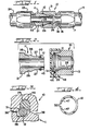
- the coupling includes an external receptacle or socket 10 that is a female component of the coupling, an internal insert or nipple 11 that is a male component of the coupling, and a snap or lock ring 12.
- the socket 10 includes a main body part 13 that has a tubular configuration and may have a hexagonal outer configuration so that it may be readily gripped by a wrench.
- the right-hand end, as seen in Figs. 1 and 2, of the socket 10 may be configured to be attached to various devices such as a metal housing, a metal tube, or a hose, for example. In the present illustration, the socket 10 is attached to a flexible hose 14.
- the right-hand end of the socket 10 has a tubular nipple 16 machined thereon, and a socket 17 is fastened to the nipple 16 as by a threaded connection indicated by the numeral 18.
- the hose 14 is tightly gripped between the nipple 16 and the socket 17 in a well known fashion.
- the nipple 11 includes a tubular body part 21 that has a hexagonal section 22 formed thereon so that it may be gripped by a wrench.
- the left-hand end, as seen in Figs. 1 and 2 may also be configured to be attached to various devices such as a housing, a tube or a hose, and in the present illustration a fitting 23 is formed on the left-hand end of the nipple 11 for attaching the nipple 11 to a flexible hose 24.
- the fitting 23 may be a conventional fitting similar to the socket 17 and the nipple 16 shown in Fig. 1.
- the socket 10 has an -internal stepped bore indicated by the numeral 26 and the nipple 11 has an external stepped outer surface indicated by the numeral 27.
- an outer ring groove 28 is formed in the outer surface of the nipple 11 and an inner ring groove 29 is formed in the bore 26 of the socket 10.
- the two grooves 28 and 29 are generally in radial alignment.
- the ring 12 is positioned in the two grooves 28 and 29 when the parts are assembled and approximately one-half the radial width of the ring 12 extends into each of the grooves 28 and 29.
- the inner nipple groove 28 has a substantially square or rectangular cross section as shown, whereas the outer socket groove 29 preferably has a curved radially enlarged bottom part.
- the outer groove 29 has the radially enlarged dimension for the purpose to be described hereinafter.
- One corner, indicated by the numeral 31 of the outer groove 29 preferably has a slanted configuration which is advantageous in that it helps to maintain the parts in assembled relation during use.
- internal pressure within the bores of the socket and the nipple tends to separate the nipple from the socket. This action tends to move the socket 10 toward the right, as seen in Figs. 1-3, relative to the nipple 11 and the slanted surface 31 wedges the ring 12 into the bottom of the inner groove 28 and thereby locks the parts tightly together.
- the ring 12 is split and it has an internal diameterthat is substantially equal to the diameter of the bottom of the inner groove 28, when the ring 12 is in its natural or unflexed state.
- the ring 12 is preferably made of a stainless steel spring material and the spring tension urges the ring 12 to the bottom of the groove 28 after the parts are assembled.
- the external diameter of the ring 12 is substantially less than the maximum diameter ofthe outer groove 29, and the purpose of this is to provide space in the outer groove 29 for the ring 12 to expand as the parts are being assembled.
- the split of the ring 12 forms a gap between the ends 32 of the ring and the gap may be formed by cutting away a section of the ring. Such a cutting action normally forms sharp edges or burrs on the ends 32, which may cause a problem as previously mentioned.
- the ring 12 Prior to assembly of the nipple 11 with the socket 10, the ring 12 is positioned in the outer groove 29 of the socket, and in prior art couplings of this nature, the ring 12 fits loosely in the groove 29.
- the stepped outer surface 27 of the nipple 11 includes an enlarged cylindrical part 36 wherein the groove 28 is formed, a reduced cylindrical part 37 at the right-hand or forward end of the nipple, and a ramped or slanted surface 38 between the surfaces 36 and 37.
- the location of the external surface 37 as the nipple 11 is being inserted into the socket 10 is indicated by the dash-dot lines 40 in Fig. 5, and it will be noted that the diameter of the surface 37 is less than the internal diameter of the ring 12.
- the diameter of the enlarged surface 36 is greater than the diameter of the ring 12 when in its normal or unflexed state, and consequently the ramp 38 engages the ring 12.
- the ramp 38 expands the ring 12 into the outer part of the groove 29 and the ring rides on the outer or enlarged surface 36 until the ring falls or snaps into the inner groove 28.
- the socket and the nipple are then of course fully and permanently assembled.
- the configuration of the bore 26 of the socket generally conforms to the outer surface 27 of the nipple 11.
- a seal groove 41 is formed in the outer surface 37 adjacent the forward end of the nipple, and an 0-ring 42 is mounted in the groove 41. As shown in Fig. 1, the 0-ring 42 engages the bore 26 of the socket 10 and forms a seal between these parts.
- the outer corner of the nipple 11, at the right-hand end, is preferably slanted or beveled as indicated at 43 to facilitate insertion of the nipple into the socket 10.
- the maximum diameter of the groove 29 is substantially greater than the outer diameter of the ring in order to provide space for the ring 12 to expand during the assembly of the parts.
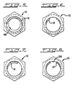
- the ring 12 prior to assembly the ring 12 is loosely positioned in the groove 29 and due to gravity forces the ring is normally offset to one side of the groove, as shown by the various positions of the ring shown in Figs. 5-7.
- a relatively viscous grease 46 which is placed in the outer groove 29 and around the ring 12, as shown in Figs. 2 and 3.
- the grease 46 may be applied during manufacture of the coupling by placing a bit of the grease on a worker's finger and wiping the grease into the groove 29, preferably after the ring 12 has been installed.
- the viscous grease holds the ring 12 in the desired position prior to assembly of the socket and the nipple, the ring being relatively centered in the groove 29 as shown in Fig. 8 and thus out of the path of the forward end of the nipple during assembly.
- a grease such as the white grease sold under the trademark Lubriplate be used because it maintains its viscous qualities even if the coupling is in a heated environment.
- another viscous fluid such as petroleum jelly, for example, were used, and if the coupling were in a relatively heated environment, such as a hot assembly factory or transportation truck, the petroleum jelly may become too liquid to hold the ring 12 in the desired position.
- the groove 29 may be entirely filled with the grease, it should be understood that this is not necessary.
- the ring has a relatively small mass, and therefore the grease is able to hold the ring in place at normal temperatures even though the socket is jarred.
- the grease serves the additional function of lubricating the ring and thus facilitating the assembly of the parts.
- the internal surface of the ring receives a film of the grease, which helps the ring 12 to slide up the ramp 38.
- the use of a lubricant has been known in the prior art for this latter function and also a lubricant on the 0-ring 40 to prevent it from tearing during assembly, but a viscous grease in the groove 29 has not been known.
- a grease such as Lubriplate
- Lubriplate is also advantageous when the coupling is used to form connections in the lubricant or oil system of an engine, because the grease is compatible with and may mix with the oil without detriment to the oil. It should be understood, however, that the 0- ring 42 normally separates the grease in the groove 29 from the internal fluid medium.
- a coupling as disclosed herein is manufactured and assembled by first mechanically forming or machining the socket and nipple parts, inserting the ring 12 into the groove 29 of the socket, and then wiping the grease into the groove and around the ring 12. It is preferred that, at the same time, the operator locates the ring at the position where the cut ends 32 of the ring are substantially close to the internal surface of the bore 26 of the socket, as illustrated in Figs. 2 and 8. This action serves both to generally center the ring and to move the sharp ends of the ring out of the path of the nipple.
- a plastic cap 48 (Fig-2) is preferably fastened on the end of the socket 10 to keep dirt out of the grease.
- the ring 12 may have a relatively short gap where the ends are shown by the solid lines, or the ring may have a larger gap where the ends are shown by the dashed lines 47.
- Fig. 5 shows the short gap whereas Figs. 6-8 show the larger gap.
- the larger gap of the ring 12 is preferable because it further facilitates the insertion of the nipple through the ring.
- the relatively short gap extends over an angle of approximately 20° whereas the larger, preferred gap has an angle of approximately 47°.
- socket and the nipple of the coupling do not have to be machined parts, as shown in Figs. 1 and 2. They may take other forms, such as mechanically formed tubular parts as shown in G.N. Vyse U.S. patent No. 3,584,902.
- a coupling as described and claimed herein has important advantages over prior art couplings.
- the socket and the nipple may be quickly and easily assembled, which is very important when they are used on assembly lines. In some assembly line connections, the worker cannot easily view the parts during assembly, and when making such "blind" connections, it is especially important that the parts be easily assembled.
- the grease that holds the snap ring in place prior to assembly also serves to lubricate the snap ring in order to facilitate assembly.
- the concept of providing grease in the snap ring groove to hold the ring in place may, of course, also be used in various types of quick-connect couplings or fittings. For example, it could be used in the type of coupling shown in the Miller U.S. patent No. 3,540,760. wherein provision is made for disassembling the coupling.
Landscapes
- Engineering & Computer Science (AREA)
- General Engineering & Computer Science (AREA)
- Mechanical Engineering (AREA)
- Quick-Acting Or Multi-Walled Pipe Joints (AREA)
Claims (11)
caractérisé en ce qu'une graisse (46) remplit au moins partiellement la gorge s'ouvrant vers l'intérieur (29), derrière la bague (12) et autour de celle-ci, cette graisse (46) étant suffisamment visqueuse pour empêcher pratiquement tout mouvement de la bague (12) dans la gorge s'ouvrant vers l'intérieur (29), avant la réception de l'élément d'accouplement mâle à branchement rapide.
Applications Claiming Priority (2)
| Application Number | Priority Date | Filing Date | Title |
|---|---|---|---|
| US06/629,060 US4565392A (en) | 1984-07-09 | 1984-07-09 | Quick connect coupling |
| US629060 | 1984-07-09 |
Publications (2)
| Publication Number | Publication Date |
|---|---|
| EP0168223A1 EP0168223A1 (fr) | 1986-01-15 |
| EP0168223B1 true EP0168223B1 (fr) | 1988-11-09 |
Family
ID=24521415
Family Applications (1)
| Application Number | Title | Priority Date | Filing Date |
|---|---|---|---|
| EP85304804A Expired EP0168223B1 (fr) | 1984-07-09 | 1985-07-05 | Accouplement rapide |
Country Status (8)
| Country | Link |
|---|---|
| US (1) | US4565392A (fr) |
| EP (1) | EP0168223B1 (fr) |
| JP (1) | JPS6145193A (fr) |
| AU (1) | AU574477B2 (fr) |
| BR (1) | BR8503255A (fr) |
| DE (1) | DE3566151D1 (fr) |
| IN (1) | IN165113B (fr) |
| ZA (1) | ZA855146B (fr) |
Families Citing this family (49)
| Publication number | Priority date | Publication date | Assignee | Title |
|---|---|---|---|---|
| US4733890A (en) * | 1984-07-09 | 1988-03-29 | Stratoflex, Inc. | Formed fluid coupling apparatus |
| FR2573834B1 (fr) * | 1984-11-29 | 1990-02-23 | Maillard Maurice Ets | Roue libre de cycle ou similaire |
| US4635966A (en) * | 1985-09-20 | 1987-01-13 | Chrysler Motors Corporation | Hose connector |
| US4783100A (en) * | 1987-04-20 | 1988-11-08 | Philips Industries, Inc. | Swivel joint |
| US4863202A (en) * | 1987-09-16 | 1989-09-05 | Oldford William G | Fluid connector assembly |
| US4906031A (en) * | 1988-07-21 | 1990-03-06 | Stratoflex, Inc. | Quick connect coupling with garter spring |
| US4872710A (en) * | 1988-10-07 | 1989-10-10 | Stratoflex, Inc. | Releasable quick connect fitting |
| AU613190B2 (en) * | 1989-05-18 | 1991-07-25 | Stratoflex Inc. | Releasable quick connect fitting |
| JPH03199798A (ja) * | 1989-12-25 | 1991-08-30 | Parker Hannifin Corp | ガータ・スプリングによる連結結合 |
| US5425558A (en) * | 1993-08-17 | 1995-06-20 | Handy & Harman Automotive Group, Inc. | Quick-connect coupling |
| US5595213A (en) * | 1995-01-04 | 1997-01-21 | Huron, Inc. | Quick connector with check valve |
| US5575180A (en) * | 1995-05-11 | 1996-11-19 | Teleflex Incorporated | Core and conduit splicer |
| US5566714A (en) * | 1995-05-24 | 1996-10-22 | Applied Power Inc. | Hydraulic coupler |
| US5685575A (en) * | 1995-11-03 | 1997-11-11 | Aeroquip Corporation | Power steering coupling assembly |
| US5658086A (en) * | 1995-11-24 | 1997-08-19 | Brokaw; Paul E. | Furniture connector |
| US5749606A (en) * | 1996-02-13 | 1998-05-12 | General Motors Corporation | Connector assembly with retainer |
| US5927975A (en) * | 1997-01-24 | 1999-07-27 | Esrock; Bernard S. | Fitting for dental syringe tip |
| US6328073B1 (en) | 1998-08-07 | 2001-12-11 | Automotive Fluid Systems, Inc. | Fluid-tight conduit connection and method of making same |
| US6450545B1 (en) | 2001-02-21 | 2002-09-17 | Parker Hennifin Corporation | Fluid coupling plug |
| PL202872B1 (pl) * | 2001-03-09 | 2009-07-31 | Gates Corp | Łącznik szybko złączny |
| US6517119B2 (en) * | 2001-03-26 | 2003-02-11 | Carrand Companies, Inc. | Hose coupling with retainer ring |
| DE10203600B4 (de) * | 2002-01-30 | 2004-12-23 | Siemens Ag | Leckageanschluss zum Anbringen einer Leckageleitung an einen Kraftstoffinjektor |
| US7681927B2 (en) * | 2002-05-10 | 2010-03-23 | Eaton Corporation | Low pressure fitting |
| US6854771B1 (en) | 2002-05-10 | 2005-02-15 | Eaton Corporation | Low pressure fitting |
| US6783462B1 (en) | 2002-05-15 | 2004-08-31 | Paul Costain | Cue stick joint |
| FR2855865B1 (fr) * | 2003-06-05 | 2006-08-04 | Montage Entretien Manutention | Dispositif pour controler l'accouplement de deux raccords de tubulures |
| US8240719B2 (en) * | 2004-07-21 | 2012-08-14 | Parker-Hannifin Corporation | Adaptor and method for converting standard tube fitting/port to push-to-connect tube fitting/port |
| US7914050B2 (en) * | 2004-07-21 | 2011-03-29 | Parker-Hannifin Corporation | Adaptor and method for converting standard tube fitting/port to push-to-connect tube fitting/port |
| US7241226B2 (en) * | 2004-10-22 | 2007-07-10 | Costain Paul D | Universal fitting for a cue stick |
| US7297068B2 (en) * | 2004-10-22 | 2007-11-20 | Costain Paul D | Vibration damping for a cue stick |
| CN101048614B (zh) * | 2004-10-29 | 2010-06-16 | 盖茨公司 | 快速连接接头和将快速连接接头的外连接部分插入到其端口中的方法 |
| EP1896760A4 (fr) * | 2005-06-27 | 2012-04-04 | Parker Hannifin Australia Pty Ltd | Accouplement pour fluide |
| US7575024B2 (en) | 2005-11-05 | 2009-08-18 | Snap-Tite Technologies, Inc. | Threaded coupling with flow shutoff |
| US7762279B2 (en) | 2005-11-05 | 2010-07-27 | Snap-Tite Technologies, Inc. | Threaded coupling with flow shutoff |
| US7601071B2 (en) * | 2006-04-21 | 2009-10-13 | Costain Paul D | Cue stick joint |
| US7540809B2 (en) * | 2006-04-21 | 2009-06-02 | Costain Paul D | Cue stick joint |
| FR2908154B1 (fr) * | 2006-11-08 | 2008-12-19 | Renault Sas | Dispositif de lubrification de turbocompresseur et procede de montage d'un tuyau de lubrication |
| US8746750B2 (en) * | 2011-02-08 | 2014-06-10 | The Gates Corporation | Variable curvature clip for quick connect coupling |
| US9700743B2 (en) | 2012-07-31 | 2017-07-11 | 3M Innovative Properties Company | Respiratory assembly including latching mechanism |
| US9364653B2 (en) | 2012-04-27 | 2016-06-14 | Colder Products Company | Aseptic coupling devices |
| US9096259B2 (en) * | 2012-07-30 | 2015-08-04 | Arvinmeritor Technology, Llc | Steering knuckle assembly with snap ring spindle retention and a method of manufacture |
| US9510626B2 (en) | 2013-02-01 | 2016-12-06 | 3M Innovative Properties Company | Sleeve-fit respirator cartridge |
| US9687328B2 (en) | 2013-05-03 | 2017-06-27 | Bernard S. Esrock | Full flow disposable syringe tip and connector |
| ITUB20152700A1 (it) * | 2015-07-31 | 2017-01-31 | Euro 2000 S R L | Raccordo componibile, particolarmente per tubazioni flessibili di protezione per cablaggi elettrici. |
| GB2542405A (en) * | 2015-09-18 | 2017-03-22 | Ford Global Tech Llc | Fluid-tight push-fit connector |
| CN106195601A (zh) * | 2016-07-29 | 2016-12-07 | 安徽江淮汽车股份有限公司 | 一种滑脂嘴安装结构 |
| US11421807B2 (en) | 2018-07-23 | 2022-08-23 | Deere & Company | Universal threadless connection |
| EP4171716A4 (fr) | 2020-06-29 | 2024-02-28 | Colder Products Company | Accouplements fluidiques aseptiques |
| TWI784475B (zh) * | 2021-04-12 | 2022-11-21 | 廖志賢 | 全方位油管活動接頭及含有其的避震器 |
Family Cites Families (15)
| Publication number | Priority date | Publication date | Assignee | Title |
|---|---|---|---|---|
| CA637102A (en) * | 1962-02-27 | D. Wiltse Sumner | Tube coupling structure | |
| US1995006A (en) * | 1933-08-02 | 1935-03-19 | Mueller Brass Co | Pipe joint |
| NL271155A (fr) * | 1960-11-09 | |||
| GB1024537A (en) * | 1963-10-30 | 1966-03-30 | Neue Argus Gmbh | Push-in pipeline coupling with displaceable unlocking ring |
| US3345085A (en) * | 1965-02-08 | 1967-10-03 | Huntsinger Associates | Automatically alignable and connectible tool joint |
| GB1152851A (en) * | 1965-09-03 | 1969-05-21 | Girling Ltd | Improvements in or relating to Brake Adjuster Mechanisms |
| US3540760A (en) * | 1969-03-24 | 1970-11-17 | Weatherhead Co | Quick connect coupling |
| US3600010A (en) * | 1969-04-01 | 1971-08-17 | Williamson Inc T | Pipe coupling |
| US3584902A (en) * | 1969-07-09 | 1971-06-15 | Anchor Coupling Co Inc | Quick-connect safety coupling |
| JPS522228Y2 (fr) * | 1972-04-27 | 1977-01-19 | ||
| US3866957A (en) * | 1973-08-17 | 1975-02-18 | Hansen Mfg | Plug assembly |
| US3948548A (en) * | 1973-11-10 | 1976-04-06 | Armaturenfabrik Hermann Voss | Hose and pipe coupling |
| DE2616205A1 (de) * | 1976-04-13 | 1977-10-27 | Bergin Gmbh | Steckverbindung zum kuppeln von druckleitungen, insbesondere fuer den untertagebergbau |
| US4063760A (en) * | 1976-10-27 | 1977-12-20 | The Weatherhead Company | Quick connect coupling |
| US4260184A (en) * | 1979-01-18 | 1981-04-07 | Aeroquip Corporation | Fluid coupling using staple interlock |
-
1984
- 1984-07-09 US US06/629,060 patent/US4565392A/en not_active Expired - Fee Related
-
1985
- 1985-07-01 AU AU44453/85A patent/AU574477B2/en not_active Ceased
- 1985-07-01 IN IN496/MAS/85A patent/IN165113B/en unknown
- 1985-07-05 DE DE8585304804T patent/DE3566151D1/de not_active Expired
- 1985-07-05 EP EP85304804A patent/EP0168223B1/fr not_active Expired
- 1985-07-08 BR BR8503255A patent/BR8503255A/pt unknown
- 1985-07-09 ZA ZA855146A patent/ZA855146B/xx unknown
- 1985-07-09 JP JP60152138A patent/JPS6145193A/ja active Pending
Also Published As
| Publication number | Publication date |
|---|---|
| BR8503255A (pt) | 1986-03-25 |
| US4565392A (en) | 1986-01-21 |
| EP0168223A1 (fr) | 1986-01-15 |
| ZA855146B (en) | 1986-03-26 |
| DE3566151D1 (en) | 1988-12-15 |
| AU4445385A (en) | 1986-01-16 |
| IN165113B (fr) | 1989-08-19 |
| JPS6145193A (ja) | 1986-03-05 |
| AU574477B2 (en) | 1988-07-07 |
Similar Documents
| Publication | Publication Date | Title |
|---|---|---|
| EP0168223B1 (fr) | Accouplement rapide | |
| US4733890A (en) | Formed fluid coupling apparatus | |
| US4749214A (en) | Quick connect fluid coupling | |
| US4135745A (en) | Quick connect fluid fitting | |
| US4906031A (en) | Quick connect coupling with garter spring | |
| US5046763A (en) | Quick connect hose coupling assembly | |
| US5303963A (en) | Tube coupling with secondary retainer clip | |
| US4915136A (en) | Stuffer plug quick connector assembly | |
| EP0944797B1 (fr) | Raccord rapide dote d'un element de retenue frangible encliquetable | |
| EP0660908B1 (fr) | Raccord rapide haute pression | |
| CA3113781C (fr) | Dispositif de raccord, arrangement et procede | |
| AU2018200718B2 (en) | System and apparatus for conduit squeeze retainer | |
| US20040066039A1 (en) | Mechanical tube to fitting connection | |
| JPH022035B2 (fr) | ||
| US6234544B1 (en) | Quick connector with confirmation feature | |
| US5655796A (en) | Tubular assembly and method of making same | |
| US4487437A (en) | Threadless connector | |
| GB2314132A (en) | Sleeve for quick disconnect coupling | |
| US5193856A (en) | Pipe connector | |
| EP0760070B1 (fr) | Accouplement pour charges extremes | |
| EP0174070B1 (fr) | Dispositif d'accouplement formé pour fluide | |
| CA2143213A1 (fr) | Accouplement d'organes non filetes | |
| WO1985002672A1 (fr) | Assemblage de couplage de fluide ameliore | |
| JP2002031285A (ja) | パイプと剛性要素との迅速連結装置 | |
| US20230019935A1 (en) | Fluid Connector With Expansion Ring |
Legal Events
| Date | Code | Title | Description |
|---|---|---|---|
| PUAI | Public reference made under article 153(3) epc to a published international application that has entered the european phase |
Free format text: ORIGINAL CODE: 0009012 |
|
| 17P | Request for examination filed |
Effective date: 19850729 |
|
| AK | Designated contracting states |
Designated state(s): BE DE FR GB IT NL SE |
|
| 17Q | First examination report despatched |
Effective date: 19870727 |
|
| GRAA | (expected) grant |
Free format text: ORIGINAL CODE: 0009210 |
|
| AK | Designated contracting states |
Kind code of ref document: B1 Designated state(s): BE DE FR GB IT NL SE |
|
| PG25 | Lapsed in a contracting state [announced via postgrant information from national office to epo] |
Ref country code: SE Effective date: 19881109 Ref country code: NL Effective date: 19881109 Ref country code: IT Free format text: LAPSE BECAUSE OF FAILURE TO SUBMIT A TRANSLATION OF THE DESCRIPTION OR TO PAY THE FEE WITHIN THE PRESCRIBED TIME-LIMIT;WARNING: LAPSES OF ITALIAN PATENTS WITH EFFECTIVE DATE BEFORE 2007 MAY HAVE OCCURRED AT ANY TIME BEFORE 2007. THE CORRECT EFFECTIVE DATE MAY BE DIFFERENT FROM THE ONE RECORDED. Effective date: 19881109 Ref country code: FR Free format text: THE PATENT HAS BEEN ANNULLED BY A DECISION OF A NATIONAL AUTHORITY Effective date: 19881109 Ref country code: BE Effective date: 19881109 |
|
| REF | Corresponds to: |
Ref document number: 3566151 Country of ref document: DE Date of ref document: 19881215 |
|
| EN | Fr: translation not filed | ||
| NLV1 | Nl: lapsed or annulled due to failure to fulfill the requirements of art. 29p and 29m of the patents act | ||
| PGFP | Annual fee paid to national office [announced via postgrant information from national office to epo] |
Ref country code: DE Payment date: 19890616 Year of fee payment: 5 |
|
| PGFP | Annual fee paid to national office [announced via postgrant information from national office to epo] |
Ref country code: GB Payment date: 19890630 Year of fee payment: 5 |
|
| PLBE | No opposition filed within time limit |
Free format text: ORIGINAL CODE: 0009261 |
|
| STAA | Information on the status of an ep patent application or granted ep patent |
Free format text: STATUS: NO OPPOSITION FILED WITHIN TIME LIMIT |
|
| 26N | No opposition filed | ||
| PG25 | Lapsed in a contracting state [announced via postgrant information from national office to epo] |
Ref country code: GB Effective date: 19900705 |
|
| GBPC | Gb: european patent ceased through non-payment of renewal fee | ||
| PG25 | Lapsed in a contracting state [announced via postgrant information from national office to epo] |
Ref country code: DE Effective date: 19910403 |