EP0168256A2 - Dispositif manuel d'analyse - Google Patents
Dispositif manuel d'analyse Download PDFInfo
- Publication number
- EP0168256A2 EP0168256A2 EP85304969A EP85304969A EP0168256A2 EP 0168256 A2 EP0168256 A2 EP 0168256A2 EP 85304969 A EP85304969 A EP 85304969A EP 85304969 A EP85304969 A EP 85304969A EP 0168256 A2 EP0168256 A2 EP 0168256A2
- Authority
- EP
- European Patent Office
- Prior art keywords
- hand scanner
- scanning unit
- scanner according
- control device
- speed control
- Prior art date
- Legal status (The legal status is an assumption and is not a legal conclusion. Google has not performed a legal analysis and makes no representation as to the accuracy of the status listed.)
- Withdrawn
Links
Images


Classifications
-
- H—ELECTRICITY
- H04—ELECTRIC COMMUNICATION TECHNIQUE
- H04N—PICTORIAL COMMUNICATION, e.g. TELEVISION
- H04N1/00—Scanning, transmission or reproduction of documents or the like, e.g. facsimile transmission; Details thereof
- H04N1/04—Scanning arrangements, i.e. arrangements for the displacement of active reading or reproducing elements relative to the original or reproducing medium, or vice versa
- H04N1/10—Scanning arrangements, i.e. arrangements for the displacement of active reading or reproducing elements relative to the original or reproducing medium, or vice versa using flat picture-bearing surfaces
- H04N1/107—Scanning arrangements, i.e. arrangements for the displacement of active reading or reproducing elements relative to the original or reproducing medium, or vice versa using flat picture-bearing surfaces with manual scanning
-
- H—ELECTRICITY
- H02—GENERATION; CONVERSION OR DISTRIBUTION OF ELECTRIC POWER
- H02P—CONTROL OR REGULATION OF ELECTRIC MOTORS, ELECTRIC GENERATORS OR DYNAMO-ELECTRIC CONVERTERS; CONTROLLING TRANSFORMERS, REACTORS OR CHOKE COILS
- H02P23/00—Arrangements or methods for the control of AC motors characterised by a control method other than vector control
- H02P23/16—Controlling the angular speed of one shaft
-
- H—ELECTRICITY
- H04—ELECTRIC COMMUNICATION TECHNIQUE
- H04N—PICTORIAL COMMUNICATION, e.g. TELEVISION
- H04N2201/00—Indexing scheme relating to scanning, transmission or reproduction of documents or the like, and to details thereof
- H04N2201/04—Scanning arrangements
- H04N2201/0402—Arrangements not specific to a particular one of the scanning methods covered by groups H04N1/04 - H04N1/207
- H04N2201/0446—Constructional details not otherwise provided for, e.g. mounting of scanning components
-
- H—ELECTRICITY
- H04—ELECTRIC COMMUNICATION TECHNIQUE
- H04N—PICTORIAL COMMUNICATION, e.g. TELEVISION
- H04N2201/00—Indexing scheme relating to scanning, transmission or reproduction of documents or the like, and to details thereof
- H04N2201/04—Scanning arrangements
- H04N2201/047—Detection, control or error compensation of scanning velocity or position
- H04N2201/04753—Control or error compensation of scanning position or velocity
- H04N2201/04755—Control or error compensation of scanning position or velocity by controlling the position or movement of a scanning element or carriage, e.g. of a polygonal mirror, of a drive motor
Definitions
- the present invention relates to a hand scanner (hand-operated scanning reader) and more particularly to a hand scanner capable of selectively and partially scanning a document to provide an image input signal.
- a conventional reader provides image signals on an assumption that subscanning is carried out accurately at equal intervals.
- the running speed of the scanning unit is variable due to manual operation.
- the variation of the scanning speed along the subscanning direction causes an image signal to be sent out at incorrect timing, and therefore the read image is distorted.
- a hand scanner comprises a scanning unit consisting of a photoelectric coversion device and an optical system including a light source, capable of moving along the surface of a document, and connected to a speed control unit capable of controlling the scanning unit so that the scanning unit moves approximately at a constant speed.
- the present invention may employ any load producing means which is capable of producing a load which acts so as to control the scanning unit to move approximately at a constant speed, such as a load producing means utilizing the viscosity of a fluid such as air or oil (for example, a wind wheel of a music box utilizing the resistance of air to the rotation of the wind wheel), a mechanical load producing means utilizing friction between solid bodies, or an electrical load producing means utilizing the functions of an electric field or a magnetic field (for example, means employing a DC motor which acts as a generator when rotated in the reverse direction and produces a load practically proportional to the revolving rate).
- the present invention includes a device for detecting and specifying read time and shape and a resolving power changing device to improve the functions of the hand scanner.
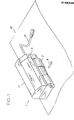
- FIG. 1 shows a schematic perspective view of a hand scanner according to an embodiment of the present invention.
- a scanning unit 1 is encased by a casing 11 and has a guide roller 2 for moving on a copy 10 in the direction indicated by an arrow 4 (subscanning direction), a speed regulator 3 for regulating the moving speed of the hand scanner, and a cable 28 for electrically connecting the hand scanner to an external device (not shown) such as a computer.
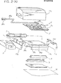
- Fig. 2 (A) shows an exploded perspective view of the hand scanner shown in Fig. 1.
- the casing 11 is composed of an aluminum base frame lla, side covers llb and an upper cover llc.
- a glass plate 9 is mounted on the bottom portion of the base frame lla so as to face the surface of a copy 10.
- a light emitting diode array (LED array) 7 for irradiating the surface of the copy 10 is mounted on the bottan surface of the base frame lla at a groove 29b.
- LED array light emitting diode array
- An optical lens system 8 such as a SELFOC lens array is fixed to a groove 29c at the bottom surface of the base frame lla so as to transfer the reflected light from the surface of the copy 10 to the upper side of the base frame lla through an opening 29d provided above the groove 29c on the upper surface of the base frame lla.
- an electrical circuit board 6 comprising a substrate 6c mounting thereon an electrical circuitry including a drive circuit and a read signal processing circuit, and a connector 6e.
- a cable 28a is connected at an end with a connector 28b which is connected with the connector 6e, and at the other end with a connector 28c which is connected with an external device (not shown).
- a photoelectric conversion device 5 such as a charge coupled device (CCD) image sensor for recieving the light transferred by the lens system 8 to obtain an image information corresponding to the image on the copy 10.
- CCD charge coupled device
- a guide roller 2 is loosely fitted into a groove 29a at the bottom surface of the base frame lla.
- the both ends of the shaft of the guide roller 2 are respectively fitted into holes lld provide on the side covers llb, one end of the shaft being connected to the speed regulator 3. This connection will be described later with reference to Fig. 3.
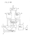
- Fig. 2 (B) shows a schematic block diagram of the hand scanner configured as shown in Fig. 2 (A).
- a drive circuit 6a is responsive to a drive information sent fran an external device through an input/output (I/O) interface circuit 30 and drive the-LED array 7, the photoelectric conversion device 5 and the speed regulator 3.
- the light irradiated by the LED array 7 passes through the glass plate 9, reflected by the surface of the copy 10, passes again through the glass plate 9, transferred by the lens system 8, and received by the photoelectric conversion device 5.
- the photoelectric conversion device 5 detects the image information contained in the reffected light and sends the detected image information to a signal processing circuit 6b.
- the signal processing circuit 6b processes the image information and sends the processed image information to the external device through the I/O interface circuit 30.
- the speed regulator 3 is connected with the guide roller 2 so as to regulate the moving speed of the hand scanner.
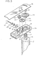
- Fig. 3 shows an exploded perspective view of an embodiment of the speed regulator 3, in which a speed regulating mechanism is provided in a casing composed of a base frame 3a and an upper cover 3b.
- a shaft 2a of the guide roller 2 is inserted into a coil spring 31 and connected to the shaft of a gear 12a which is located in the base frame 3a and exposed at its shaft from an opening 32 of the base frame 3a, the shaft of the gear 12a being mounted on a pole 33 fixed to the upper cover 3b.
- the gear 12a is engaged with a gear 12b which is coaxial with a gear 12c mounted on a pin 34 fixed to the base frame 3a.
- the gear 12c is engaged with a gear 12d which is coaxial with a gear 12e mounted on a pin 35 fixed to the base frame 3a.
- the gear 12e is engaged with a worm gear 13 which is supported at one end by a bearing 37 and at the other end by a frictional housing 15 which is fixed to a slot 36.
- a friction disc 14a such as a rubber disc fixed to a fixing plate 14b is mounted on the worm gear 13 so as to be rotatable with the worm gear 13.
- the inner surface of the frictional housing 15 contacts the friction disc 14a so that the rotation of the worm gear 13 is resisted by the friction force produced by the contact of the friction disc 14a with the inner surface of the frictional housing 15. Since the worm gear 13 is connected via the gears 12a-e to the guide roller 2, the rotation of the guide roller 2 is regulated by the abovesaid friction force.
- the friction disc 14a may be constructed to expand radially according to the rotational speed of the worm gear 13 so as to become contact with the inne surface of the frictional housing 15 when the rotational speed exceeds a predetermined speed, which produces a load proportional to the square of the angular velociy ( ⁇ ) of the guide roller 2. This allows the hand scanner to move approximately at a constant speed when moved by a hand.
- the range of variation of the thus regulated moving speed of the scanning unit 1 is as small as ⁇ 3% of the average speed or below, and hence the distortion of the read image relative to the original image is as small as ⁇ 3% or below, which practically is not any problem.
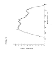
- Fig. 4 is a graph showing the variation of the moving speed of the scanning unit 1 of the hard scanner of Fig. 1, when the scanning unit 1 is moved without the speed regulator.
- the moving speed of the scanning unit varies over a wide range when the scanning unit 1 is moved without the speed regulator .
- the speed regulator reduces the range of variation of the moving speed effectively to an extremely small range.
- FIG. 6 A hand scanner equipped with a flywheel speed regulator embodying the present invention is shown in Fig. 6.
- Fig. 7 is a detail view of the flywheel speed regulator.
- a guide roller 16 rotates as a scanning unit 1 is moved in the subscanning direction indicated by an arrow 4.
- the rotation of the guide roller 16 is transmitted to a flywheel 17.
- the minute variation of the moving speed of the hand-operated scanning unit 1 is absorbed by the inertia of the flywheel 17.
- weights 19 are pressed against the inner surface of a pipe 21 by centrifugal force 20 so that a frictional resistance works on the weights 19.
- the magnitude of the frictional resistance can optionally be decided by selectively deciding the spring constant of a spring 22, the weight of the weights 19, the revolving rate of the rotary shaft 18 and the coefficient of friction between the weight 19 and the inner surface of the pipe 21.
- the frictional resistance is proportional to the revolving rate of the rotary shaft 18. This frictional resistance tends to maintain the revolving rate of the guide roller at a constant level. Consequently, the moving speed of the scanning unit 1 in the subscanning direction indicated by the arrow 4 is controlled for an approximate uniform motion.
- the minute variations of the moving speed of the scanning unit 1 attributable to the manual operation of the scanning unit 1 are absorbed by the inertia of the flywheel 17, and hence the scanning unit 1 moves smoothly.
- the resultant variation of the moving speed of the hand-operated scanning unit in the subscanning direction is as small as ⁇ 2% of the average speed or below, and hence the distortion of the read image relative to the original image is reduced satisfactorily to 2% or below.
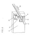
- Fig. 8 shows a third embodiment of the present invention.
- a scanning unit 27 (Figs. 1, 2 and 6) is moved along a guide rail 23 in the subscanning direction indicated by an arrow 28, a guide roller 22 rotates, and thereby a DC motor 24 is rotated in the reverse direction.
- the DC motor functions as a generator which produces a load practically proportional to the revolving rate thereof.
- the load thus produced tends to maintain the revolving rate of the guide roller at a fixed value, which controls the moving speed of the scanning unit for an approximate uniform motion.
- the guide roller 22 also rotates the rotary shaft of a rotary encoder 25.
- the rotary encoder 25 is adpated to provide pulse signals so that the ratio of the number of pulse signals to the scanning pitch of the scanning unit 27 in the subscanning direction indicated by the arrow 28 is an integral ratio.
- the rotary encoder provides ten pulse signals every 1/16mm movement of the scanning unit for scanning operation at a resolving power of 16 lines/mm. Accordingly, it is possible to recognize the position of the scanning unit 27 along the subscanning direction at a high accuracy of one-tenth of the subscanning pitch.
- the composite function of the rotary encoder and the speed regulator 24 (a device which produces a load by rotating the DC motor in the reverse direction) reduced the distortion of the read image relative to the original image on the document to 1% or below. Even in case the speed regulator 24 does not function satisfactorily due to the movement of the scanning unit 27 at a low moving speed, the distortion of the image attributable to the variation of the moving speed of the scanning unit can be corrected.
- the change of the resolving power of the CCD image sensor 5 can be achieved by setting the frequency dividing ratio between the reset pulse and the clock pulse of the driving circuit at a predetermined ratio. For example, if the ratio between the clock pulse and the reset pulse is set at 2:1, the resolving power of the CCD image sensor 5 is changed from 16 lines/mm to 8 lines/mm.
- a photocoupler attached to the scanning unit 27 for indicating a read starting point and a read terminal point. Furthermore., varying the luminous intensity of the light source 7 (Fig. 2) mounted on the scanning unit 27 according to the variation of the pulse signals of the rotray encoder 25 enables accurate reading of the original image.
Landscapes
- Engineering & Computer Science (AREA)
- Multimedia (AREA)
- Signal Processing (AREA)
- Power Engineering (AREA)
- Facsimile Scanning Arrangements (AREA)
- Image Input (AREA)
Applications Claiming Priority (2)
| Application Number | Priority Date | Filing Date | Title |
|---|---|---|---|
| JP14462984A JPS6124365A (ja) | 1984-07-12 | 1984-07-12 | ハンドスキヤナ− |
| JP144629/84 | 1984-07-12 |
Publications (2)
| Publication Number | Publication Date |
|---|---|
| EP0168256A2 true EP0168256A2 (fr) | 1986-01-15 |
| EP0168256A3 EP0168256A3 (fr) | 1988-03-02 |
Family
ID=15366485
Family Applications (1)
| Application Number | Title | Priority Date | Filing Date |
|---|---|---|---|
| EP85304969A Withdrawn EP0168256A3 (fr) | 1984-07-12 | 1985-07-11 | Dispositif manuel d'analyse |
Country Status (3)
| Country | Link |
|---|---|
| US (1) | US4703186A (fr) |
| EP (1) | EP0168256A3 (fr) |
| JP (1) | JPS6124365A (fr) |
Cited By (9)
| Publication number | Priority date | Publication date | Assignee | Title |
|---|---|---|---|---|
| EP0267456A3 (en) * | 1986-10-16 | 1989-05-24 | Sharp Kabushiki Kaisha | An image reader |
| EP0298482A3 (en) * | 1987-07-08 | 1990-10-24 | Sharp Kabushiki Kaisha | Image input device |
| GB2244188A (en) * | 1990-05-15 | 1991-11-20 | Copam Electronics Corp | Portable facsimile machine |
| EP0616461A3 (fr) * | 1993-03-15 | 1994-10-26 | Hewlett Packard Co | Balayeur optique à commande manuelle avec régulateur de vitesse. |
| US5723859A (en) * | 1996-01-29 | 1998-03-03 | Hewlett-Packard Company | Line contact hand-held scanning device and method having a light path substantially perpendicular to the orientation of the object at a line portion |
| US5777321A (en) * | 1996-01-29 | 1998-07-07 | Hewlett-Packard Company | Scanning device with non-contact optical components |
| US6064496A (en) * | 1997-06-18 | 2000-05-16 | Hewlett-Packard Company | Scanning device with floating window member |
| US6118553A (en) * | 1998-01-28 | 2000-09-12 | Hewlett-Packard Company | Compact motor drive and active speed governor with optical encoder for scanner mechanisms |
| US6639203B1 (en) | 1997-07-02 | 2003-10-28 | Hewlett-Packard Development Company, L.P. | Catadioptric lens system for a scanning device |
Families Citing this family (28)
| Publication number | Priority date | Publication date | Assignee | Title |
|---|---|---|---|---|
| JPS6071275A (ja) * | 1983-09-28 | 1985-04-23 | Toshiba Corp | 画像出力装置 |
| GB2183875B (en) * | 1985-12-05 | 1990-02-21 | Burroughs Corp | Card reading apparatus |
| US4793812A (en) * | 1987-10-05 | 1988-12-27 | Xerox Corporation | Hand held optical scanner for omni-font character recognition |
| US6109527A (en) * | 1989-07-07 | 2000-08-29 | Koizumi; Haruyuki | Handy image scanner |
| US5142131A (en) * | 1989-08-21 | 1992-08-25 | Ncr Corporation | Hand-held bar code reader |
| US5192856A (en) * | 1990-11-19 | 1993-03-09 | An Con Genetics, Inc. | Auto focusing bar code reader |
| US5182450A (en) * | 1991-11-06 | 1993-01-26 | Primax Electronics Ltd. | Handheld image scanner with automatic movement control |
| US5448050A (en) * | 1992-11-13 | 1995-09-05 | Psc Inc. | Integrated bar code reading and location mouse |
| US5381020A (en) * | 1993-03-31 | 1995-01-10 | Hewlett-Packard Company | Hand-held optical scanner with onboard battery recharging assembly |
| USD369353S (en) | 1994-02-11 | 1996-04-30 | Leica Lasertechnik Gmbh | Confocal laser scanner for use with a microscope |
| US5504367A (en) * | 1994-03-21 | 1996-04-02 | Intermec Corporation | Symbology reader illumination system |
| USD369148S (en) | 1995-05-05 | 1996-04-23 | Umax Data System Inc. | Roller type gray scale scanner |
| USD370008S (en) | 1995-06-08 | 1996-05-21 | Silitek Corporation | Scanner |
| IL114367A (en) * | 1995-06-27 | 1999-11-30 | Wizcom Technologies Ltd | Hand-holdable optical scanner particularly useful as electronic translator |
| US5744795A (en) * | 1995-07-31 | 1998-04-28 | Hewlett-Packard Company | Illumination strobing in a scanner to improve image sharpness and power consumption |
| US6010072A (en) * | 1996-05-20 | 2000-01-04 | Nec Corporation | Hand scanner movable over a document without meandering |
| US5923444A (en) * | 1997-04-14 | 1999-07-13 | Hewlett-Packard Company | Floating image head design for portable scanner |
| US5995243A (en) * | 1997-06-18 | 1999-11-30 | Hewlett-Packard Company | Illumination system with white level calibration for hand-held scanner |
| US6042013A (en) * | 1997-11-17 | 2000-03-28 | Xerox Corporation | Multi-colored illuminator apparatus for a scanner device |
| USD426240S (en) * | 1999-07-15 | 2000-06-06 | Matsushita Electric Industrial Co., Ltd. | Scanner |
| US7133068B2 (en) * | 2000-03-06 | 2006-11-07 | Sony Corporation | System and method for creating still images by utilizing a video camera device |
| JP2002247309A (ja) * | 2001-02-22 | 2002-08-30 | Fujitsu Ltd | イメージスキャナ |
| US6851608B1 (en) * | 2002-03-07 | 2005-02-08 | Commerciant, L.P. | System and method for uncontrolled velocity scanning |
| TWI244320B (en) * | 2004-10-20 | 2005-11-21 | Asia Optical Co Inc | Scanning unit having anti-reflective layers with high reflectivity |
| US7598683B1 (en) | 2007-07-31 | 2009-10-06 | Lsi Industries, Inc. | Control of light intensity using pulses of a fixed duration and frequency |
| US8903577B2 (en) | 2009-10-30 | 2014-12-02 | Lsi Industries, Inc. | Traction system for electrically powered vehicles |
| US8604709B2 (en) | 2007-07-31 | 2013-12-10 | Lsi Industries, Inc. | Methods and systems for controlling electrical power to DC loads |
| US8526067B2 (en) * | 2011-04-12 | 2013-09-03 | Sky Light Electronic (Shenzhen) Limited | Handheld portable scanner |
Family Cites Families (8)
| Publication number | Priority date | Publication date | Assignee | Title |
|---|---|---|---|---|
| FR876367A (fr) * | 1940-10-30 | 1942-11-04 | Bosch Gmbh Robert | Projecteur cinématographique, en particulier pour films étroits |
| US2571085A (en) * | 1948-07-28 | 1951-10-09 | Clifford Cecil Frank | Magnetic escapement counting and like mechanism |
| FR2115542A5 (fr) * | 1970-11-24 | 1972-07-07 | Fray Marcel | |
| US3918028A (en) * | 1973-01-05 | 1975-11-04 | Data Source Corp | Hand held optical reader |
| JPS59100128U (ja) * | 1982-12-23 | 1984-07-06 | 株式会社ニフコ | オイル式ダンパ− |
| AT382353B (de) * | 1983-04-13 | 1987-02-25 | Otis Elevator Co | Geschwindigkeitsbegrenzer fuer einen aufzug |
| US4553035A (en) * | 1983-08-30 | 1985-11-12 | Mylex Corporation | Data acquisition control method and system for a hand held reader |
| US4582188A (en) * | 1985-02-22 | 1986-04-15 | Variable Control Systems, Inc. | Speed controller for pallets |
-
1984
- 1984-07-12 JP JP14462984A patent/JPS6124365A/ja active Pending
-
1985
- 1985-07-11 EP EP85304969A patent/EP0168256A3/fr not_active Withdrawn
- 1985-07-11 US US06/753,966 patent/US4703186A/en not_active Expired - Lifetime
Cited By (10)
| Publication number | Priority date | Publication date | Assignee | Title |
|---|---|---|---|---|
| EP0267456A3 (en) * | 1986-10-16 | 1989-05-24 | Sharp Kabushiki Kaisha | An image reader |
| US4901163A (en) * | 1986-10-16 | 1990-02-13 | Sharp Kabushiki Kaisha | Image reader for a portable copier |
| EP0298482A3 (en) * | 1987-07-08 | 1990-10-24 | Sharp Kabushiki Kaisha | Image input device |
| GB2244188A (en) * | 1990-05-15 | 1991-11-20 | Copam Electronics Corp | Portable facsimile machine |
| EP0616461A3 (fr) * | 1993-03-15 | 1994-10-26 | Hewlett Packard Co | Balayeur optique à commande manuelle avec régulateur de vitesse. |
| US5723859A (en) * | 1996-01-29 | 1998-03-03 | Hewlett-Packard Company | Line contact hand-held scanning device and method having a light path substantially perpendicular to the orientation of the object at a line portion |
| US5777321A (en) * | 1996-01-29 | 1998-07-07 | Hewlett-Packard Company | Scanning device with non-contact optical components |
| US6064496A (en) * | 1997-06-18 | 2000-05-16 | Hewlett-Packard Company | Scanning device with floating window member |
| US6639203B1 (en) | 1997-07-02 | 2003-10-28 | Hewlett-Packard Development Company, L.P. | Catadioptric lens system for a scanning device |
| US6118553A (en) * | 1998-01-28 | 2000-09-12 | Hewlett-Packard Company | Compact motor drive and active speed governor with optical encoder for scanner mechanisms |
Also Published As
| Publication number | Publication date |
|---|---|
| JPS6124365A (ja) | 1986-02-03 |
| EP0168256A3 (fr) | 1988-03-02 |
| US4703186A (en) | 1987-10-27 |
Similar Documents
| Publication | Publication Date | Title |
|---|---|---|
| EP0168256A2 (fr) | Dispositif manuel d'analyse | |
| US4319283A (en) | Portable copying machine | |
| EP0399651B1 (fr) | Dispositif et procédé pour le balayage d'images | |
| US4707747A (en) | Hand held scanning input device and system | |
| US4075478A (en) | Floating head encoder | |
| JPS63154091A (ja) | ブラシレス直流電動機の回転数検出装置 | |
| US4476457A (en) | Rotary encoder | |
| EP0119488B1 (fr) | Appareil de détection de position | |
| US5266787A (en) | Laser scanner using two scan motors independently controlled by a single signal | |
| US6330082B1 (en) | Converter for optical scanner | |
| EP0388139B1 (fr) | Régulateur de vitesse et instrument incorporant ce régulateur | |
| US5576536A (en) | Image forming apparatus including motor-driven rotary scanner and system for judging if motor rotation comes to steady state and for maintaining rotation at steady state | |
| DE58900277D1 (de) | Abgeschirmte winkelmesseinrichtung in direktem anbau an einer antriebseinheit. | |
| JPS62143557A (ja) | 画像読み取り装置 | |
| US3831076A (en) | Sector scanning control system | |
| US5488225A (en) | Rotary scanner and light beam scanning system having a specified relationship between the facets of the scanning mirror and the commuter segments of the motor | |
| CN116760931B (zh) | 一种提高线扫相机拍摄精度的方法与装置 | |
| JP4323298B2 (ja) | 地すべり記録器 | |
| JPH08115012A (ja) | 感光体の回転情報検出器を備えた画像形成装置及び検知方法 | |
| JP2501936Y2 (ja) | 画像情報入力装置 | |
| JPS6111806Y2 (fr) | ||
| JPS61160767A (ja) | 複写装置 | |
| JPS57166674A (en) | Rereading system for optical character reader | |
| GB1088288A (en) | Improvements relating to facsimile systems | |
| JPH04372563A (ja) | リニア直流モータ及びこのモータを用いたイメージスキャナ |
Legal Events
| Date | Code | Title | Description |
|---|---|---|---|
| PUAI | Public reference made under article 153(3) epc to a published international application that has entered the european phase |
Free format text: ORIGINAL CODE: 0009012 |
|
| AK | Designated contracting states |
Designated state(s): DE FR GB IT |
|
| PUAL | Search report despatched |
Free format text: ORIGINAL CODE: 0009013 |
|
| AK | Designated contracting states |
Kind code of ref document: A3 Designated state(s): DE FR GB IT |
|
| 17P | Request for examination filed |
Effective date: 19880901 |
|
| 17Q | First examination report despatched |
Effective date: 19900522 |
|
| STAA | Information on the status of an ep patent application or granted ep patent |
Free format text: STATUS: THE APPLICATION IS DEEMED TO BE WITHDRAWN |
|
| 18D | Application deemed to be withdrawn |
Effective date: 19901003 |
|
| RIN1 | Information on inventor provided before grant (corrected) |
Inventor name: UEDA, KAZUYA Inventor name: SAITO, FUMINARI Inventor name: NAKAYAMA, NOBUO Inventor name: NAGAMINE, KENI |