EP0168261A2 - Verbinder für Hochleistungsstrahl - Google Patents
Verbinder für Hochleistungsstrahl Download PDFInfo
- Publication number
- EP0168261A2 EP0168261A2 EP85305001A EP85305001A EP0168261A2 EP 0168261 A2 EP0168261 A2 EP 0168261A2 EP 85305001 A EP85305001 A EP 85305001A EP 85305001 A EP85305001 A EP 85305001A EP 0168261 A2 EP0168261 A2 EP 0168261A2
- Authority
- EP
- European Patent Office
- Prior art keywords
- optical fiber
- connector
- high energy
- energy beam
- set forth
- Prior art date
- Legal status (The legal status is an assumption and is not a legal conclusion. Google has not performed a legal analysis and makes no representation as to the accuracy of the status listed.)
- Granted
Links
- 239000013307 optical fiber Substances 0.000 claims abstract description 128
- 239000000126 substance Substances 0.000 claims abstract description 55
- PNEYBMLMFCGWSK-UHFFFAOYSA-N Alumina Chemical compound [O-2].[O-2].[O-2].[Al+3].[Al+3] PNEYBMLMFCGWSK-UHFFFAOYSA-N 0.000 claims abstract description 19
- 230000008018 melting Effects 0.000 claims abstract description 15
- 238000002844 melting Methods 0.000 claims abstract description 15
- VYPSYNLAJGMNEJ-UHFFFAOYSA-N Silicium dioxide Chemical compound O=[Si]=O VYPSYNLAJGMNEJ-UHFFFAOYSA-N 0.000 claims description 25
- 229910052593 corundum Inorganic materials 0.000 claims description 16
- 229910001845 yogo sapphire Inorganic materials 0.000 claims description 16
- 230000005540 biological transmission Effects 0.000 claims description 5
- -1 LiO2 Chemical compound 0.000 claims description 3
- 230000002093 peripheral effect Effects 0.000 claims description 3
- 230000004323 axial length Effects 0.000 claims description 2
- TWNQGVIAIRXVLR-UHFFFAOYSA-N oxo(oxoalumanyloxy)alumane Chemical compound O=[Al]O[Al]=O TWNQGVIAIRXVLR-UHFFFAOYSA-N 0.000 claims description 2
- MCMNRKCIXSYSNV-UHFFFAOYSA-N ZrO2 Inorganic materials O=[Zr]=O MCMNRKCIXSYSNV-UHFFFAOYSA-N 0.000 claims 14
- 229910052681 coesite Inorganic materials 0.000 claims 11
- 229910052906 cristobalite Inorganic materials 0.000 claims 11
- 229910052682 stishovite Inorganic materials 0.000 claims 11
- 229910052905 tridymite Inorganic materials 0.000 claims 11
- GWEVSGVZZGPLCZ-UHFFFAOYSA-N Titan oxide Chemical compound O=[Ti]=O GWEVSGVZZGPLCZ-UHFFFAOYSA-N 0.000 claims 10
- 239000000377 silicon dioxide Substances 0.000 claims 10
- ODINCKMPIJJUCX-UHFFFAOYSA-N calcium oxide Inorganic materials [Ca]=O ODINCKMPIJJUCX-UHFFFAOYSA-N 0.000 claims 7
- QDOXWKRWXJOMAK-UHFFFAOYSA-N chromium(III) oxide Inorganic materials O=[Cr]O[Cr]=O QDOXWKRWXJOMAK-UHFFFAOYSA-N 0.000 claims 3
- ATJFFYVFTNAWJD-UHFFFAOYSA-N Tin Chemical compound [Sn] ATJFFYVFTNAWJD-UHFFFAOYSA-N 0.000 claims 2
- CJNBYAVZURUTKZ-UHFFFAOYSA-N hafnium(IV) oxide Inorganic materials O=[Hf]=O CJNBYAVZURUTKZ-UHFFFAOYSA-N 0.000 claims 2
- XOLBLPGZBRYERU-UHFFFAOYSA-N tin dioxide Chemical compound O=[Sn]=O XOLBLPGZBRYERU-UHFFFAOYSA-N 0.000 claims 2
- FUJCRWPEOMXPAD-UHFFFAOYSA-N Li2O Inorganic materials [Li+].[Li+].[O-2] FUJCRWPEOMXPAD-UHFFFAOYSA-N 0.000 claims 1
- ATUUNJCZCOMUKD-OKILXGFUSA-N MLI-2 Chemical compound C1[C@@H](C)O[C@@H](C)CN1C1=CC(C=2C3=CC(OC4(C)CC4)=CC=C3NN=2)=NC=N1 ATUUNJCZCOMUKD-OKILXGFUSA-N 0.000 claims 1
- KKCBUQHMOMHUOY-UHFFFAOYSA-N Na2O Inorganic materials [O-2].[Na+].[Na+] KKCBUQHMOMHUOY-UHFFFAOYSA-N 0.000 claims 1
- BPQQTUXANYXVAA-UHFFFAOYSA-N Orthosilicate Chemical group [O-][Si]([O-])([O-])[O-] BPQQTUXANYXVAA-UHFFFAOYSA-N 0.000 claims 1
- 229910019142 PO4 Inorganic materials 0.000 claims 1
- 229910004369 ThO2 Inorganic materials 0.000 claims 1
- RTAQQCXQSZGOHL-UHFFFAOYSA-N Titanium Chemical compound [Ti] RTAQQCXQSZGOHL-UHFFFAOYSA-N 0.000 claims 1
- GNTDGMZSJNCJKK-UHFFFAOYSA-N Vanadium(V) oxide Inorganic materials O=[V](=O)O[V](=O)=O GNTDGMZSJNCJKK-UHFFFAOYSA-N 0.000 claims 1
- 150000004645 aluminates Chemical group 0.000 claims 1
- 229910000147 aluminium phosphate Inorganic materials 0.000 claims 1
- 239000010432 diamond Substances 0.000 claims 1
- 229910003460 diamond Inorganic materials 0.000 claims 1
- XUCJHNOBJLKZNU-UHFFFAOYSA-M dilithium;hydroxide Chemical compound [Li+].[Li+].[OH-] XUCJHNOBJLKZNU-UHFFFAOYSA-M 0.000 claims 1
- QZQVBEXLDFYHSR-UHFFFAOYSA-N gallium(III) oxide Inorganic materials O=[Ga]O[Ga]=O QZQVBEXLDFYHSR-UHFFFAOYSA-N 0.000 claims 1
- JEIPFZHSYJVQDO-UHFFFAOYSA-N iron(III) oxide Inorganic materials O=[Fe]O[Fe]=O JEIPFZHSYJVQDO-UHFFFAOYSA-N 0.000 claims 1
- MRELNEQAGSRDBK-UHFFFAOYSA-N lanthanum oxide Inorganic materials [O-2].[O-2].[O-2].[La+3].[La+3] MRELNEQAGSRDBK-UHFFFAOYSA-N 0.000 claims 1
- CPLXHLVBOLITMK-UHFFFAOYSA-N magnesium oxide Inorganic materials [Mg]=O CPLXHLVBOLITMK-UHFFFAOYSA-N 0.000 claims 1
- 150000004767 nitrides Chemical group 0.000 claims 1
- KTUFCUMIWABKDW-UHFFFAOYSA-N oxo(oxolanthaniooxy)lanthanum Chemical compound O=[La]O[La]=O KTUFCUMIWABKDW-UHFFFAOYSA-N 0.000 claims 1
- 239000010452 phosphate Substances 0.000 claims 1
- 125000002467 phosphate group Chemical group [H]OP(=O)(O[H])O[*] 0.000 claims 1
- 229910052596 spinel Inorganic materials 0.000 claims 1
- 239000011029 spinel Substances 0.000 claims 1
- VEALVRVVWBQVSL-UHFFFAOYSA-N strontium titanate Chemical compound [Sr+2].[O-][Ti]([O-])=O VEALVRVVWBQVSL-UHFFFAOYSA-N 0.000 claims 1
- PBCFLUZVCVVTBY-UHFFFAOYSA-N tantalum pentoxide Inorganic materials O=[Ta](=O)O[Ta](=O)=O PBCFLUZVCVVTBY-UHFFFAOYSA-N 0.000 claims 1
- ZCUFMDLYAMJYST-UHFFFAOYSA-N thorium dioxide Chemical compound O=[Th]=O ZCUFMDLYAMJYST-UHFFFAOYSA-N 0.000 claims 1
- QORWJWZARLRLPR-UHFFFAOYSA-H tricalcium bis(phosphate) Chemical compound [Ca+2].[Ca+2].[Ca+2].[O-]P([O-])([O-])=O.[O-]P([O-])([O-])=O QORWJWZARLRLPR-UHFFFAOYSA-H 0.000 claims 1
- 229910000391 tricalcium phosphate Inorganic materials 0.000 claims 1
- FCTBKIHDJGHPPO-UHFFFAOYSA-N uranium dioxide Inorganic materials O=[U]=O FCTBKIHDJGHPPO-UHFFFAOYSA-N 0.000 claims 1
- 125000005289 uranyl group Chemical group 0.000 claims 1
- 239000000919 ceramic Substances 0.000 abstract description 8
- 229910052594 sapphire Inorganic materials 0.000 abstract description 8
- 239000010980 sapphire Substances 0.000 abstract description 8
- 238000009792 diffusion process Methods 0.000 abstract description 2
- 239000007769 metal material Substances 0.000 abstract description 2
- 229920000271 Kevlar® Polymers 0.000 description 10
- 239000004761 kevlar Substances 0.000 description 10
- RYGMFSIKBFXOCR-UHFFFAOYSA-N Copper Chemical compound [Cu] RYGMFSIKBFXOCR-UHFFFAOYSA-N 0.000 description 7
- 229910052802 copper Inorganic materials 0.000 description 7
- 239000010949 copper Substances 0.000 description 7
- 239000011230 binding agent Substances 0.000 description 6
- 230000003287 optical effect Effects 0.000 description 5
- 239000010453 quartz Substances 0.000 description 5
- 239000003822 epoxy resin Substances 0.000 description 4
- 229920000647 polyepoxide Polymers 0.000 description 4
- 229910001369 Brass Inorganic materials 0.000 description 3
- 239000010951 brass Substances 0.000 description 3
- 238000010276 construction Methods 0.000 description 3
- 230000000694 effects Effects 0.000 description 3
- 239000000463 material Substances 0.000 description 3
- 229910001220 stainless steel Inorganic materials 0.000 description 3
- 239000010935 stainless steel Substances 0.000 description 3
- 239000004677 Nylon Substances 0.000 description 2
- 230000004927 fusion Effects 0.000 description 2
- 238000010438 heat treatment Methods 0.000 description 2
- 238000004519 manufacturing process Methods 0.000 description 2
- 229920001778 nylon Polymers 0.000 description 2
- 229920000915 polyvinyl chloride Polymers 0.000 description 2
- 239000004800 polyvinyl chloride Substances 0.000 description 2
- 239000004593 Epoxy Substances 0.000 description 1
- 229910021607 Silver chloride Inorganic materials 0.000 description 1
- 230000002238 attenuated effect Effects 0.000 description 1
- 230000006866 deterioration Effects 0.000 description 1
- 239000011521 glass Substances 0.000 description 1
- 229910052751 metal Inorganic materials 0.000 description 1
- 239000002184 metal Substances 0.000 description 1
- QGLKJKCYBOYXKC-UHFFFAOYSA-N nonaoxidotritungsten Chemical compound O=[W]1(=O)O[W](=O)(=O)O[W](=O)(=O)O1 QGLKJKCYBOYXKC-UHFFFAOYSA-N 0.000 description 1
- 239000011368 organic material Substances 0.000 description 1
- 230000000644 propagated effect Effects 0.000 description 1
- HKZLPVFGJNLROG-UHFFFAOYSA-M silver monochloride Chemical compound [Cl-].[Ag+] HKZLPVFGJNLROG-UHFFFAOYSA-M 0.000 description 1
- 238000005476 soldering Methods 0.000 description 1
- 229910001930 tungsten oxide Inorganic materials 0.000 description 1
- 238000003466 welding Methods 0.000 description 1
Images



Classifications
-
- G—PHYSICS
- G02—OPTICS
- G02B—OPTICAL ELEMENTS, SYSTEMS OR APPARATUS
- G02B6/00—Light guides; Structural details of arrangements comprising light guides and other optical elements, e.g. couplings
- G02B6/24—Coupling light guides
- G02B6/36—Mechanical coupling means
- G02B6/38—Mechanical coupling means having fibre to fibre mating means
- G02B6/3807—Dismountable connectors, i.e. comprising plugs
- G02B6/381—Dismountable connectors, i.e. comprising plugs of the ferrule type, e.g. fibre ends embedded in ferrules, connecting a pair of fibres
- G02B6/3813—Dismountable connectors, i.e. comprising plugs of the ferrule type, e.g. fibre ends embedded in ferrules, connecting a pair of fibres for transmission of high energy beam
-
- G—PHYSICS
- G02—OPTICS
- G02B—OPTICAL ELEMENTS, SYSTEMS OR APPARATUS
- G02B6/00—Light guides; Structural details of arrangements comprising light guides and other optical elements, e.g. couplings
- G02B6/24—Coupling light guides
- G02B6/26—Optical coupling means
- G02B6/32—Optical coupling means having lens focusing means positioned between opposed fibre ends
-
- G—PHYSICS
- G02—OPTICS
- G02B—OPTICAL ELEMENTS, SYSTEMS OR APPARATUS
- G02B6/00—Light guides; Structural details of arrangements comprising light guides and other optical elements, e.g. couplings
- G02B6/24—Coupling light guides
- G02B6/36—Mechanical coupling means
- G02B6/38—Mechanical coupling means having fibre to fibre mating means
- G02B6/3807—Dismountable connectors, i.e. comprising plugs
- G02B6/389—Dismountable connectors, i.e. comprising plugs characterised by the method of fastening connecting plugs and sockets, e.g. screw- or nut-lock, snap-in, bayonet type
- G02B6/3894—Screw-lock type
Definitions
- This invention relates to a connector mounted on an end of optical fiber for transmitting the high energy beam, such as the laser beam, used for industries such as welding and soldering and for medical treatment such as cutting out the affected parts.
- the connector plugs are mounted on the incident and outgoing ends of the optical fiber used for transmitting this kind of high energy laser beam so that the plugs are adapted to connect with receptacles one of which is at the incident end and contains a lens attached to a laser system and other of which at the outgoing end contains a lens opposite to an object to be processed.
- Such plug of the conventional connector for the high energy beam is constructed as follows: Fig. 1 is a sectional view exemplary of a plug at the incident end side of the conventional connector for the high energy beam and Fig. 2 is a front view exemplary of the plug when viewed on the line II - II in the direction of the arrow in Fig. 1,. in which reference numeral 1 designates a cord containing therein a single optical fiber la, 2 designates a plug, and 3 lesignates a receptacle containing therein a lens 3a.
- the cord 1 is cut out at a sheath lb of polyvinylchloride (P.V.C.), a Kevlar (trade mark of Dupont) lc, and a jacket ld of nylon to expose the Kevlar lc, jacket ld and an optical fiber la in a desired length, so that a plug body 21 is sleeved across an axially intermediate portion of the bared optical fiber la and the root portion of the bared jacket ld.
- P.V.C. polyvinylchloride
- Kevlar trade mark of Dupont
- the plug body 21 is made from stainless steel, formed in a cylindrical shape, provided at the outer periphery of an axially intermediate portion with a flange 21a, sleeved across the bared optical fiber la and jacket ld, and fixed concentrically and integrally to the optical fiber la and jacket ld through epoxy resin 21b filled between the inner periphery of body 21 and the outer periphery of optical fiber la.
- the bared Kevlar lc covers the outer periphery of the root portion of plug body 21, and a skirt member 22 of stainless steel is sleeved on the sheath lb and the root portion of plug body 21 so that the Kevlar lc is sandwiched between the skirt member 22 and the outer periphery of the plug body 21 and fixed integrally thereto through a binder.
- reference numeral 23 designates a cap nut, which is screwably tightened to the outer periphery of the receptacle 3 in condition of inserting therein the utmost end portion of plug body 21, thereby insertably holding the plug body 21 to the receptacle 3.
- Such conventional optical fiber connector exposes at the utmost end face of the plug 2 the epoxy resin 21b which concentrically integrally fixes the optical fiber la and plug body 21.
- the laser system, lens 3a and optical fiber la are insufficient in alignment, the laser beam shifts from the incident end face at the optical fiber la so as to be projected on the epoxy resin 21b, whereby there is a fear that the epoxy resin 21b burns to cause an escape or damage of the plug.
- an optical connector for the high energy beam has already been disclosed in the Japanese Utility Model Application No. 59-20146 (1984) by the inventors of the present invention, the optical connector being so constructed that the plug body 21 is divided into a holder and a sleeve and combustibles are eliminated from the vicinity of the laser beam incident end face of the sleeve supporting the fore end of optical fiber, so that even when the incident laser beam shifts, the plug can be prevented from being damaged.
- Fig. 3 is a partially cutaway side view of the connector disclosed in the above application and Fig. 4 is a schematic front view of the connector when viewed on the line IV - IV in the direction of the arrow in Fig. 3, in which reference numeral 31 designates a skirt member, 32 designates a holder, 33 designates a sleeve, and 34 designates a cap nut.
- the sleeve 33 is cylindrical and made from copper, has at an axially intermediate portion an optical fiber support portion 33a of an inner diameter about equal to a diameter of the optical fiber la, has both axial end portions somewhat larger in an inner diameter than the optical fiber support portion 33a, and screws at a screw thread 33b formed at the inner periphery of the root portion with an utmost end of the holder 32 so that the sleeve 33 is connected thereto.
- the optical fiber la is held by the skirt member 31, holder 32, and optical fiber support portion 33a at the intermediate portion of sleeve 33, and level at the utmost end face with the front end face of sleeve 33.
- annular gap 33c having a desired axial length from the end of optical fiber la is formed between the sleeve 33 and the optical fiber la. Accordingly, even when the laser beam is incident shifting from the end face of optical fiber la, since there are no combustibles around the optical fiber la, the inconvenience of burning the connector can be prevented.
- the optical connector constructed as foregoing allows the laser beam shifting from the end face of optical fiber la to be incident through the aforesaid gap 33c on the outer periphery of optical fiber la or the inner periphery of the larger diameter portion at the fore end of sleeve 33.
- the laser beam is incident on the outer periphery of optical fiber la, some fusion is created on the same, but leads to less breakage.
- copper of material for the sleeve 33 is molten and scattered to strike the outer periphery of optical fiber la, thereby creating the problem in that the optical fiber la may be cracked on the outer periphery so as to be breakable.
- reference numeral 1 designates a cord containing therein a single core optical fiber la
- 2 designates a plug
- 5 designates a receptacle.
- the cord 1 is cut out at a sheath lb of polyvinylchloride (P.V.C.), a Kevlar lc and a jacket ld of nylon, so that the jacket ld, Kevlar lc and optical fiber la are bared each in a desired length.
- P.V.C. polyvinylchloride
- Kevlar lc a Kevlar lc and a jacket ld of nylon
- a holder 41 is fixedly sleeved across an axially intermediate portion of the bared portion of optical fiber la and the root portion of the bared portion of jacket ld
- a skirt member 42 is fixed across the root portion of the holder 41 and the outer periphery of the utmost end of sheath lb
- a sleeve 43 is fixed across the utmost end of the bared portion of optical fiber la and the utmost end of holder 41
- a cap nut 44 is axially movably sleeved across the holder 41, skirt member 42 and sleeve 43.
- the holder 41 is made from brass, formed in a cylinder whose inner diameter is slightly larger than a diameter of jacket ld, reduced in an outer diameter at the root portion to form a shoulder 41b, provided at the outer periphery near the utmost end with a larger diameter flange 41a and at the outer periphery ahead of the flange 41a with a screw thread 41c. Also, the holder 41 is sleeved across near the root portion of the bared portion of jacket ld and an intermediate portion of the bared portion of optical fiber la and covered at the outer periphery of the smaller outer diameter portion of the root portion with the bared Kevlar lc.
- a metallic sleeve 41d in relation of abutting at the root portion against the utmost end of jacket ld and of somewhat projecting at the utmost end from the fore end of holder 41.
- Epoxy series binders 41e and 41f are filled between the metallic sleeve 41d and the inner periphery of holder 41, and the metallic sleeve 41d and the outer periphery of optical fiber la, the holder 41 being concentrically and integrally bonded with the optical fiber la through the binders 41e and 41f and metallic sleeve 41d.
- the skirt member 42 is made from brass as the same as the holder 41, formed in a cylindrical shape of an inner diameter of the portion other than the fore end, slightly larger than an outer diameter of the reduced diameter portion at the root portion of holder 41, and sleeved across the outer periphery of the fore end of sheath lb and that of the root portion of holder 41 covered by the Kevlar lc.
- the outer periphery of the root portion of holder 41 covered by the Kevlar lc, the inner periphery thereof, and the inner periphery of the fore end of skirt member 42, are coated with a binder, so that the fore end portion of skirt member 42 and the root portion of holder 41 sandwich therebetween the Kevlar lc, the three members being fixed integrally with each other by the binder.
- the sleeve 43 is cylindrical, has at an axially intermediate portion an optical fiber support portion 43f of an inner diameter equal to or slightly larger than a diameter of optical fiber la, formed at both axial sides of the support portion 43f to be somewhat larger in an inner diameter than the optical fiber support portion 43f so as to form gaps 43c and 43d between the inner peripheries of sleeve 43 and the outer periphery of optical fiber la, and provided at the inner periphery of the root portion with a screw thread 43a.
- the screw thread 43a is coated with a binder and screws with the screw thread 41c at the fore end of holder 41, thereby connecting the sleeve 43 concentrically and integrally with the fore end of holder 41 in condition of being sleeved on the optical fiber la.
- the sleeve 43 is formed at the optical fiber support portion 43f only of high heat resistant inorganic substance and press-fitted into the depth of gap 43c and other portions are made from copper as the same as the conventional connector shown in Fig. 3.
- reference numeral 43g designates a positioning stopper for optical fiber support portion 43f when fitted into the sleeve 43.
- the optical fiber support portion 43f at the sleeve 43 employs a transparent or a translucent heat resistant inorganic substance of the melting point at a temperature of 1500°C or more and of the refractive index higher than that of clad of optical fiber la, for example, 1450°C, as shown in Table 1, or an opaque or translucent and amorphous heat resistant inorganic substance of the melting point at a temperature of 1500°C or more, the so-called the fine ceramics, as shown in Table 2.
- a typical transparent or translucent substance shown in Table 1 cites sapphire.
- the sapphire when in use, is of the melting point at 2030 C and of refractive index of 1.76 regardless of being natural or synthetic and satisfies the above requirement.
- the connector using sapphire of the invention was mounted on quartz series optical fiber of a core diameter of 400 ⁇ m and a clad diameter of 500 ⁇ m and applied with pulse of 20J, 8 m sec and 5 pps for one minute in condition of delaying an incident axis by 30' (minutes), but any trouble was not found.
- the opaque or translucent amorphous substances shown in Table 2 are in a group of substances, so-called the fine ceramics, in which Al203 (aluminum oxide) is typical.
- the amorphous substance A1 2 0 3 is of the melting point of 2050°C.
- the connectors of the invention using the fine ceramics of material Al 2 O 3 were mounted on both ends of a pure quartz . optical fiber of core diameter of 400 ⁇ m and clad diameter of 500 ⁇ m, and the laser beam of 100 watt and CWYAG was incident on the connectors for one minute in condition of shifting by angle of 6°, but there was not found any trouble. However, in the same condition as the above, when the connectors of, for example, fine ceramics of tungsten oxide of the melting point of 1470°C, was used, the ceramic portion has vaporized.
- the transparent or translucent substances shown in Table 1 need only transmit 5 % or more of the quantity of the incident light in a transmission distance of 1 mm.
- the opaque or translucent substances in Table 2 transmit only less than 5 % of the quantity of the incident light in the transmission distance of 1 mm.
- the substances shown in Tables 1 and 2 are preferable to have a coefficient of thermal expansion as near that of glass as possible.
- the reason for this is that the optical fiber support portion 43f thermally expands to press hard the optical fiber la and give it stress, whereby the microbending loss (deterioration in the light transmission efficiency by the stress applied to the optical fiber) is created, and when the microbends further are repeated, the optical fiber may be damaged.
- the optical fiber la is 150 to 1250 m in diameter, projects from the utmost end of metallic sleeve 41d into the sleeve 43, passes through a bore 43b provided at inside of the optical fiber support portion 43f of the sleeve 43 and having a diameter about equal to that of the optical fiber, and positioned at the end at the incident side concentrically with the sleeve 43 and to be level with the utmost end face thereof.
- the gaps 43c and 43d formed between the root portion of sleeve 43 and the inner periphery thereof and the outer periphery of optical fiber la contain air only and any combustible, for example, an organic material does not at all exist in the gaps 43c and 43d.
- the reason for keeping the end face of optical fiber la level with the utmost end face of sleeve 43 is that when the optical fiber la projects at its end face from the utmost end face of sleeve 43, there is a fear of breaking the optical fiber la, and when the end face thereof is recessed, it is difficult to clean the same. Hence, the end face of optical fiber la need not be level with the utmost end face of sleeve 43.
- the cap nut 44 is made of stainless steel or brass and provided at the inner periphery of the fore end portion with a screw thread 44a tightly screwable with a screw thread 5b formed at the outer periphery of receptacle 5 at the laser beam outgoing side and. at the inner periphery near the rear end with an inner flange 44b of an inner diameter smaller than a diameter of the flange 41a at the holder 41.
- a coil spring 45 is interposed between the inner flange 44b and the flange 41a at the holder 41 and biases the cap nut 44 to move away from the receptacle 5.
- the receptacle 5 is made cylindrical as the same as the conventional one shown in Figs. 1 and 3 and contains a lens 5a fixed to face the laser beam outlet at a laser system (not shown).
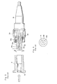
- the laser beam output from the laser system (not shown) is incident on the lens 5a as shown by the unshaded arrow in Fig. 5 so as to be converged and thereafter is incident on the end face of optical fiber la to thereby be propagated therein.
- the gap 43c therearound contains air only, whereby the air of course does not burn.
- the inner periphery is high in heat resistance not to be molten or vaporized.
- the laser beam . incident on the optical fiber support portion 43f transmits the optical fiber support portion 43f while being attenuated, reflectp by the stopper 43g made by metal and then just a little laser beam travels toward the rear gap 43d, thereby not heating the optical fiber la up to a high temperature at the rear gap 43d side.
- the laser beam incident on the optical fiber support portion 43f is hard to enter the optical fiber la because sapphire constituting the optical fiber support portion 43f has the refractive index higher than that of the clad of optical fiber la.
- the laser beam incident on the clad at the utmost end are examples of the laser beam incident on the clad at the utmost end.
- optical fiber support portion 43f higher in refractive index than the clad so that no laser beam transmits the clad of optical fiber la to the rear gap 43d, thereby restricting a temperature rise thereof.
- the connector for high energy beam of the invention constructed as shown in Fig. 5 and using sapphire of refractive index of 1.76, has been mounted on the incident end of a step index type quartz series optical fiber of a core diameter of 400 ⁇ m and a clad diameter of 500 ⁇ m and radiated by several tens of thousand pulses the YAG laser beam of pulse width of 8 m sec and output of 20J.
- a breakage fault in the optical fiber and also even when the incident axis shifts at an angle of 14 to 15 0 , the connector of the invention has not been broken.
- the conventional connector shown in Fig. 1 has at once been unusable, and that shown in Fig. 3, only when shifted by at an angle of 20 to 30', leads to a breakage of optical fiber.
- Figs. 7 and 8 are sectional side views of sleeves 43 in second and third embodiments of the invention.
- the optical fiber support portion 43f of the sleeve 43 and the inner peripheral portion thereof facing the gap 43c at the fore end side of optical fiber la are formed of a heat resistant inorganic substance as shown in Tables 1 and 2, other portions of sleeve 43 being made from copper as the same as the first embodiment.
- the above portion of heat resistant inorganic substance is press-fitted into the copper-made portion and positioned by a stopper 43g provided at the sleeve 43 as the same as the first embodiment.
- the optical fiber support portion 43f only is formed of transparent or translucent heat resistant inorganic substance, for example, sapphire, and subjected to the roughened surface processing at the outer periphery and end surface in contact with the inner periphery of the copper portion of sleeve 43 and with the stopper 43g, thereby forming the diffusing surfaces respectively.
- transparent or translucent heat resistant inorganic substance for example, sapphire
- the laser beam intended to transmit the optical fiber support portion 43 toward the holder 41, or transmit other copper-made portions is irregularly reflected or diffused by the diffusion surfaces 43h to expect energy attenuation, whereby there is no fear of heating the optical fiber la and stopper 43g and so on at a high temperatureo
- Fig. 9 is a sectional side view of a sleeve 43 in a fourth embodiment of the invention, in which whole of the sleeve 43 is formed of the high heat-resistant inorganic substances shown in Tables 1 and 2 and other portions are the same in construction as the sleeve 43 in the first embodiment (refer to Fig. 5).
- the sleeve 43 in this embodiment can be molded integrally by use of the opaque substance, especially Al 2 0 3 1 SiC, 3Al 2 O 3 ⁇ 2SiO, of the so-called fine ceramics, thereby enabling mass production in a low manufacturing cost.
- the opaque substance especially Al 2 0 3 1 SiC, 3Al 2 O 3 ⁇ 2SiO, of the so-called fine ceramics, thereby enabling mass production in a low manufacturing cost.
- Fig. 10 is a sectional side view of a sleeve 43 in a fifth embodiment of the invention, which as a whole is formed integrally of the high heat-resistant inorganic substance shown in-Tables 1 and 2 as the same as the fourth embodiment, but differs therefrom in that the fore end of the optical fiber support portion 43f, i.e., the end face 43e at the laser beam incident side, of the sleeve 43 is tapered at an angle ⁇ like a trancated cone whose diameter at the end side face of the optical fiber la is smallest, the angle 6 of inclination being desirable to be set to satisfy the following equation: ⁇ ⁇ 90° - arc tan (a/b),
- an incident angle a of the laser beam being out of the utmost end of optical fiber la is 90 0 or more even when the smallest, with respect to end face 43e.
- the laser beam incident on the end face 43e of the optical fiber support portion 43f is reflected toward the inner periphery of sleeve 43 facing the gap 43c, thereby avoiding inconvenience of fusing the optical fiber la.
- the sleeve 43 in this embodiment when formed of the fine ceramics, is easy to mold integrally as the same as the fourth embodiment.
- the sleeve 43 in the fourth embodiment may be formed itself only of copper as the same as the conventional one and be coated on the inner periphery facing the front gap 43c with a high heat resistant inorganic substance, or a cylinder thereof may be fitted into the sleeve 43.
- Fig. 11 is a sectional side view of a sleeve 43 in a sixth embodiment of the invention, in which the sleeve 43, as a whole, including the optical fiber support portion 43f is formed of copper as the same as the conventional one and.provided at the fore end face of the optical fiber support portion 43f with a chip 46 formed of the high heat resistant inorganic substance shown in Tables 1 and 2, the chip 46 being formed in a cylindrical shape of an inner diameter about equal to a diameter of optical fiber la and insertably fixed in the front gap 43c in condition of abutting against the end face 43e of the optical fiber support portion 43f.
- the chip 46 is tapered like a trancated cone whose diameter at the end side face of the optical fiber la is smallest, thereby forming an inclined surface 46a (at an angle 6).
- the angle 0 of inclination when formed to satisfy the same condition as that in the fourth embodiment, will demonstrate the same effect as the above.
- Fig. 12 is a sectional side view of a sleeve 43 in a seventh embodiment of the invention, which is the same in basic construction as the sixth embodiment in Fig. 11, but differs therefrom in that a chip 46 is not tapered at the overall end face at the front side, but only at about a half of the front end face to thereby form an inclined surface 46a' at an angle ⁇ of inclination.
- the angle ⁇ of inclination of the tapered surface 46a' when set in the same condition as the fourth and sixth embodiments, will demonstrate about the same effect as the above embodiments.
Landscapes
- Physics & Mathematics (AREA)
- General Physics & Mathematics (AREA)
- Optics & Photonics (AREA)
- Optical Couplings Of Light Guides (AREA)
- Mechanical Coupling Of Light Guides (AREA)
Applications Claiming Priority (6)
| Application Number | Priority Date | Filing Date | Title |
|---|---|---|---|
| JP106830/84 | 1984-07-13 | ||
| JP10683084U JPS6122009U (ja) | 1984-07-13 | 1984-07-13 | 高エネルギビ−ム用コネクタ |
| JP11897284U JPS6134109U (ja) | 1984-07-31 | 1984-07-31 | 高エネルギビ−ム用コネクタ |
| JP118972/84 | 1984-07-31 | ||
| JP2433085U JPH0331924Y2 (de) | 1985-02-21 | 1985-02-21 | |
| JP24330/85 | 1985-02-21 |
Publications (3)
| Publication Number | Publication Date |
|---|---|
| EP0168261A2 true EP0168261A2 (de) | 1986-01-15 |
| EP0168261A3 EP0168261A3 (en) | 1987-01-14 |
| EP0168261B1 EP0168261B1 (de) | 1994-11-09 |
Family
ID=27284599
Family Applications (1)
| Application Number | Title | Priority Date | Filing Date |
|---|---|---|---|
| EP85305001A Expired - Lifetime EP0168261B1 (de) | 1984-07-13 | 1985-07-12 | Verbinder für Hochleistungsstrahl |
Country Status (4)
| Country | Link |
|---|---|
| US (1) | US4737011A (de) |
| EP (1) | EP0168261B1 (de) |
| CA (1) | CA1268974A (de) |
| DE (1) | DE3587943T2 (de) |
Cited By (4)
| Publication number | Priority date | Publication date | Assignee | Title |
|---|---|---|---|---|
| EP0426149A3 (en) * | 1989-11-02 | 1992-05-06 | Mitsubishi Jukogyo Kabushiki Kaisha | Optical energy beam transmission path structure |
| GB2255199A (en) * | 1991-04-19 | 1992-10-28 | Trimedyne Inc | Optic fibre-laser connector |
| WO1996007944A1 (en) * | 1994-09-08 | 1996-03-14 | Holec Projects B.V. | Lens connector for optical through-connection of light guides |
| US9841570B2 (en) | 2014-04-10 | 2017-12-12 | Adamant Co., Ltd. | Optical fiber assembly, optical coupling device, and optical fiber coupling device |
Families Citing this family (35)
| Publication number | Priority date | Publication date | Assignee | Title |
|---|---|---|---|---|
| JPH0820654B2 (ja) * | 1987-11-02 | 1996-03-04 | 富士写真フイルム株式会社 | 光波長変換素子 |
| JP2552213B2 (ja) * | 1991-11-26 | 1996-11-06 | アダマンド工業株式会社 | 光半導体素子実装用レセプタクル |
| US5355425A (en) * | 1992-09-04 | 1994-10-11 | Braiman Mark S | Light coupling device for optical fibers |
| US5308688A (en) * | 1992-12-28 | 1994-05-03 | Hughes Missile Systems Company | Oxidation resistant diamond composite and method of forming the same |
| US5514849A (en) * | 1993-02-17 | 1996-05-07 | Electric Power Research Institute, Inc. | Rotating apparatus for repairing damaged tubes |
| US5653897A (en) * | 1993-02-17 | 1997-08-05 | Electric Power Research Institute | Rotating fiber optic coupler for high power laser welding applications |
| US5430270A (en) * | 1993-02-17 | 1995-07-04 | Electric Power Research Institute, Inc. | Method and apparatus for repairing damaged tubes |
| US5631986A (en) * | 1994-04-29 | 1997-05-20 | Minnesota Mining And Manufacturing Co. | Optical fiber ferrule |
| JPH0843642A (ja) * | 1994-07-27 | 1996-02-16 | Miyachi Technos Corp | 光ファイバコネクタ |
| US5751875A (en) * | 1996-10-04 | 1998-05-12 | The Whitaker Corporation | Optical fiber ferrule |
| US6347178B1 (en) * | 1999-11-01 | 2002-02-12 | Gsi Lumonics Ltd. | Optical fibre apparatus |
| US6866427B2 (en) * | 2001-11-13 | 2005-03-15 | Lumenyte International Corporation | Fiber optic LED light |
| US6948862B2 (en) * | 2002-02-22 | 2005-09-27 | Brown Joe D | Apparatus and method for coupling laser energy into small core fibers |
| US7090411B2 (en) * | 2002-02-22 | 2006-08-15 | Brown Joe D | Apparatus and method for diffusing laser energy that fails to couple into small core fibers, and for reducing coupling to the cladding of the fiber |
| US20070148439A1 (en) * | 2004-02-13 | 2007-06-28 | Takuma Sato | Communication state activation material, communication state activation sheet and communication state activation apparatus |
| US20070292087A1 (en) * | 2006-06-19 | 2007-12-20 | Joe Denton Brown | Apparatus and method for diffusing laser energy that fails to couple into small core fibers, and for reducing coupling to the cladding of the fiber |
| US7311261B1 (en) * | 2006-08-07 | 2007-12-25 | Gregory Kennedy | Discrete optical correlation system |
| US7540668B2 (en) * | 2006-12-22 | 2009-06-02 | Brown Joe D | Fiber optic connector for coupling laser energy into small core fibers, and termination method therefor |
| US20090177191A1 (en) * | 2007-12-11 | 2009-07-09 | Brown Joe D | Laser surgery methods and apparatus |
| US20090299352A1 (en) * | 2007-12-21 | 2009-12-03 | Boston Scientific Scimed, Inc. | Steerable laser-energy delivery device |
| US8419293B2 (en) | 2007-12-21 | 2013-04-16 | Boston Scientific Scimed, Inc. | Methods and apparatus related to a launch connector portion of a ureteroscope laser-energy-delivery device |
| WO2010053575A2 (en) * | 2008-11-07 | 2010-05-14 | Joe Denton Brown | Apparatus and method for detecting overheating during laser surgery |
| US8790483B2 (en) * | 2008-11-24 | 2014-07-29 | Corning Incorporated | Method of weldbonding and a device comprising weldbonded components |
| EP2501318B1 (de) | 2009-11-18 | 2020-08-26 | Boston Scientific Scimed, Inc. | Verfahren und vorrichtung im zusammenhang mit einem side-fire-element mit dotierter silicakomponente |
| US9314303B2 (en) * | 2010-03-23 | 2016-04-19 | Joe Denton Brown | Laser surgery controller with variable time delay and feedback detector sensitivity control |
| US8638428B2 (en) | 2010-06-01 | 2014-01-28 | Joe Denton Brown | Method and apparatus for using optical feedback to detect fiber breakdown during surgical laser procedures |
| US9766420B2 (en) | 2013-03-15 | 2017-09-19 | Joe Denton Brown | Apparatus and method for absorbing laser energy that fails to couple into the core of a laser fiber, and for absorbing the energy that has been transmitted to the cladding of the laser |
| CN108141009B (zh) | 2015-10-20 | 2020-10-13 | 松下半导体解决方案株式会社 | 光源装置、投光装置 |
| WO2017080564A1 (en) | 2015-11-10 | 2017-05-18 | Nkt Photonics A/S | An element for a preform, a fiber production method and an optical fiber drawn from the preform |
| US10527782B2 (en) | 2015-12-23 | 2020-01-07 | Nkt Photonics A/S | Hollow core optical fiber and a laser system |
| US10551574B2 (en) | 2015-12-23 | 2020-02-04 | Nkt Photonics A/S | Photonic crystal fiber assembly |
| CN106291830B (zh) * | 2016-04-06 | 2019-01-04 | 上海瑞柯恩激光技术有限公司 | 光纤接头 |
| WO2017186246A1 (en) | 2016-04-27 | 2017-11-02 | Nkt Photonics A/S | A method of fiber production |
| CN106054324B (zh) * | 2016-07-29 | 2019-04-09 | 西安炬光科技股份有限公司 | 一种激光光纤连接器及其插芯结构 |
| DE102016122022A1 (de) * | 2016-11-16 | 2018-05-17 | Euromicron Werkzeuge Gmbh | Ferrule und Verfahren zur Herstellung |
Family Cites Families (11)
| Publication number | Priority date | Publication date | Assignee | Title |
|---|---|---|---|---|
| US4261643A (en) * | 1979-02-05 | 1981-04-14 | Sea-Log Corporation | Method and apparatus for joining the ends of two fiber optic cables |
| US4371233A (en) * | 1979-07-11 | 1983-02-01 | Fujitsu Limited | Lens-applied optical fiber connector |
| ATE5497T1 (de) * | 1979-08-15 | 1983-12-15 | Diamond S.A. | Lichtleiterkupplung. |
| JPS5651707A (en) * | 1979-10-05 | 1981-05-09 | Nippon Telegr & Teleph Corp <Ntt> | Optical fiber connector |
| JPS56135811A (en) * | 1980-03-26 | 1981-10-23 | Sumitomo Electric Ind Ltd | Optical device for optical fiber end |
| GB2076993B (en) * | 1980-05-31 | 1983-11-09 | Barr & Stroud Ltd | Optical fibre light guides for use with lasers |
| CA1158465A (en) * | 1980-07-08 | 1983-12-13 | Mitsuaki Nishie | Optical connector |
| JPS5920146A (ja) * | 1982-07-28 | 1984-02-01 | オリンパス光学工業株式会社 | 内視鏡用洗浄装置 |
| US4537193A (en) * | 1982-10-28 | 1985-08-27 | Hgm, Inc. | Laser endocoagulator apparatus |
| US4575181A (en) * | 1983-04-26 | 1986-03-11 | Tokyo Shibaura Denki Kabushiki Kaisha | Optical fiber assembly with cladding light scattering means |
| US4580558A (en) * | 1984-03-28 | 1986-04-08 | Codman & Shurtleff, Inc. | Laser instrument |
-
1985
- 1985-07-11 CA CA000486651A patent/CA1268974A/en not_active Expired - Fee Related
- 1985-07-11 US US06/753,969 patent/US4737011A/en not_active Expired - Lifetime
- 1985-07-12 DE DE3587943T patent/DE3587943T2/de not_active Expired - Fee Related
- 1985-07-12 EP EP85305001A patent/EP0168261B1/de not_active Expired - Lifetime
Cited By (8)
| Publication number | Priority date | Publication date | Assignee | Title |
|---|---|---|---|---|
| EP0426149A3 (en) * | 1989-11-02 | 1992-05-06 | Mitsubishi Jukogyo Kabushiki Kaisha | Optical energy beam transmission path structure |
| US5177808A (en) * | 1989-11-02 | 1993-01-05 | Mitsubishi Jukogyo Kabushiki Kaisha | Optical energy beam transmission path structure |
| GB2255199A (en) * | 1991-04-19 | 1992-10-28 | Trimedyne Inc | Optic fibre-laser connector |
| GB2255199B (en) * | 1991-04-19 | 1994-07-20 | Trimedyne Inc | Connector for coupling of laser energy |
| WO1996007944A1 (en) * | 1994-09-08 | 1996-03-14 | Holec Projects B.V. | Lens connector for optical through-connection of light guides |
| NL9401466A (nl) * | 1994-09-08 | 1996-04-01 | Holec Projects Bv | Lensconnector voor het optisch doorverbinden van optische geleiders. |
| US5784512A (en) * | 1994-09-08 | 1998-07-21 | Holec Projects B.V. | Lens connector for optical through-connection of light guides |
| US9841570B2 (en) | 2014-04-10 | 2017-12-12 | Adamant Co., Ltd. | Optical fiber assembly, optical coupling device, and optical fiber coupling device |
Also Published As
| Publication number | Publication date |
|---|---|
| EP0168261B1 (de) | 1994-11-09 |
| CA1268974A (en) | 1990-05-15 |
| DE3587943D1 (de) | 1994-12-15 |
| EP0168261A3 (en) | 1987-01-14 |
| US4737011A (en) | 1988-04-12 |
| DE3587943T2 (de) | 1995-04-13 |
Similar Documents
| Publication | Publication Date | Title |
|---|---|---|
| US4737011A (en) | Connector for high energy beam | |
| US5562657A (en) | Side fire laser catheter method and apparatus | |
| EP1096285B1 (de) | Verfahren zur Schutz einer faseroptische Einheit gegen Strahlung | |
| US4711518A (en) | Fiber optic connector | |
| EP0307487B1 (de) | Kollimatorlinse für Glasfasern | |
| US9841570B2 (en) | Optical fiber assembly, optical coupling device, and optical fiber coupling device | |
| GB2180955A (en) | Fiber optic-lens connector | |
| JPH0843642A (ja) | 光ファイバコネクタ | |
| JP2002196182A (ja) | 傾斜面を有する光学素子 | |
| JP4606954B2 (ja) | 光レセプタクル用フェルール保持部材及びその製造方法並びにそれを用いた光レセプタクル | |
| US9535218B1 (en) | Fiber optics fiber inline tap monitoring | |
| US5081694A (en) | Plug for fiber-optic waveguides | |
| CN115551816A (zh) | 多光纤光导、具有多光纤光导的装置及其制造方法 | |
| US20040176235A1 (en) | Ceramic material and optical device including the same | |
| EP0202055B1 (de) | Verbinder für optische Faser | |
| US5971578A (en) | Light trap for a laser-based fiber optic vehicle lighting system | |
| JP6526369B2 (ja) | 光源装置 | |
| JPH0331924Y2 (de) | ||
| US6469835B1 (en) | Optical collimator with long working distance | |
| JP2000227529A (ja) | 光コネクタ | |
| JPS61185706A (ja) | 単一モ−ド光フアイバ用コネクタ | |
| GB2215861A (en) | Non-intrusive fibre optic tap. | |
| JPH0961669A (ja) | 光ファイバコネクタ | |
| JP3144988B2 (ja) | 光ファイバコネクタおよびその製造方法 | |
| JP4767121B2 (ja) | ファイバスタブとそれを用いた光レセプタクルならびに光モジュール |
Legal Events
| Date | Code | Title | Description |
|---|---|---|---|
| PUAI | Public reference made under article 153(3) epc to a published international application that has entered the european phase |
Free format text: ORIGINAL CODE: 0009012 |
|
| AK | Designated contracting states |
Designated state(s): BE CH DE FR GB IT LI NL SE |
|
| PUAL | Search report despatched |
Free format text: ORIGINAL CODE: 0009013 |
|
| AK | Designated contracting states |
Kind code of ref document: A3 Designated state(s): BE CH DE FR GB IT LI NL SE |
|
| 17P | Request for examination filed |
Effective date: 19870312 |
|
| 17Q | First examination report despatched |
Effective date: 19880929 |
|
| RAP1 | Party data changed (applicant data changed or rights of an application transferred) |
Owner name: MITSUBISHI CABLE INDUSTRIES, LTD. |
|
| GRAA | (expected) grant |
Free format text: ORIGINAL CODE: 0009210 |
|
| AK | Designated contracting states |
Kind code of ref document: B1 Designated state(s): BE CH DE FR GB IT LI NL SE |
|
| REF | Corresponds to: |
Ref document number: 3587943 Country of ref document: DE Date of ref document: 19941215 |
|
| ET | Fr: translation filed | ||
| EAL | Se: european patent in force in sweden |
Ref document number: 85305001.1 |
|
| ITF | It: translation for a ep patent filed | ||
| PLBE | No opposition filed within time limit |
Free format text: ORIGINAL CODE: 0009261 |
|
| STAA | Information on the status of an ep patent application or granted ep patent |
Free format text: STATUS: NO OPPOSITION FILED WITHIN TIME LIMIT |
|
| 26N | No opposition filed | ||
| REG | Reference to a national code |
Ref country code: GB Ref legal event code: IF02 |
|
| PGFP | Annual fee paid to national office [announced via postgrant information from national office to epo] |
Ref country code: SE Payment date: 20020705 Year of fee payment: 18 |
|
| PGFP | Annual fee paid to national office [announced via postgrant information from national office to epo] |
Ref country code: FR Payment date: 20020709 Year of fee payment: 18 |
|
| PGFP | Annual fee paid to national office [announced via postgrant information from national office to epo] |
Ref country code: GB Payment date: 20020710 Year of fee payment: 18 |
|
| PGFP | Annual fee paid to national office [announced via postgrant information from national office to epo] |
Ref country code: DE Payment date: 20020717 Year of fee payment: 18 Ref country code: CH Payment date: 20020717 Year of fee payment: 18 |
|
| PGFP | Annual fee paid to national office [announced via postgrant information from national office to epo] |
Ref country code: NL Payment date: 20020730 Year of fee payment: 18 |
|
| PGFP | Annual fee paid to national office [announced via postgrant information from national office to epo] |
Ref country code: BE Payment date: 20020916 Year of fee payment: 18 |
|
| PG25 | Lapsed in a contracting state [announced via postgrant information from national office to epo] |
Ref country code: GB Free format text: LAPSE BECAUSE OF NON-PAYMENT OF DUE FEES Effective date: 20030712 |
|
| PG25 | Lapsed in a contracting state [announced via postgrant information from national office to epo] |
Ref country code: SE Free format text: LAPSE BECAUSE OF NON-PAYMENT OF DUE FEES Effective date: 20030713 |
|
| PG25 | Lapsed in a contracting state [announced via postgrant information from national office to epo] |
Ref country code: LI Free format text: LAPSE BECAUSE OF NON-PAYMENT OF DUE FEES Effective date: 20030731 Ref country code: CH Free format text: LAPSE BECAUSE OF NON-PAYMENT OF DUE FEES Effective date: 20030731 Ref country code: BE Free format text: LAPSE BECAUSE OF NON-PAYMENT OF DUE FEES Effective date: 20030731 |
|
| BERE | Be: lapsed |
Owner name: *MITSUBISHI CABLE INDUSTRIES LTD Effective date: 20030731 |
|
| PG25 | Lapsed in a contracting state [announced via postgrant information from national office to epo] |
Ref country code: NL Free format text: LAPSE BECAUSE OF NON-PAYMENT OF DUE FEES Effective date: 20040201 |
|
| PG25 | Lapsed in a contracting state [announced via postgrant information from national office to epo] |
Ref country code: DE Free format text: LAPSE BECAUSE OF NON-PAYMENT OF DUE FEES Effective date: 20040203 |
|
| EUG | Se: european patent has lapsed | ||
| GBPC | Gb: european patent ceased through non-payment of renewal fee |
Effective date: 20030712 |
|
| REG | Reference to a national code |
Ref country code: CH Ref legal event code: PL |
|
| PG25 | Lapsed in a contracting state [announced via postgrant information from national office to epo] |
Ref country code: FR Free format text: LAPSE BECAUSE OF NON-PAYMENT OF DUE FEES Effective date: 20040331 |
|
| NLV4 | Nl: lapsed or anulled due to non-payment of the annual fee |
Effective date: 20040201 |
|
| REG | Reference to a national code |
Ref country code: FR Ref legal event code: ST |
|
| APAH | Appeal reference modified |
Free format text: ORIGINAL CODE: EPIDOSCREFNO |