EP0168311B1 - Schleifmaschine mit einem Regelkreis zum Positionieren des Werkzeugschlittens - Google Patents
Schleifmaschine mit einem Regelkreis zum Positionieren des Werkzeugschlittens Download PDFInfo
- Publication number
- EP0168311B1 EP0168311B1 EP85401278A EP85401278A EP0168311B1 EP 0168311 B1 EP0168311 B1 EP 0168311B1 EP 85401278 A EP85401278 A EP 85401278A EP 85401278 A EP85401278 A EP 85401278A EP 0168311 B1 EP0168311 B1 EP 0168311B1
- Authority
- EP
- European Patent Office
- Prior art keywords
- grinding
- motor
- carriage
- glass sheet
- toolholder
- Prior art date
- Legal status (The legal status is an assumption and is not a legal conclusion. Google has not performed a legal analysis and makes no representation as to the accuracy of the status listed.)
- Expired - Lifetime
Links
- 239000011521 glass Substances 0.000 claims abstract description 43
- 230000001105 regulatory effect Effects 0.000 claims description 21
- 238000006073 displacement reaction Methods 0.000 claims description 6
- 239000002775 capsule Substances 0.000 abstract 1
- 230000001788 irregular Effects 0.000 abstract 1
- 230000001276 controlling effect Effects 0.000 description 2
- 238000010586 diagram Methods 0.000 description 2
- 239000000523 sample Substances 0.000 description 2
- 241001639412 Verres Species 0.000 description 1
- 230000001154 acute effect Effects 0.000 description 1
- 238000006243 chemical reaction Methods 0.000 description 1
- 230000000694 effects Effects 0.000 description 1
- 238000009434 installation Methods 0.000 description 1
- 238000012986 modification Methods 0.000 description 1
- 230000004048 modification Effects 0.000 description 1
- 230000002093 peripheral effect Effects 0.000 description 1
- 230000000284 resting effect Effects 0.000 description 1
- 230000035945 sensitivity Effects 0.000 description 1
Images



Classifications
-
- B—PERFORMING OPERATIONS; TRANSPORTING
- B24—GRINDING; POLISHING
- B24B—MACHINES, DEVICES, OR PROCESSES FOR GRINDING OR POLISHING; DRESSING OR CONDITIONING OF ABRADING SURFACES; FEEDING OF GRINDING, POLISHING, OR LAPPING AGENTS
- B24B9/00—Machines or devices designed for grinding edges or bevels on work or for removing burrs; Accessories therefor
- B24B9/02—Machines or devices designed for grinding edges or bevels on work or for removing burrs; Accessories therefor characterised by a special design with respect to properties of materials specific to articles to be ground
- B24B9/06—Machines or devices designed for grinding edges or bevels on work or for removing burrs; Accessories therefor characterised by a special design with respect to properties of materials specific to articles to be ground of non-metallic inorganic material, e.g. stone, ceramics, porcelain
- B24B9/08—Machines or devices designed for grinding edges or bevels on work or for removing burrs; Accessories therefor characterised by a special design with respect to properties of materials specific to articles to be ground of non-metallic inorganic material, e.g. stone, ceramics, porcelain of glass
- B24B9/10—Machines or devices designed for grinding edges or bevels on work or for removing burrs; Accessories therefor characterised by a special design with respect to properties of materials specific to articles to be ground of non-metallic inorganic material, e.g. stone, ceramics, porcelain of glass of plate glass
- B24B9/107—Machines or devices designed for grinding edges or bevels on work or for removing burrs; Accessories therefor characterised by a special design with respect to properties of materials specific to articles to be ground of non-metallic inorganic material, e.g. stone, ceramics, porcelain of glass of plate glass for glass plates while they are turning
Definitions
- the invention relates to a device for grinding the edges of glass sheets comprising a turntable on which the glass sheet is arranged and a grinding tool rotatably mounted on a tool carriage which can be moved relative to the axis of rotation of the plate, thanks to a carriage controlled by a positioning motor, the grinding tool being held by a pressing device in contact with the edge of the glass sheet under an adjustable grinding pressure.
- a grinding machine is known with an apparatus for regulating the grinding pressure.
- the grinding tool is not mounted directly on the main carriage which can be moved relative to the axis of rotation of the turntable on which the glass sheet is placed, but on a tool holder which moves itself on the carriage, a constant torque electric motor articulated to the tool holder acting on the tool holder via a force sensor providing a signal corresponding to the effective grinding pressure.
- tool holder and carriage are moved by translation or by rotation.
- Such a system allows fine and precise regulation of the grinding pressure, provided of course that the grinding tool is correctly controlled, that is to say that the main carriage is positioned correctly.
- EP-A-84 505 and EP-A-84 506 a self-guiding device.
- the grinding tool is controlled by a positioning motor coupled to a regulating amplifier supplying the voltage applied to the motor and controlled by a feeler member preceding the grinding tool, feeling the edges of the glass sheet.
- the control signals supplied by the probe are stored in a shift register, pass through it and are then used by the amplifier as set values when the turntable has traversed the angular difference between the points of contact with the glass. on the one hand and the grinding tool on the other.
- the grinding tool is mounted on a carriage translated along two perpendicular axes (Cartesian coordinates).
- the grinding tool is mounted on a carriage movable in rotation (polar coordinates).
- the subject of the invention is a grinding machine allowing shorter grinding cycles and therefore of increased capacity.
- the invention relates to simpler means for controlling the grinding tool, while obtaining direct control by the glass sheet to be ground.
- the invention proposes to equip a grinding machine in accordance with the teachings of EP-A-84 504 with a converter which measures and converts the relative movement of the tool holder relative to the carriage into an output voltage, generated by a variation effective of the grinding pressure and said output voltage serves as a control variable for the positioning motor of said carriage.
- a grinding machine allows control of the grinding tool depending exclusively on the effective grinding pressure. As soon as this effective grinding pressure declines compared to the set value due to the rotation of the glass sheet, this pressure difference causes a reaction of the pressure device, the movement of which is then itself used for controlling the the grinding tool.
- the pressing device exerting a set grinding pressure controls the small movements of the grinding tool and also, depending on these relatively small movements, the coarser movements of the grinding tool.
- the pressing device as well as the tool-carrying carriage follow the movements controlled by the positioning motor, which means that the pressing device is itself inserted between the positioning motor and the grinding tool.
- a smooth and simple control of the grinding tool is obtained, with a relatively high sensitivity of the regulation circuit and which is only a function of the grinding pressure and small displacements of the grinding tool controlled by the pressing device to compensate for drops in the grinding pressure value relative to the set value.
- the grinding machine according to the invention is suitable for grinding the edges of glass sheets of different shapes and does not require additional installations for memorizing the path of the positioning motor.
- the device for grinding the edges of a sheet of glass which has even before the grinding operation its final shape and serves as a guide for the grinding tool, comprises: a turntable which carries the glass sheet, rotated by a motor; a carriage which can move in a rectilinear direction towards the axis of rotation of the plate; a positioning motor for the movements of the carriage; a tool holder mounted linearly movable on said carriage; a mounted grinding tool on the tool holder; a pressing device interposed between the carriage and the tool holder applying the grinding tool to the edges of the glass sheet according to a pressure regulated by the force sensor signals and a distance-voltage converter measuring and converting into a voltage of output the relative movement of the tool holder relative to the carriage which is generated by an effective variation of the grinding pressure, said output voltage serving as a regulating variable for the positioning motor.
- the carriage and the tool holder are rotary elements.
- the device for grinding the edges of a glass sheet which, even before the grinding operation has its final shape and serves as a guide for the grinding tool, comprises a turntable which carries the glass sheet, driven in rotation by a motor; a plate; a positioning motor rotating the plate; an articulated tool-holder arm placed on the regulated plate, in angular position and turning towards the axis of rotation of the turntable a grinding tool fixed to the articulated arm; a pressing device interposed between the articulated arm and the plate, applying the grinding tool to the edges of the glass sheet according to a pressure regulated by the signals of force sensors and a converter measuring and converting into an output voltage the relative angular difference between the articulated arm and the plate generated by an effective variation of the grinding pressure, said output voltage serving as a regulating variable for the positioning motor.
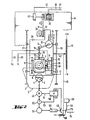
- Figures 1 and 2 illustrate the structure of an edge grinding machine guiding the grinding tool on a linear path.
- the glass sheet 1 whose periphery 2 must be ground is fixed on the plate 3 rotated about the axis 4 by a drive motor.
- the grinding tool constituted by a grinding wheel 6 resting on the motor shaft 7 is placed on the tool-carrying carriage 8.
- the tool-holder 8 is placed on the rails 9 and 10, movable relative to the axis of rotation 4 of the plate 3.
- the rails 9, 10 any other system ensuring a linear or substantially linear movement without too much friction for example, the tool holder 8 can be placed on articulated parallelograms, the sliding bearings 9, 10, here represented, then having to be replaced by the pivoting bearings of the articulated parallelogram.
- the connecting rod 12 is articulated to the tool holder 8, it transmits to the latter the grinding pressure exerted by the pressing device 13.
- the pressing device 13 is constituted by a so-called constant torque motor, ie a low inertia DC motor. and with a flat air gap, the torque of which is transmitted to the tool holder 8 by the crank 14, the connecting rod 15 articulated on the crank 14, the force sensor 16 and finally the connecting rod 12.
- the motor or pressing device 13 applies the grinding wheel 6 against the edge 2 of the glass sheet 1 according to an adjustable force.
- the grinding pressure exerted by the grinding wheel 6 is adjusted by a regulation circuit.
- the sensor 17 arranged perpendicular to the sensor 16 is used to determine the effective value of the grinding pressure.
- the edge 2 of the glass sheet constantly changing its relative position during the rotation of the glass around the axis 4 and therefore its point of impact on the grinding wheel 6, for the determination of the effective grinding pressure, we provides the two force sensors 16, 17, the sensor 16 measuring the pressure component parallel to the direction of movement of the tool holder 8 and the sensor 17 the pressure component acting perpendicular to this sensor 17.
- the voltage U 1 delivered by the sensor 16 which transforms the pressure measured into a voltage, and the voltage U 2 delivered by the force sensor 17 supply respectively via the lines 20 and 21 a regulation circuit described below in detail using FIG. 3 Via lines 23 and 24 the associated regulation amplifier supplies the constant torque motor 13 with a direct voltage adjusted in accordance with the set value.
- the positioning motor 30 is placed on the frame 34 of the machine.
- the positioning motor 30 is supplied by lines 36, 37 with a regulated voltage and makes part of a regulation circuit also detailed in FIG. 3.
- This regulation circuit includes a distance-voltage converter, for example a linear potentiometer 39 disposed on the carriage 26 and at one end of which a positive voltage is applied by example + 10V, while at the other end is applied a negative voltage of for example -10V.
- the cursor 40 rubbing on the potentiometer 39 is placed on the tool holder 8.
- the voltage taken by the cursor 40 of the potentiometer 39 is transmitted by line 41 as the reference voltage of the regulation amplifier, while the effective value is taken from the tachometer machine 42 coupled with the positioning motor 30 and driven by line 43 to the regulation amplifier.
- the motor control circuit 45 has mounted on the frame 34 of the machine, a linear potentiometer 46, on which the cursor 47 placed on the carriage 26 collects the reference voltage led to the regulation amplifier 50 by the line 48 and the switch 49.
- the effective voltage supplied by the angular sensor 52 coupled to the drive shaft of the motor 45, feeds by the line 53 the regulation amplifier.
- the regulated supply voltage is finally carried by line 51 to motor 45.
- the rotation pulse generator 54 coupled with the shaft of the plate 3 or of the drive motor 45, is connected to a programmable counter 55, that is to say provided with a preselector.
- the preset counter 55 is used to program the angular deviation of the plate 3 for the entire duration of the grinding operation.
- the regulation circuits of the constant torque motor 13 of the pressing device and of the positioning motor 30 are described with reference to the diagram of the connections shown in FIG. 3.
- the control voltages U 1 and U 2 coming from the force sensors 16, 17 supply via the lines 20, 21 a circuit 56 which calculates from the two voltages U, and U 2 the effective voltage U lst corresponding to the relation
- This effective voltage supplies via line 57 the regulating amplifier 58 which also receives via line 59 the regulated reference voltage for example by means of potentiometer 60.
- a current limiter 62 is inserted.
- This resistor 62 has the function of simulating an electromotive force for the regulation amplifier 58 during operation, the constant torque motor 13 not supplying force electromotive.
- a load resistor 64 is coupled by the switch 63 in parallel with the constant torque motor 13.
- the switch 63 is closed at the start of the grinding operation, that is to say during the start-up phase and is intended reduce the voltage supplied to the constant torque motor 13, so that the contact between the grinding tool and the edge of the glass sheet takes place smoothly. After this start-up phase, that is to say when the grinding operation proper begins, the switch is again open.
- the movements of the tool holder 8 generated by the constant torque motor 13 cause the cursor 40 placed on this tool holder 8 to move along the potentiometer 39.
- On one side of the potentiometer 39 there is a positive voltage by example + 10V and on the other a negative voltage of for example -10V.
- the cursor 40 rests in the middle of the potentiometer so that a voltage of + 0V is applied to the cursor 40. If the cursor 40 is moved in one direction or another, it is then applied a positive or negative voltage depending on the direction of movement of the cursor, voltage used as a reference value by the control amplifier 66 supplied by line 41.
- the angular sensor 52 mechanically coupled to the positioning motor, supplies the regulation amplifier 66 with its effective voltage.
- the operating voltage passes through the lines 36, 37 from the regulation amplifier 66 to the positioning motor 30.
- a load resistor 68 is mounted with the switch 67 which, like the resistor 64 is switched on during the start-up phase of the operation and switched off as soon as the actual grinding begins.
- the current limiter 69 inserted on line 37 is short-circuited at the end of the start-up phase at the same time as the load resistor 68, using the switch 67.
- the tool holder When the machine is started, the tool holder is first of all placed in the extreme position by the constant torque motor 13, owing to the fact that no effective voltage is supplied by the force sensors 16,17 as long that the grinding wheel 6 is not in contact with the edge of the glass sheet.
- the potentiometer 39 In this extreme position of the tool holder 8, the potentiometer 39 is out of travel, consequently the positioning motor 30 receives a maximum tension and the carriage 26 is moved towards the glass sheet 1 with maximum speed.
- the adjustment operation of the constant torque motor 13 begins upon contact between the grinding wheel 6 and the edge of the glass sheet. Simultaneously, the tool holder 8 moves back on the carriage 26 and the cursor 40 oscillates around its central position on the potentiometer 39 and adjusts the positioning motor 30.
- the speed of rotation of the turntable 3 is regulated only with the potentiometer 46 mounted on the plate 34 and whose cursor 4 is placed on the carriage 26. So that the regulation of the motor 45 driving the turntable 3 is obtained only during the actual grinding operation, simply on the angular deviation programmed using a preset counter, the cursor 47 is connected to the input setpoint of the regulation amplifier 50 by a switch 49 controlled by the preset counter 55.
- FIG. 4 differs from that shown in Figures 1 and 2 simply by the fact that the grinding tool, schematically represented by the grinding wheel 6, is not disposed on a tool carriage with linear movements , but is placed at the end of an oscillating arm 71 in rotation about the axis 72, the grinding tool 6 thus describing a circle passing through the axis of rotation 4 of the plate 3.
- the positioning motor 30 communicates to the plate 73 the rotational movement around the angular difference E necessary for positioning.
- the body of the constant torque motor 13, formed by a low inertia DC motor with a flat gap is fixed concentrically around the axis 72, on the plate 73 driven in rotation, thus the motor 13 accompanies the movements controlled by the positioning motor 30.
- the rotor of the constant torque motor 13 actuates the articulated arm 71.
- the motor 13 produces the regulated grinding pressure
- the regulation circuit again comprises two force sensors 16,17 arranged between the articulated arm 71 and the tool holder as well as a computer assembly 56, a regulation amplifier 58 and a reference potentiometer 60.
- the regulation of the positioning motor 30 is again obtained by the regulation cycle comprising the potentiometer 39 giving the setpoint voltage, the regulation amplifier 66 and the tachometer machine 42, generating the effective voltage.
- the potentiometer 39 is in this case formed by a rotary potentiometer so that the resistance body of the potentiometer 39 is coupled with the plate 73 and that the cursor 40 is coupled with the articulated arm 71.
- the control of the plate 73 by the positioning motor 30 and the regulation of the grinding pressure by the constant torque motor 13 are driven exactly as previously described for FIG. 3.
- the speed of rotation of the plate 3 is also regulated in accordance with what has been described for FIG. 2, except that in this case, the potentiometer 46 giving the set value is also formed by a rotary potentiometer whose cursor 47 is coupled to the axis of rotation 72 of the articulated arm.
- the switch 49 is again controlled by the preset counter 59, as well as the switch 72, which when the grinding operation has been carried out, brings the voltage passing through the line 72 as an input setpoint of the amplifier. regulation 58 so that the constant torque motor 13 of the grinding tool is moved away from the edge of the glass sheet.
- the setpoint voltage used for regulating the grinding pressure and supplying the regulating amplifier 58 via line 59 can in certain cases be modified according to a preset program. Such a modification of the grinding pressure during grinding is for example necessary when it is necessary to grind glass sheets having acute or rounded angles. In these cases, a lower grinding pressure should be used for the angles.
- a suitable programming device comprises a series of potentiometers adjusted according to different set values which, depending on the position of the grinding tool along the periphery of the glass sheet, are switched one after the other and thus provide different setpoint values on line 59. Such a programming device is described in detail in patent publication EP 0 084 506.
Landscapes
- Engineering & Computer Science (AREA)
- Chemical & Material Sciences (AREA)
- Ceramic Engineering (AREA)
- Inorganic Chemistry (AREA)
- Mechanical Engineering (AREA)
- Grinding And Polishing Of Tertiary Curved Surfaces And Surfaces With Complex Shapes (AREA)
- Constituent Portions Of Griding Lathes, Driving, Sensing And Control (AREA)
- Finish Polishing, Edge Sharpening, And Grinding By Specific Grinding Devices (AREA)
- Machine Tool Units (AREA)
Claims (7)
Priority Applications (1)
| Application Number | Priority Date | Filing Date | Title |
|---|---|---|---|
| AT85401278T ATE53524T1 (de) | 1984-06-30 | 1985-06-25 | Schleifmaschine mit einem regelkreis zum positionieren des werkzeugschlittens. |
Applications Claiming Priority (2)
| Application Number | Priority Date | Filing Date | Title |
|---|---|---|---|
| DE3424258 | 1984-06-30 | ||
| DE3424258A DE3424258C2 (de) | 1984-06-30 | 1984-06-30 | Maschine zum Kantenschleifen von Glasscheiben |
Publications (3)
| Publication Number | Publication Date |
|---|---|
| EP0168311A2 EP0168311A2 (de) | 1986-01-15 |
| EP0168311A3 EP0168311A3 (en) | 1987-12-09 |
| EP0168311B1 true EP0168311B1 (de) | 1990-06-13 |
Family
ID=6239608
Family Applications (1)
| Application Number | Title | Priority Date | Filing Date |
|---|---|---|---|
| EP85401278A Expired - Lifetime EP0168311B1 (de) | 1984-06-30 | 1985-06-25 | Schleifmaschine mit einem Regelkreis zum Positionieren des Werkzeugschlittens |
Country Status (5)
| Country | Link |
|---|---|
| US (1) | US4648210A (de) |
| EP (1) | EP0168311B1 (de) |
| JP (1) | JPS6130371A (de) |
| AT (1) | ATE53524T1 (de) |
| DE (2) | DE3424258C2 (de) |
Families Citing this family (13)
| Publication number | Priority date | Publication date | Assignee | Title |
|---|---|---|---|---|
| IT1190474B (it) * | 1986-02-04 | 1988-02-16 | Siv Soc Italiana Vetro | Macchina perfezionata per la molatura del bordo di lastre di vetro,particolarmente vetrature per automobili |
| US4881347A (en) * | 1988-01-27 | 1989-11-21 | Petrin Mario | Ski repairing machine |
| US5040342A (en) * | 1988-10-11 | 1991-08-20 | Ppg Industries, Inc. | Method and apparatus for processing glass sheets |
| EP0673715B1 (de) * | 1992-12-18 | 1999-01-20 | Bando Kiko Co. Ltd. | Maschine zum bearbeiten einer glasplatte |
| US5807166A (en) * | 1994-07-21 | 1998-09-15 | Bando Kiko Co., Ltd. | Glass-plate working machine |
| US6257957B1 (en) | 1999-12-01 | 2001-07-10 | Gerber Coburn Optical Inc. | Tactile feedback system |
| EP1747846A1 (de) * | 2005-07-25 | 2007-01-31 | Rollomatic S.A. | Verfahren und Vorrichtung zum Messen einer Schneidkante zum Schleifen |
| SE529606C2 (sv) | 2006-02-10 | 2007-10-02 | Tj Utveckling Ab | Verktygsinställare för en slipmaskin |
| US20100248594A1 (en) * | 2009-03-31 | 2010-09-30 | Darrel Nish | Setup tool for grinder sharpening jigs |
| DE102016110651A1 (de) * | 2016-06-09 | 2017-12-14 | Bystronic Lenhardt Gmbh | Vorrichtung und Verfahren zum Besäumen von Glastafeln |
| CN109702585A (zh) * | 2018-12-16 | 2019-05-03 | 浙江工业大学 | 一种用于马桶盖的恒力矩自动修边装置 |
| CN109366288B (zh) * | 2018-12-16 | 2024-03-01 | 浙江工业大学 | 一种用于马桶圈的恒力矩自动修边装置 |
| CN116572112B (zh) * | 2023-07-14 | 2023-09-12 | 盐城市大丰区礼盛新材料科技有限公司 | 一种循迹式异形玻璃磨边装置 |
Citations (1)
| Publication number | Priority date | Publication date | Assignee | Title |
|---|---|---|---|---|
| EP0084505A2 (de) * | 1982-01-20 | 1983-07-27 | Saint Gobain Vitrage International | Steuerungsverfahren für eine Maschine zum Schleifen der Kanten von Glasplatten und Vorrichtungen zum Ausführen dieses Verfahrens |
Family Cites Families (19)
| Publication number | Priority date | Publication date | Assignee | Title |
|---|---|---|---|---|
| US3062996A (en) * | 1960-03-29 | 1962-11-06 | Gen Electric | Tracer control system |
| US3100954A (en) * | 1962-03-20 | 1963-08-20 | Lella Paul Di | Grinding machine |
| US3274736A (en) * | 1964-03-20 | 1966-09-27 | Sun Tool & Machine Co | Edge tooling apparatus |
| US3553903A (en) * | 1967-07-31 | 1971-01-12 | Goodyear Tire & Rubber | Control system for a tire grinding machine |
| FR1588348A (de) * | 1968-10-14 | 1970-04-10 | ||
| GB1256815A (de) * | 1969-03-04 | 1971-12-15 | ||
| GB1387113A (en) * | 1971-03-30 | 1975-03-12 | Cranfield Inst Of Tech | Speed control system for grinding machines |
| US3827189A (en) * | 1973-04-10 | 1974-08-06 | Engelhard Min & Chem | Sheet glass seaming machine |
| US3828477A (en) * | 1973-05-07 | 1974-08-13 | Bendix Corp | Closed loop grinder infeed control system w/automatic compensation for wheel diameter changes due to dressing operations |
| US3939610A (en) * | 1973-07-30 | 1976-02-24 | Shatai Kogiyo Co. Ltd. | Device and method of grinding metallic molds and products automatically |
| DE2517001A1 (de) * | 1975-04-17 | 1976-10-21 | Buderus Eisenwerk | Verfahren und vorrichtung zur regelung des vorschubs einer schleifscheibe |
| DE2646062C3 (de) * | 1976-10-13 | 1979-08-09 | Vereinigte Glaswerke Gmbh, 5100 Aachen | Numerisch gesteuerte Modellschneidemaschine für Glasscheiben |
| US4228617A (en) * | 1977-12-31 | 1980-10-21 | Bando Kiko Co., Ltd | Method for grinding glass plates and the like through numerical control and beveling machine therefor |
| JPS5493288A (en) * | 1977-12-31 | 1979-07-24 | Bando Kiko Co | Glass chamfering machine |
| JPS56126567A (en) * | 1980-03-07 | 1981-10-03 | Hitachi Ltd | Abnormal state detecting controller for automatic grinding work |
| DE3376631D1 (en) * | 1982-01-20 | 1988-06-23 | Saint Gobain Vitrage | Apparatus for grinding the edges of glass sheets |
| DE3301200C2 (de) * | 1982-01-20 | 1984-08-30 | Vereinigte Glaswerke Gmbh, 5100 Aachen | Maschine zum Kantenschleifen von Glasscheiben |
| DK14583A (da) * | 1982-01-20 | 1983-07-21 | Saint Gobain Vitrage | Fremgangsmaade og apparat til positionsstyring af vaerktoejet paa en kantbearbejdningsmaskine til glasplader |
| FR2545025A1 (fr) * | 1983-04-28 | 1984-11-02 | Baudin Sa Ets | Machine destinee au bordage des feuilles de verre ou de glace chantournees |
-
1984
- 1984-06-30 DE DE3424258A patent/DE3424258C2/de not_active Expired
-
1985
- 1985-06-25 EP EP85401278A patent/EP0168311B1/de not_active Expired - Lifetime
- 1985-06-25 AT AT85401278T patent/ATE53524T1/de not_active IP Right Cessation
- 1985-06-25 DE DE8585401278T patent/DE3578142D1/de not_active Expired - Fee Related
- 1985-06-27 JP JP14147785A patent/JPS6130371A/ja active Pending
- 1985-06-27 US US06/749,959 patent/US4648210A/en not_active Expired - Fee Related
Patent Citations (1)
| Publication number | Priority date | Publication date | Assignee | Title |
|---|---|---|---|---|
| EP0084505A2 (de) * | 1982-01-20 | 1983-07-27 | Saint Gobain Vitrage International | Steuerungsverfahren für eine Maschine zum Schleifen der Kanten von Glasplatten und Vorrichtungen zum Ausführen dieses Verfahrens |
Also Published As
| Publication number | Publication date |
|---|---|
| ATE53524T1 (de) | 1990-06-15 |
| DE3578142D1 (de) | 1990-07-19 |
| US4648210A (en) | 1987-03-10 |
| EP0168311A2 (de) | 1986-01-15 |
| JPS6130371A (ja) | 1986-02-12 |
| DE3424258C2 (de) | 1986-12-11 |
| EP0168311A3 (en) | 1987-12-09 |
| DE3424258A1 (de) | 1986-01-23 |
Similar Documents
| Publication | Publication Date | Title |
|---|---|---|
| EP0084506A2 (de) | Verfahren und Vorrichtung zur Positionierung einer Maschine zur Bearbeitung der Kanten von Glasplatten | |
| EP0168311A2 (de) | Schleifmaschine mit einem Regelkreis zum Positionieren des Werkzeugschlittens | |
| EP1982783B1 (de) | Bearbeitungsmaschine | |
| EP0685296B1 (de) | Luftangetriebene Werkzeugmaschine | |
| EP0084505A2 (de) | Steuerungsverfahren für eine Maschine zum Schleifen der Kanten von Glasplatten und Vorrichtungen zum Ausführen dieses Verfahrens | |
| FR2644718A1 (fr) | Dispositif de reetalonnage d'une machine a meuler les verres ophtalmiques pour rattraper l'usure de la meule | |
| CA2087348C (fr) | Dispositif de support et de positionnement d'un microscope | |
| EP0210080B1 (de) | Verfahren und Einrichtung zur Bearbeitung eines hohlen Werkstückes durch Fräsung entlang einer vorbestimmten Linie | |
| EP0114141A2 (de) | Verfahren zur automatischen Steuerung einer Schleifmaschine mit drehbarem Schleifkopf zum Schleifen von Glasplattenrändern und Vorrichtung zur Anwendung desselben | |
| JP2004298985A (ja) | レンズ球面研磨装置 | |
| EP0074453A1 (de) | Verfahren und Maschine zur Herstellung von Schraubennahtröhren aus Karton, und Röhren auf diese Art hergestellt | |
| FR2481635A1 (fr) | Machine automatique a meuler et biseauter les verres de lunettes | |
| FR2460762A1 (fr) | Dispositif pour la commande de l'orientation d'un outil ou d'un element analogue par rapport a une piece | |
| FR2460182A1 (fr) | Dispositif permettant d'usiner des cames avec precision, et avec une vitesse de coupe constante | |
| CH616881A5 (en) | Set of rotary cylinders, particularly for a printing press | |
| EP0707527B1 (de) | Schneidmaschine ausgerüstet mit einem rotierenden rundschneidmesser zum schneiden eines biegsamen materials in form eines einzelnen blattes oder eines kleinen blattstapels, sowie verfahren zur einstellung einer solchen maschine | |
| CH683600A5 (fr) | Machine d'usinage par électro-érosion. | |
| EP0349438B1 (de) | Verfahren und Vorrichtung für die Identifizierung eines Schreibgerätes | |
| EP0499652B1 (de) | Drehmaschine zur Erzeugen asphärischer Oberflächen auf Werkstücken | |
| FR2664191A1 (fr) | Appareil d'usinage de contours en materiau tendre et procede d'usinage automatique utilisant un tel appareil. | |
| EP0765955B1 (de) | Mechanische Schwingvorrichtung, insbesondere Textilmaschinenhackerkamm dessen Schwingungen mittels eines monofasen Induktionsmotors instandgesetzt sind | |
| JP4446534B2 (ja) | 断裁機 | |
| EP0084504B1 (de) | Apparat zum Schleifen von Glaskanten | |
| EP0478872A1 (de) | Festonstickmaschine mit einer Vorrichtung zum automatischen Positionieren eines Musternockens | |
| FR2484393A1 (fr) | Dispositif de decoupe automatique d'une feuille de verre et procede s'y rapportant |
Legal Events
| Date | Code | Title | Description |
|---|---|---|---|
| PUAI | Public reference made under article 153(3) epc to a published international application that has entered the european phase |
Free format text: ORIGINAL CODE: 0009012 |
|
| AK | Designated contracting states |
Designated state(s): AT BE CH DE FR GB IT LI LU NL SE |
|
| PUAL | Search report despatched |
Free format text: ORIGINAL CODE: 0009013 |
|
| AK | Designated contracting states |
Kind code of ref document: A3 Designated state(s): AT BE CH DE FR GB IT LI LU NL SE |
|
| 17P | Request for examination filed |
Effective date: 19871114 |
|
| 17Q | First examination report despatched |
Effective date: 19890111 |
|
| RAP1 | Party data changed (applicant data changed or rights of an application transferred) |
Owner name: VEGLA VEREINIGTE GLASWERKE GMBH Owner name: SAINT-GOBAIN VITRAGE INTERNATIONAL |
|
| GRAA | (expected) grant |
Free format text: ORIGINAL CODE: 0009210 |
|
| AK | Designated contracting states |
Kind code of ref document: B1 Designated state(s): AT BE CH DE FR GB IT LI LU NL SE |
|
| REF | Corresponds to: |
Ref document number: 53524 Country of ref document: AT Date of ref document: 19900615 Kind code of ref document: T |
|
| REF | Corresponds to: |
Ref document number: 3578142 Country of ref document: DE Date of ref document: 19900719 |
|
| ITF | It: translation for a ep patent filed | ||
| GBT | Gb: translation of ep patent filed (gb section 77(6)(a)/1977) | ||
| PLBE | No opposition filed within time limit |
Free format text: ORIGINAL CODE: 0009261 |
|
| STAA | Information on the status of an ep patent application or granted ep patent |
Free format text: STATUS: NO OPPOSITION FILED WITHIN TIME LIMIT |
|
| 26N | No opposition filed | ||
| ITTA | It: last paid annual fee | ||
| PGFP | Annual fee paid to national office [announced via postgrant information from national office to epo] |
Ref country code: GB Payment date: 19920507 Year of fee payment: 8 |
|
| PGFP | Annual fee paid to national office [announced via postgrant information from national office to epo] |
Ref country code: CH Payment date: 19920629 Year of fee payment: 8 |
|
| PGFP | Annual fee paid to national office [announced via postgrant information from national office to epo] |
Ref country code: NL Payment date: 19920630 Year of fee payment: 8 |
|
| PGFP | Annual fee paid to national office [announced via postgrant information from national office to epo] |
Ref country code: DE Payment date: 19920722 Year of fee payment: 8 |
|
| PGFP | Annual fee paid to national office [announced via postgrant information from national office to epo] |
Ref country code: SE Payment date: 19930317 Year of fee payment: 9 |
|
| PGFP | Annual fee paid to national office [announced via postgrant information from national office to epo] |
Ref country code: AT Payment date: 19930413 Year of fee payment: 9 |
|
| PGFP | Annual fee paid to national office [announced via postgrant information from national office to epo] |
Ref country code: BE Payment date: 19930428 Year of fee payment: 9 |
|
| PGFP | Annual fee paid to national office [announced via postgrant information from national office to epo] |
Ref country code: FR Payment date: 19930429 Year of fee payment: 9 |
|
| PGFP | Annual fee paid to national office [announced via postgrant information from national office to epo] |
Ref country code: LU Payment date: 19930511 Year of fee payment: 9 |
|
| PG25 | Lapsed in a contracting state [announced via postgrant information from national office to epo] |
Ref country code: GB Effective date: 19930625 |
|
| PG25 | Lapsed in a contracting state [announced via postgrant information from national office to epo] |
Ref country code: LI Effective date: 19930630 Ref country code: CH Effective date: 19930630 |
|
| EPTA | Lu: last paid annual fee | ||
| PG25 | Lapsed in a contracting state [announced via postgrant information from national office to epo] |
Ref country code: NL Effective date: 19940101 |
|
| NLV4 | Nl: lapsed or anulled due to non-payment of the annual fee | ||
| GBPC | Gb: european patent ceased through non-payment of renewal fee |
Effective date: 19930625 |
|
| REG | Reference to a national code |
Ref country code: CH Ref legal event code: PL |
|
| PG25 | Lapsed in a contracting state [announced via postgrant information from national office to epo] |
Ref country code: DE Effective date: 19940301 |
|
| PG25 | Lapsed in a contracting state [announced via postgrant information from national office to epo] |
Ref country code: LU Free format text: LAPSE BECAUSE OF NON-PAYMENT OF DUE FEES Effective date: 19940625 Ref country code: AT Effective date: 19940625 |
|
| PG25 | Lapsed in a contracting state [announced via postgrant information from national office to epo] |
Ref country code: SE Effective date: 19940626 |
|
| PG25 | Lapsed in a contracting state [announced via postgrant information from national office to epo] |
Ref country code: BE Effective date: 19940630 |
|
| BERE | Be: lapsed |
Owner name: SAINT-GOBAIN VITRAGE INTERNATIONAL Effective date: 19940630 |
|
| EUG | Se: european patent has lapsed |
Ref document number: 85401278.8 Effective date: 19950110 |
|
| PG25 | Lapsed in a contracting state [announced via postgrant information from national office to epo] |
Ref country code: FR Effective date: 19950228 |
|
| EUG | Se: european patent has lapsed |
Ref document number: 85401278.8 |
|
| REG | Reference to a national code |
Ref country code: FR Ref legal event code: ST |