EP0168558B1 - Procédé et dispositif pour la fabrication d'échangeurs de chaleur et/ou de matière comportant des tuyaux - Google Patents
Procédé et dispositif pour la fabrication d'échangeurs de chaleur et/ou de matière comportant des tuyaux Download PDFInfo
- Publication number
- EP0168558B1 EP0168558B1 EP85104437A EP85104437A EP0168558B1 EP 0168558 B1 EP0168558 B1 EP 0168558B1 EP 85104437 A EP85104437 A EP 85104437A EP 85104437 A EP85104437 A EP 85104437A EP 0168558 B1 EP0168558 B1 EP 0168558B1
- Authority
- EP
- European Patent Office
- Prior art keywords
- tubes
- insert
- tube
- mandrels
- injection
- Prior art date
- Legal status (The legal status is an assumption and is not a legal conclusion. Google has not performed a legal analysis and makes no representation as to the accuracy of the status listed.)
- Expired - Lifetime
Links
- 238000000034 method Methods 0.000 title claims description 62
- 238000002347 injection Methods 0.000 claims description 116
- 239000007924 injection Substances 0.000 claims description 116
- 239000012815 thermoplastic material Substances 0.000 claims description 41
- 238000001746 injection moulding Methods 0.000 claims description 37
- 239000000463 material Substances 0.000 claims description 34
- 239000002826 coolant Substances 0.000 claims description 20
- 238000001816 cooling Methods 0.000 claims description 20
- 239000000155 melt Substances 0.000 claims description 20
- 238000002844 melting Methods 0.000 claims description 15
- 230000008018 melting Effects 0.000 claims description 15
- 238000010438 heat treatment Methods 0.000 claims description 14
- -1 polypropylene Polymers 0.000 claims description 14
- 239000011148 porous material Substances 0.000 claims description 11
- 229920001169 thermoplastic Polymers 0.000 claims description 11
- 239000002033 PVDF binder Substances 0.000 claims description 10
- 229920002981 polyvinylidene fluoride Polymers 0.000 claims description 10
- 239000004743 Polypropylene Substances 0.000 claims description 9
- 229920001155 polypropylene Polymers 0.000 claims description 9
- 239000002184 metal Substances 0.000 claims description 7
- 229910052751 metal Inorganic materials 0.000 claims description 7
- 229920000642 polymer Polymers 0.000 claims description 6
- 238000004519 manufacturing process Methods 0.000 claims description 5
- 239000004033 plastic Substances 0.000 claims description 5
- 229920003023 plastic Polymers 0.000 claims description 5
- 239000004698 Polyethylene Substances 0.000 claims description 3
- 239000000203 mixture Substances 0.000 claims description 3
- 229920000573 polyethylene Polymers 0.000 claims description 3
- 229920001577 copolymer Polymers 0.000 claims description 2
- 230000003247 decreasing effect Effects 0.000 claims description 2
- 239000012768 molten material Substances 0.000 claims description 2
- BVKZGUZCCUSVTD-UHFFFAOYSA-L Carbonate Chemical compound [O-]C([O-])=O BVKZGUZCCUSVTD-UHFFFAOYSA-L 0.000 claims 1
- NBVXSUQYWXRMNV-UHFFFAOYSA-N fluoromethane Chemical compound FC NBVXSUQYWXRMNV-UHFFFAOYSA-N 0.000 claims 1
- 230000004927 fusion Effects 0.000 claims 1
- 239000004416 thermosoftening plastic Substances 0.000 claims 1
- 239000012778 molding material Substances 0.000 description 13
- 239000007789 gas Substances 0.000 description 6
- 239000000853 adhesive Substances 0.000 description 5
- 230000001070 adhesive effect Effects 0.000 description 5
- 239000003570 air Substances 0.000 description 5
- 230000002349 favourable effect Effects 0.000 description 5
- 239000012510 hollow fiber Substances 0.000 description 5
- 239000011248 coating agent Substances 0.000 description 4
- 238000000576 coating method Methods 0.000 description 4
- 238000006073 displacement reaction Methods 0.000 description 4
- 230000009172 bursting Effects 0.000 description 3
- 238000005266 casting Methods 0.000 description 3
- 239000000835 fiber Substances 0.000 description 3
- 239000010445 mica Substances 0.000 description 3
- 229910052618 mica group Inorganic materials 0.000 description 3
- 230000001681 protective effect Effects 0.000 description 3
- 230000000052 comparative effect Effects 0.000 description 2
- 230000003628 erosive effect Effects 0.000 description 2
- 239000000945 filler Substances 0.000 description 2
- 238000005470 impregnation Methods 0.000 description 2
- 238000003780 insertion Methods 0.000 description 2
- 230000037431 insertion Effects 0.000 description 2
- 239000007788 liquid Substances 0.000 description 2
- 239000003921 oil Substances 0.000 description 2
- 238000005192 partition Methods 0.000 description 2
- 229910052628 phlogopite Inorganic materials 0.000 description 2
- 239000004417 polycarbonate Substances 0.000 description 2
- 229920000515 polycarbonate Polymers 0.000 description 2
- 229920013745 polyesteretherketone Polymers 0.000 description 2
- 239000007787 solid Substances 0.000 description 2
- 239000007921 spray Substances 0.000 description 2
- XLYOFNOQVPJJNP-UHFFFAOYSA-N water Substances O XLYOFNOQVPJJNP-UHFFFAOYSA-N 0.000 description 2
- OKTJSMMVPCPJKN-UHFFFAOYSA-N Carbon Chemical compound [C] OKTJSMMVPCPJKN-UHFFFAOYSA-N 0.000 description 1
- 229920000049 Carbon (fiber) Polymers 0.000 description 1
- 229910000669 Chrome steel Inorganic materials 0.000 description 1
- RYGMFSIKBFXOCR-UHFFFAOYSA-N Copper Chemical compound [Cu] RYGMFSIKBFXOCR-UHFFFAOYSA-N 0.000 description 1
- 239000004952 Polyamide Substances 0.000 description 1
- 239000004695 Polyether sulfone Substances 0.000 description 1
- 229920002367 Polyisobutene Polymers 0.000 description 1
- 229910000831 Steel Inorganic materials 0.000 description 1
- 239000012080 ambient air Substances 0.000 description 1
- 239000010425 asbestos Substances 0.000 description 1
- 239000011324 bead Substances 0.000 description 1
- 239000004917 carbon fiber Substances 0.000 description 1
- 229910052802 copper Inorganic materials 0.000 description 1
- 239000010949 copper Substances 0.000 description 1
- 230000007423 decrease Effects 0.000 description 1
- 238000010586 diagram Methods 0.000 description 1
- YGANSGVIUGARFR-UHFFFAOYSA-N dipotassium dioxosilane oxo(oxoalumanyloxy)alumane oxygen(2-) Chemical compound [O--].[K+].[K+].O=[Si]=O.O=[Al]O[Al]=O YGANSGVIUGARFR-UHFFFAOYSA-N 0.000 description 1
- 239000004744 fabric Substances 0.000 description 1
- 230000004907 flux Effects 0.000 description 1
- 239000003365 glass fiber Substances 0.000 description 1
- 239000003292 glue Substances 0.000 description 1
- 239000010439 graphite Substances 0.000 description 1
- 229910002804 graphite Inorganic materials 0.000 description 1
- 230000017525 heat dissipation Effects 0.000 description 1
- 239000001307 helium Substances 0.000 description 1
- 229910052734 helium Inorganic materials 0.000 description 1
- SWQJXJOGLNCZEY-UHFFFAOYSA-N helium atom Chemical compound [He] SWQJXJOGLNCZEY-UHFFFAOYSA-N 0.000 description 1
- 239000004413 injection moulding compound Substances 0.000 description 1
- 238000009434 installation Methods 0.000 description 1
- 150000002739 metals Chemical class 0.000 description 1
- 239000000178 monomer Substances 0.000 description 1
- 229910052627 muscovite Inorganic materials 0.000 description 1
- 239000006223 plastic coating Substances 0.000 description 1
- 229920002492 poly(sulfone) Polymers 0.000 description 1
- 229920002647 polyamide Polymers 0.000 description 1
- 229920000728 polyester Polymers 0.000 description 1
- 229920006393 polyether sulfone Polymers 0.000 description 1
- 229920000915 polyvinyl chloride Polymers 0.000 description 1
- 230000005855 radiation Effects 0.000 description 1
- 230000003014 reinforcing effect Effects 0.000 description 1
- 229910052895 riebeckite Inorganic materials 0.000 description 1
- 238000007789 sealing Methods 0.000 description 1
- 239000011343 solid material Substances 0.000 description 1
- 229910001220 stainless steel Inorganic materials 0.000 description 1
- 239000010935 stainless steel Substances 0.000 description 1
- 239000007858 starting material Substances 0.000 description 1
- 239000010959 steel Substances 0.000 description 1
- 230000002459 sustained effect Effects 0.000 description 1
- 239000003760 tallow Substances 0.000 description 1
- 238000005496 tempering Methods 0.000 description 1
- BFKJFAAPBSQJPD-UHFFFAOYSA-N tetrafluoroethene Chemical group FC(F)=C(F)F BFKJFAAPBSQJPD-UHFFFAOYSA-N 0.000 description 1
- 238000009941 weaving Methods 0.000 description 1
- 238000003466 welding Methods 0.000 description 1
Images





Classifications
-
- B—PERFORMING OPERATIONS; TRANSPORTING
- B29—WORKING OF PLASTICS; WORKING OF SUBSTANCES IN A PLASTIC STATE IN GENERAL
- B29C—SHAPING OR JOINING OF PLASTICS; SHAPING OF MATERIAL IN A PLASTIC STATE, NOT OTHERWISE PROVIDED FOR; AFTER-TREATMENT OF THE SHAPED PRODUCTS, e.g. REPAIRING
- B29C45/00—Injection moulding, i.e. forcing the required volume of moulding material through a nozzle into a closed mould; Apparatus therefor
- B29C45/14—Injection moulding, i.e. forcing the required volume of moulding material through a nozzle into a closed mould; Apparatus therefor incorporating preformed parts or layers, e.g. injection moulding around inserts or for coating articles
- B29C45/14336—Coating a portion of the article, e.g. the edge of the article
-
- B—PERFORMING OPERATIONS; TRANSPORTING
- B01—PHYSICAL OR CHEMICAL PROCESSES OR APPARATUS IN GENERAL
- B01D—SEPARATION
- B01D63/00—Apparatus in general for separation processes using semi-permeable membranes
- B01D63/02—Hollow fibre modules
- B01D63/021—Manufacturing thereof
- B01D63/022—Encapsulating hollow fibres
- B01D63/0221—Encapsulating hollow fibres using a mould
-
- B—PERFORMING OPERATIONS; TRANSPORTING
- B01—PHYSICAL OR CHEMICAL PROCESSES OR APPARATUS IN GENERAL
- B01D—SEPARATION
- B01D63/00—Apparatus in general for separation processes using semi-permeable membranes
- B01D63/02—Hollow fibre modules
- B01D63/032—More than two tube sheets for one bundle
-
- B—PERFORMING OPERATIONS; TRANSPORTING
- B01—PHYSICAL OR CHEMICAL PROCESSES OR APPARATUS IN GENERAL
- B01D—SEPARATION
- B01D63/00—Apparatus in general for separation processes using semi-permeable membranes
- B01D63/06—Tubular membrane modules
- B01D63/061—Manufacturing thereof
-
- B—PERFORMING OPERATIONS; TRANSPORTING
- B29—WORKING OF PLASTICS; WORKING OF SUBSTANCES IN A PLASTIC STATE IN GENERAL
- B29C—SHAPING OR JOINING OF PLASTICS; SHAPING OF MATERIAL IN A PLASTIC STATE, NOT OTHERWISE PROVIDED FOR; AFTER-TREATMENT OF THE SHAPED PRODUCTS, e.g. REPAIRING
- B29C45/00—Injection moulding, i.e. forcing the required volume of moulding material through a nozzle into a closed mould; Apparatus therefor
- B29C45/14—Injection moulding, i.e. forcing the required volume of moulding material through a nozzle into a closed mould; Apparatus therefor incorporating preformed parts or layers, e.g. injection moulding around inserts or for coating articles
- B29C45/14598—Coating tubular articles
-
- B—PERFORMING OPERATIONS; TRANSPORTING
- B29—WORKING OF PLASTICS; WORKING OF SUBSTANCES IN A PLASTIC STATE IN GENERAL
- B29C—SHAPING OR JOINING OF PLASTICS; SHAPING OF MATERIAL IN A PLASTIC STATE, NOT OTHERWISE PROVIDED FOR; AFTER-TREATMENT OF THE SHAPED PRODUCTS, e.g. REPAIRING
- B29C45/00—Injection moulding, i.e. forcing the required volume of moulding material through a nozzle into a closed mould; Apparatus therefor
- B29C45/14—Injection moulding, i.e. forcing the required volume of moulding material through a nozzle into a closed mould; Apparatus therefor incorporating preformed parts or layers, e.g. injection moulding around inserts or for coating articles
- B29C45/14598—Coating tubular articles
- B29C45/14614—Joining tubular articles
-
- F—MECHANICAL ENGINEERING; LIGHTING; HEATING; WEAPONS; BLASTING
- F28—HEAT EXCHANGE IN GENERAL
- F28F—DETAILS OF HEAT-EXCHANGE AND HEAT-TRANSFER APPARATUS, OF GENERAL APPLICATION
- F28F21/00—Constructions of heat-exchange apparatus characterised by the selection of particular materials
- F28F21/06—Constructions of heat-exchange apparatus characterised by the selection of particular materials of plastics material
- F28F21/062—Constructions of heat-exchange apparatus characterised by the selection of particular materials of plastics material the heat-exchange apparatus employing tubular conduits
-
- F—MECHANICAL ENGINEERING; LIGHTING; HEATING; WEAPONS; BLASTING
- F28—HEAT EXCHANGE IN GENERAL
- F28F—DETAILS OF HEAT-EXCHANGE AND HEAT-TRANSFER APPARATUS, OF GENERAL APPLICATION
- F28F21/00—Constructions of heat-exchange apparatus characterised by the selection of particular materials
- F28F21/06—Constructions of heat-exchange apparatus characterised by the selection of particular materials of plastics material
- F28F21/067—Details
-
- Y—GENERAL TAGGING OF NEW TECHNOLOGICAL DEVELOPMENTS; GENERAL TAGGING OF CROSS-SECTIONAL TECHNOLOGIES SPANNING OVER SEVERAL SECTIONS OF THE IPC; TECHNICAL SUBJECTS COVERED BY FORMER USPC CROSS-REFERENCE ART COLLECTIONS [XRACs] AND DIGESTS
- Y10—TECHNICAL SUBJECTS COVERED BY FORMER USPC
- Y10S—TECHNICAL SUBJECTS COVERED BY FORMER USPC CROSS-REFERENCE ART COLLECTIONS [XRACs] AND DIGESTS
- Y10S264/00—Plastic and nonmetallic article shaping or treating: processes
- Y10S264/65—Processes of preheating prior to molding
Definitions
- the invention relates to a method for producing heat and / or mass exchangers which contain pipes by means of injection molding a thermoplastic material with the aid of an injection mold consisting of at least two parts, for example an upper and lower mold, and to a device for producing Heat and / or mass exchangers containing pipes with an injection mold consisting of at least two parts for performing this method.
- DE-OS 28 24 934 a method and a device for producing mass exchangers is known, in which a bundle of hollow fibers is inserted into a casting mold into which melted thermoplastic material is filled. After the thermoplastic material has solidified, the fiber bundle is removed from the mold and cut in the region of the solidified thermoplastic material. In this way, two tube sheets are created. If tube sheets are cast on both ends of the bundle of hollow fibers, a material exchanger has been created, in which only the necessary connections have to be made, and which may be inserted into a housing.
- this DE-OS 28 24 934 it is also stated that attempts have already been made to obtain tube sheets by pressure impregnation with polymeric compositions in each case at one end of the pre-cut hollow fiber bundle. However, this pressure impregnation would have the disadvantage that the extremely thin walls of the hollow fibers break or be crushed, and that the open thread ends easily clog.
- EP-A-22 234 glue metal tubes to a tube sheet by first inserting the metal tubes into the tube sheet and then coating the tube sheet from the outside with adhesive. To improve the adhesion of the adhesive, it can be exposed to increased pressure after coating.
- the metal tubes are also connected to each other between the two tube sheets by a large number of fins. With this type of connection, many operations are required, and curing the adhesive connection is very time-consuming. Coating the tube sheet with adhesive is also all the more time-consuming and requires more care, the more tubes are to be glued into a tube sheet.
- thermoplastic material with the aid of one of at least two parts, for example an upper and To provide existing mold under injection mold, which are particularly suitable when using thin-walled and / or easily deformable tubes, and by which a good connection of the tubes with the tube sheet is guaranteed.
- a method of the type mentioned at the outset which is characterized in that in the first part of the injection mold (upper or lower mold) there is an insert which is preferably made of plastic and can preferably be connected to the pipes by melting, the bottom of which is for each Pipe has a continuous opening, is used as a positioning element for the pipes in such a way that the insert is at least partially positively arranged in the first part of the injection mold, that a pipe is inserted into each opening of the insert, that a mandrel is inserted into each pipe, after which the injection mold is connected in such a way that the mandrels in the second part of the injection mold (lower or upper mold) are positioned non-positively and / or positively that the melted thermoplastic material is injected into the injection mold through an injection channel into the injection mold, the one etz and the tube ends formed cavity is injected that after cooling the thermoplastic material, which is at least initially still kept under pressure during cooling, the parts of the injection mold are separated, the mandre
- the insert is usually made of plastic, but it is sufficient if the insert consists of a different material and is provided with a sufficiently thick plastic coating at the points where the connection between the insert and the thermoplastic material or between the insert and the pipes to be manufactured.
- thermoplastic material usually being melted during injection molding and under high pressure in the cavity formed by the injection mold above the nozzle spray channel is injected.
- pressures of up to 80 bar are common. Higher pressures result depending on the composition of the thermoplastic material or the design of the injection mold.
- the finished process product for example the tube sheet
- the tube sheet can be post-treated, if appropriate after attaching further parts such as flanges, tubes, etc.
- irradiation with gamma, X-ray, high-frequency or ultraviolet radiation can take place, as a result of which the softening point of the injection-molded thermoplastic materials used can be increased.
- tubes includes all tubular bodies, such as tubes, hoses or hollow fibers.
- the cross-sectional shape of the tubes is not limited to circular cross-sections; the tubes can also have an elliptical or polygonal cross section, for example triangular, quadrangular, square, pentagonal, etc.
- the wall thickness of the pipes, which results from the outside and inside cross section of the pipes, can be the same or different over the circumference of the pipes.
- Outside and inside cross-section of the tubes can have the same or different cross-sectional shape.
- a tube may have a polygonal contour in the outer cross section and a circular or elliptical contour in the inner cross section.
- the inner cross section of the tubes can also have one or more continuous cavities.
- the outside and / or inside cross section of the tubes can also have knob-shaped elevations or ribs, so that when such tubes are used in a heat and / or material exchanger, the turbulence of the flow medium is increased, which causes an increase in efficiency.
- Pipes, for which the method according to the invention can be used particularly advantageously, generally consist of polymers.
- Suitable polymers are, for example, polyamides, polyesters, polycarbonates, polypropylenes, polyethylenes, polyisobutylenes, PVC, injection-moldable copolymers which contain tetrafluoroethylene monomers, polyvinylidene fluoride (PVDF), aromatic ether imides, polysulfone, polyether sulfone or polyester ether ketone (PEEK).
- PVDF polyvinylidene fluoride
- PEEK polyester ether ketone
- the tubes are advantageously inserted in such a way that a tube is inserted into each opening of the insert in such a way that the inside of the tube protrudes from the bottom of the insert.
- the pipes can be fixed against longitudinal displacement.
- the injection mold it is expedient for the injection mold to be tempered to cool the thermoplastic material.
- the temperature control of the injection mold can be accomplished via a bore running in the upper and / or lower mold, through which a temperature control medium, for example water, oil or gas, is passed.
- the inner surface of the injection mold and the outer surfaces of the mandrels have a smooth surface, are polished or are coated with a material which prevents adhesion between the tubes and the mandrels in order to prevent the injection molding compound or the tubes from sticking together to prevent the injection mold or the thorns.
- the bonding of the mandrels to the tubes can also be effectively avoided by cooling the mandrels during and / or after the injection molding process.
- the mandrels advantageously have continuous cavities through which a cooling medium is passed in order to cool the mandrels.
- a cooling medium can be used for this.
- a gas preferably air or helium
- the cooling medium can either be supplied to the mandrels via the injection mold, the outflow through the pipes, or room air can be drawn in via the mandrels.
- the method according to the invention is particularly characterized in that a plurality of tubes are first connected to tube groups, and the tube groups are inserted into corresponding through openings in the insert base.
- Hollow threads can, for example, be embedded in a fabric as weft threads, but flexible tubes can also be combined to form tube groups if they are twisted together.
- the process according to the invention is facilitated if the tubes are combined into tube groups parallel to the axis or almost parallel to the axis.
- This summary can advantageously be done, for example, in that the cross section of the tube groups perpendicular to the axis of the tubes then has the shape of a plate, for example a flat, profiled or spiral plate.
- the summary of the tubes can already be accomplished, for example, during the manufacture of the tubes.
- the pipes can be brought together while casting while still sticky, so that they stick together.
- Pipes of different cross-sections can also be combined into pipe groups.
- Plate-like structures which have a plurality of continuous cavities and thus, for example, the shape of tube plates, can be referred to in the sense of the invention either as tubes or as a tube group.
- These plate-shaped structures, which have a plurality of continuous cavities, can have the shape of a flat plate, but they can also take the form of a profiled or spiral plate. Examples of profiled and spiral plate shapes are shown in the figures and described in the description of the figures.
- the method according to the invention can be used excellently if tubes made of non-porous material or of porous material with a pore volume of up to 90% are used, the hydraulic diameter d of which is between 0.5 to 25 mm, preferably 0.5 to 15 mm. Another preferred range is 0.8 to 10 mm.
- the hydraulic diameter d h is defined as the quotient of the fourfold inner cross-sectional area divided by the wetted inner circumference (see also Dubbel, Taschenbuch für die Maschinenbau, 13th edition, 1970, page 314, paragraph 4). Since the hydraulic diameter d . based on the internal cross-section, the condition that the hydraulic diameter should be between 0.5 and 25 mm applies to tube groups or tube plates for the individual continuous cavity.
- the method according to the invention works particularly well if the wall thickness of the pipes at the thinnest point is about 5 to 25% of the hydraulic diameter d ,, having.
- the pipes made of non-porous or porous material with a pore volume of less than 50% are used, their hydraulic diameter d h is advantageously between 0.5 and 5 mm, preferably between 0.8 and 3 mm.
- Pipe wall thicknesses are preferred which have a value of about 7.5 to 17.5% of the hydraulic diameter d h at the thinnest point.
- the tubes, the inserts and the thermoplastic material used for injection molding are advantageously made of thermoplastic polymers. It is advantageous if these thermoplastic polymers, from which the tubes, the inserts and the thermoplastic material consist, at least in the areas in which the connection takes place, belong to the same type of polymer in terms of their basic structure. It is also particularly favorable if the tubes, the inserts and the thermoplastic material consist, at least in the areas in which the connection is made to one another, of thermoplastic polymers which have the same or almost the same melting point or melting range.
- the tightness and strength of the connection points between the tube and the tube sheet are influenced particularly favorably if at least the tubes are heated to a temperature T c before the injection of the thermoplastic material, which is below the melting point temperature or the average temperature of the melting range T m of the tube material, if the thermoplastic material heated to melt continues to a temperature T ; is heated, which is greater than T " , and if the temperature differences T r -T m and T m -T c are chosen such that when the melt is injected, the tubes are briefly heated to such an extent that they are in the region of the openings of the insert At least over a length that corresponds to the wall thickness of the tubes, fuse firmly with the insert.
- T m corresponds to the melting point temperature for polymers that have a pronounced melting point.
- a particularly good strength of the connection point between the tube and the tube sheet is achieved in that the temperature differences T i -T m and T m -T c are chosen such that when the melt is injected the tubes are briefly heated to such an extent that they are about the melt the entire length of the openings in the insert firmly into the insert.
- the temperature difference T i -T m is advantageously chosen between 20 and 90 ° C., preferably between 30 and 70 ° C. According to the invention, it was found that a particularly firm and permanent connection between tubes and tube sheet is achieved in this temperature difference range. This applies in particular if the temperature difference T m -T c is selected to be at least equal to T i -T m and at most equal to T m -40 ° C. At the beginning of the injection process or in the course of the injection of the melt, cooling of the pipes must then be started.
- the selected temperatures of the tubes to which the tubes are to be heated or cooled, before, during and after the injection of the melt, are advantageously determined using a gas, which is passed through the cavities of the mandrels.
- PVDF polypropylene
- polyethylene polyethylene
- polycarbonate has proven particularly useful as a thermoplastic material for pipes, inserts and spray material.
- the object of the invention is also achieved by a device for producing heat and / or mass exchangers which contain pipes, with an injection mold consisting of at least two parts for carrying out the method according to the invention, which is characterized in that an insert is used in the first part of the injection mold for positioning the mandrels is arranged at least partially in a form-fitting manner that the first part of the injection mold has a common opening for all pipes and the insert has a through-opening for each pipe, the inner dimension of which corresponds to the outer dimension of the respective pipe, and that the second part of the injection mold facilities for receiving a number of mandrels, the outer dimension of which corresponds to the inner dimension of the respective tube, and the number of which corresponds to that of the tubes of the heat exchanger and / or mass exchanger to be produced, and that an injection channel is incorporated into the injection mold .
- the mandrels can be inserted individually or in groups into the tubes, the mandrels having a shoulder, up to which the mandrels can be inserted, after which the second part of the injection mold is placed on the first part in such a way that the mandrels are provided for this purpose Openings or bores of the second part of the injection mold are positioned.
- the mandrels can also be connected to one another in groups in the positioning area of the mandrels.
- the mandrels can also be fastened in the second part of the injection mold. In such an embodiment, the mandrels are inserted into the openings of the tubes when the second part is placed on the first part of the injection mold.
- the first and / or second part of the injection mold contains a cooling device.
- this cooling device can be a bore running in the first part or in the second part, through which the cooling medium, for example cooled water, cooled gas or cooled air, is passed.
- the first and / or the second part of the injection mold can also contain a heating device.
- the heating device and cooling device can also be formed by the same device.
- Heating or cooling of the mandrels can advantageously be accomplished in that the mandrels each have a continuous cavity, all cavities of the mandrels being connected to a medium distributor in the second part of the injection mold.
- This medium distributor can simultaneously be the heating or cooling device of the second part of the injection mold.
- the use in the first part of the injection mold which is part of the tube sheet of the heat and / or mass exchanger produced after the process according to the invention has ended, preferably consists of a thermoplastic polymer, while all other parts of the injection mold (part 1, part 2, Spines, etc.) are made of metal. This guarantees good heat supply and heat dissipation in all parts of the injection mold.
- suitable metals are stainless steel, case hardening steel or copper.
- the through openings of the insert advantageously have a clearance fit with respect to the outer dimensions of the tubes.
- the term clearance fit is defined in DIN 7812 Sheet 2. It is also expedient if the outer dimensions of the mandrels have a clearance fit with the inner dimensions of the tubes.
- the mandrels are tapered at their free ends.
- the free end of the mandrels is that end of the mandrels which is not positioned or fastened in the second part of the injection mold and which is provided for insertion into the tubes.
- the mandrel ends either have tips, are frustoconical or have a differently shaped taper.
- the length of the mandrels is expediently chosen such that they protrude from the openings of the insert when the injection mold is assembled. The length of the mandrels should therefore be greater than the thickness of the tube sheet to be produced, which ensures that the tubes are supported over the entire length of the embedding in the tube sheet.
- the mandrels advantageously have a slight taper towards the free end, which makes it easier to pull the mandrels out of the pipes after the injection molding process has ended.
- the mandrels in such a way that, with the exception of the section which is received by the second part of the injection mold, they have a decreasing diameter toward the free end.
- the tubes in the region of the tube sheet can be plastically deformed or melted and in this way assume the shape of the mandrels.
- the tube ends can be shaped into funnels, as a result of which favorable flow conditions in the finished heat and / or mass exchanger can be set in the region of the tube sheet.
- the insert has at least one circumferential groove on its inside.
- ge flows molten material in this groove so that even in the event of high stress on the tube sheet, for example due to extreme thermal expansion of the tubes, in the finished heat and / or material exchanger it is prevented that the thermoplastic material is pressed out of the insert.
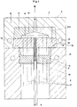
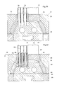
- FIG. 1 schematically shows a device according to the invention for producing a tubular material and / or heat exchanger in the assembled state, pipes already being used in this device.
- 1 denotes the upper shape and 2 the lower shape.
- a cylindrical insert is inserted into the lower mold 2, the bottom of which has a through opening 10 for each tube, only one through opening being shown in the schematic representation of the figure.
- a tube 8 is inserted into the through opening 10 of the cylindrical insert 3 up to the upper edge of the cylindrical insert 3.
- the tube 8 is shown in section in the area of the cylindrical insert and in plan view in the lower area of the lower mold 2. Further tubes 8, as indicated for example in FIG. 1, are inserted along the dash-dotted lines 11.
- the upper mold 1 consists of a holder 4, in which the coolant distributor 5 and a mandrel holder 6 are inserted.
- the holder 4, coolant distributor 5 and mandrel holder 6 can be connected, for example, by screws which are arranged in a place which is indicated by dash-dotted lines 130.
- mandrels 7 are inserted, which have a continuous cavity.
- only one mandrel 7 is shown, for example further mandrels 7 can be arranged along the dash-dotted lines 11.
- the free end of the mandrel 7 is truncated pyramid-shaped.
- the length of the mandrels is chosen such that the free end of the mandrels protrudes into the opening of the insert 3, so that the length of the mandrels protruding from the upper shape is greater than the thickness of the tube sheet to be produced.
- About the coolant inflow - shown in the figure with arrow B - and the coolant distributor 5 can be supplied to the continuous cavities of the mandrels 7 cooling medium which pours into the tubes after leaving the mandrels and flows out at the rear end of the tubes.
- the direction of flow of the cooling medium can also be selected in the direction opposite to arrow B if a suction device is connected to the coolant distributor 5. When vacuuming, the ambient air surrounding the injection mold is then used as the coolant.
- the insert 3 has a groove 9 on the outer surface, into which the lower mold 2 engages in order to achieve an axial fixation of the insert 3.
- the lower mold 2 is constructed in two parts (not shown in the figure).
- a gating channel 12 is incorporated into the upper mold, through which the melted material for producing the tube sheet in the direction of arrow A is pressed under high pressure into the inner space 15 formed by the insert 3, the mandrel holder 6 (upper mold) and the tubes 8. Bores 13 are provided in the holder 4 of the upper mold 1 and holes 14 are provided in the lower mold 2, through which coolants can be passed.
- FIGS. 2 to 7 and FIGS. 28 to 30 Arrangement forms of tubes in tube sheets, of material and / or heat exchangers can be produced with the device shown schematically in FIG. 1 are shown for example in FIGS. 2 to 7 and FIGS. 28 to 30.
- the outer cross section of the tube sheets according to FIGS. 2 to 7 is circular in each case.
- the tube sheets are designated 16 and the tubes 17.
- the continuous tubes 17 can be arranged in the tube sheet 16 in various ways.
- the continuous tubes 17 are arranged in the tube sheet 16 within a hexagonal contour.
- the continuous tubes 17 are arranged in the tube sheet 16 within a square contour.
- FIG. 5 shows a linear arrangement, in FIG. 6 a wavy arrangement and in FIG. 7 a spiral arrangement of the continuous tubes 17 in the tube sheet 16.
- the 28 to 30 show different cross-sectional shapes of tubes which only have a continuous cavity.
- the tube 53 with a continuous cavity 54 according to FIG. 28 has a circular outer cross section and a circular inner cross section.
- the outer and inner cross sections can be arranged symmetrically, as shown in FIG. 28, or asymmetrically. With an asymmetrical arrangement of the outer and inner cross-section, the tube 53 has different wall thicknesses on the circumference.
- the tube 55 according to FIG. 29 has a square outer cross section, but the corners are rounded.
- the continuous cavity 56 of this tube 55 also has a square inner cross section with rounded corners.
- a circular inner cross section could also be present in the tube 55 according to FIG. 29.
- the inner cross section could also be square and the outer cross section circular.
- the outer and / or inner cross section can have an elliptical shape, as shown in FIG. 30 as a tube 57 with a continuous hollow frame 58.
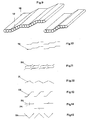
- FIGS. 9 to 27 and 39 show two plate tube groups 18 which represent profiled plates. The shape of the profile could largely be described as a step. Through the continuous cavities 19 can be seen that the plates 18 are each composed of several tubes.
- FIGS. 10 to 15 Several profile shapes of tube plates are shown in FIGS. 10 to 15, the profile shape in these figures only being indicated as lines.
- the profiles can be described as follows: profile 18 according to FIG. 10: stair-shaped (as shown in more detail in FIG. 9), profile 20 according to FIG. 11: panels with angled edges, profile 21 according to FIG. 12: angled panel in the shape of a roof, profile 22 according to FIG.
- Such profile plates are arranged several times next to each other in order to get a large exchange surface. This is indicated in FIG. 8, in which the profile according to FIGS. 9 and 10 was used and several plates 18 were arranged next to one another. The contours of the profile plates are still shown at 18, the continuous cavities not being shown, while at 18 'the profile shape was only shown with lines.
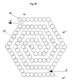
- FIG. 16 shows an example of a spiral arrangement of two tube groups, one tube group being composed of tubes 26 and the two end tubes being designated 26 'and 26 ".
- the end tubes of the other tube groups are designated 26"' and 26 "” .
- These two tube groups can also be put together via plate tube groups, so that there are two spiral plate tube groups. If two spiral plate-tube groups are put together in the manner shown in FIG. 16, a channel results for the medium that is to flow around the tubes in the finished heat and / or material exchanger, into which the medium, for example in the direction of arrow C, on the outer circumference 1 flows, then to the middle and then to the outside and flows out again in the circumferential direction in the direction of arrow D.
- the medium changes the direction of rotation once, which increases the effectiveness of such a heat exchanger.
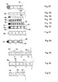
- FIGS. 17 to 27 the internal structure of tube plates is shown as an example, in sections and schematically in cross section.
- 17 is a plate 27 which has continuous cavities 28 with a circular cross section.
- the lugs 29 on the plate 27 are referred to as turbulence promoters and serve to generate turbulence in the medium flowing around the plate.
- a web plate 30 is shown in FIG. 18, which has continuous cavities 31 with a square cross section and turbulence promoters 32. Since the wall thickness in the tube plate shown in FIG. 18 is relatively small, the turbulence promoters 32 can also act as reinforcing ribs for the plate 30.
- FIG. 19 also shows a multi-wall sheet 33 with thicker walls through which cavities 34 pass. The turbulence promoters are designated 32 'here.
- Figure 20 shows the detail of a tube group, which is composed of two different types of tubes.
- the two types of tubes differ mainly in their different diameters.
- tubes 20 with large and 36 with small diameters alternate.
- the outer edge of this configuration is equipped with a nose 37 made of solid material, which serves as protection against erosion and damage.
- the nose 37 can be produced, for example, by welding a solid wire to the last tube 35.
- several pipes 38 of the same diameter are joined together.
- the plate is designated 41, which has continuous cavities 40 which have an elliptical cross section.
- the plate 41 is reinforced on its outer edge - again as Protection against erosion and damage -.
- the plate 42 has a plurality of continuous circular cavities 43.
- the plate 42 is equipped with a nose 44 (protective nose).
- the plate 45 again has continuous circular cavities 46.
- FIG. 25 shows a multi-wall sheet 47 with a protective nose 48.
- a multi-wall sheet is also shown in FIG.
- the last web is cut open on the outer edge of the plate and a solid wire 52 is inserted into the cut web as a protective lug.
- FIG. 31 shows three tubes 59 which are twisted together and which likewise form a tube group. Similar arrangements can also be made by weaving tubes as “shot tubes”.
- FIGS. 32 and 33 schematically show how tube plates can be arranged in inserts.
- the insert is designated 60, in which tube plates 61 are inserted next to one another.
- the thermoplastic material injected by the method according to the invention, which connects the tubes to the insert, is designated by 62.
- the plates 64 are arranged one behind the other and connected to the insert 63 via the thermoplastic material 65.
- Figures 34 and 35 show two embodiments of inserts 66 and 68 in perspective, in which through openings 67 and 69 are arranged for receiving tube plates.
- FIG. 36 shows a device according to the invention for producing plate-to-material and / or plate heat exchangers.
- An insert 70 which also serves as a positioning element for the tube plates, is inserted into the upper mold 71, which is positioned on the lower mold 72.
- the lower mold 72 has continuous cavities 73 which are provided for the passage of a cooling or heating medium.
- Injection channels 74 are also incorporated into the lower mold 72.
- a T-shaped recess 75 is milled into the lower mold 72; it serves to hold the lower mold 72 in the frame of the injection molding machine.
- Mandrels 79 are inserted into the lower mold 72 in a non-positive and positive manner.
- a tube plate 77 is positioned in the insert 70, each continuous cavity 78 of the tube plate 77 including a mandrel 79.
- the continuous cavities 78 of the tube plate 77 and the mandrels 79 are only shown in the schematic illustration according to FIG. 36 in the left half of the figure.
- the cavity to be filled with thermoplastic material by injection molding, which is formed by the lower mold 72, the tube plate 77, the insert 70 and optionally the mandrels 79, is denoted by 76 in FIG.
- the procedure for carrying out the method according to the invention is as follows: the insert 70 and the upper mold 71 are placed on the lower mold 72 fastened in the injection molding machine. A tube plate 77 is then inserted into each through opening of the insert 70 such that a mandrel 79 is positioned in each through cavity 78 of the tube plate 77. After all tube plates 77 have been positioned, they are fixed against axial displacement using known means. After the lower mold 72 and thus also the mandrels 79 have been heated to a temperature T c , a thermoplastic polymer can be injected under pressure via the injection channel 74. Towards the end of the injection process, the lower mold 72 and thus also the mandrels 79 are cooled.
- the upper mold 71 which is formed in two parts for this purpose, is removed, after which the insert 70 with the tube plates 77 connected to it is removed can be. Then a new insert 70 and the upper mold 71 are again positioned on the lower mold 72. The free ends of the tube plates 77 can now be inserted together into the openings of the second insert 70.
- FIG. 37 shows another device according to the invention for producing plate-to-material and / or plate heat exchangers.
- the insert is designated by 80, the upper mold by 81 and the lower mold by 82.
- the lower mold 82 in which a T-shaped recess 85 is incorporated for receiving in the injection molding machine, mandrels 89 are inserted in a non-positive and positive manner, the mandrels 89 each having a continuous cavity 90. All continuous cavities 90 of the mandrels 89 are connected to a distributor 91, by means of which cooling or heating medium can be supplied or extracted via the continuous cavities 90 of the mandrels 89.
- the lower mold 82 itself likewise has a heating or cooling device 83.
- a plate 87 with continuous cavities 88 is positioned in the insert 80. Again, the continuous cavities 88 of the plate 87 and the mandrels 89 are only shown in the left half of the figure.
- FIG. 38 shows schematically a tube plate heat exchanger, produced by the method according to the invention and provided with two tube connections.
- the tube group plates 94 are connected at both ends via the injection molding material 93 to an insert 92, to each of which a half tube 95 is welded.
- the foremost tube plate 94 ' is cut open in the schematic, perspective illustration according to FIG. 39 in order to make it clear that these tube plates 94 each have a larger number of continuous cavities, as can be seen from the breaking edge of the tube plate 94'.
- the detail X which in Figure 39 is shown, the structure of the tube plate 94 'is still clarified, with the section of the tube plate with 94 "and the continuous cavities with 96.
- the tubular plate heat exchanger shown in perspective in FIG. 38 which was produced by the method according to the invention, is particularly suitable for heating or cooling gaseous media, for example air.
- a cooling or heating medium can be passed in the direction of the arrow E in the direction of the arrow E, which then passes through the continuous cavities 96 of the tube group plates 94 in the bottom tube arrives and flows out of it in the direction of arrow F.
- a gas stream which is blown through the plates in the direction of arrow G can be heated or cooled.
- the medium which flows in in the direction of the arrow E and flows out in the direction of the arrow F can be cooled or heated by the gas stream (direction of the arrow G).
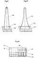
- FIG. 40 schematically shows the structure of an insert 97 with a circumferential groove 98 on the inside and a circumferential groove 99 on the outside of the insert 97.
- Such an insert 97 can, for example, be inserted into an injection mold according to FIG.
- the insert 97 is shown in section on the right half of the picture and in plan view on the left half of the picture.
- the continuous cavities are shown in section and labeled 100. In the top view, the position of further continuous cavities was noted with dash-dotted lines 101.
- the circumferential groove 98 on the inside of the insert 97 ensures reliable protection against axial displacement of the thermoplastic material after injection molding and curing.
- the outer circumferential groove 99 serves on the one hand to secure the insert 97 in the injection mold against axial displacement, and on the other hand this groove can be used for sealing purposes if, for example, the insert connected to the pipes is inserted into a housing.
- FIG. 41 shows a mandrel 102, the free end of which is conical.
- the tip of the free end is blunted and shown here in a hemisphere.
- the other end 103 of the mandrel 102 is cylindrical and embedded in the bottom 104 of an injection mold, which is only shown in part.
- FIG. 42 shows a mandrel 105, the cross section of which also decreases towards the free end.
- the outer contour can be viewed as a parabola curve.
- the mandrel 105 is embedded with its cylindrical end in a bottom 107 shown in sections. Since after the injection molding process the inside of the tubes and / or the thermoplastic material take on the shape of the mandrels, it is easy to see that the design of the mandrel 105, as shown in FIG. 42, is always favorable when the finished material and / or heat exchangers should prevail particularly favorable flow conditions.
- the rear end 108 of the mandrels 109 can have a square cross section, so that several identical mandrels can be placed next to one another, which can then be embedded together in the bottom of an injection mold.
- Such an arrangement is shown with six mandrels 109 in FIG. 43.
- Other cross sections for example hexagonal or rectangular cross sections, are also suitable for the rear end of the mandrels 109. In this way, the inflow channels into the pipes can be shaped in a fluidically favorable manner.
- 1 shows a device according to the invention for producing tube sheets in the assembled state.
- 1 denotes the upper shape and 2 the lower shape.
- a cylindrical insert 3 is inserted into the lower mold 2, the bottom of which has a through opening 10 for each tube, only one through opening being shown in the schematic illustration of the figure.
- a porous polypropylene tube with the dimensions 5.5 / 8.6 mm 0 is inserted up to the upper edge of the cylindrical insert 3. It is advantageous here if the through openings of the cylindrical insert of the lower mold have a clearance fit in relation to the outside diameter of the tubes which are inserted into the through openings of the cylindrical insert before the injection molding process.
- the term clearance fit is defined in DIN 7182, sheet 2.
- a tube, item 8 is shown in section in the area of the cylindrical insert and uncut in the lower area of the lower mold 2. Further tubes 8 are, as indicated for example in the figure, along the dash-dotted lines 11.
- the upper mold 1 consists of a holder 4, material no. 1.2419, in which the coolant distributor 5, material no. 1.2419 and a mandrel holder 6, material no. 1.2419.
- the holder 4, coolant distributor 5 and mandrel holder 6 can be connected to one another, for example, by screws, which are arranged in a place which is indicated by a dash-dotted line 13.
- mandrels 7 material HWS, are inserted, which have a continuous bore of 2 mm in diameter.
- material HWS are inserted, which have a continuous bore of 2 mm in diameter.
- mandrel 7 is shown, wherein, for example, further mandrels 7 can be arranged along the dash-dotted lines 11.
- the free end of the mandrel 7 is truncated pyramid (15 °).
- the length of the mandrels is set so that the free end of the Mandrel 15 mm protrudes into the opening of the insert 3, so that the length of the mandrel protruding from the upper shape is greater than the thickness of the tube sheet to be produced.
- the thickness of the polypropylene tube sheet is 0.2-D in the example described.
- the insert 3 has a groove 9 of 44 mm width, 2 mm depth on the outer surface, into which the lower mold 2 engages in order to achieve an axial fixation of the insert 3.
- the lower mold 2 is constructed in two parts (not shown in the figure).
- an injection channel 12 is incorporated, through which the melted polypropylene material for producing the tube sheet in the direction of arrow A into the interior 15 formed by the insert 3, the mandrel holder 6 (upper mold) and the tubes 8 under a pressure of 40 bar, is pressed at a temperature of 235 ° C. A sustained pressure of 15 bar is required until the injected polypropylene material cools below the melting point temperature.
- the plasticized polypropylene material is filled with 30% glass fibers to reduce the shrinkage behavior.
- the melt index of the polypropylene used is (according to MFI 230-5) 9 g / 10 min, the crystallite melting temperature 160-166 ° C, the melting point 230-240 ° C.
- Bores 13 are provided in the holder 4 of the upper mold 1, and bores 14 are provided in the lower mold 2, through which cooling or heating means can be passed for tempering the injection mold.
- the casting mold is brought to a working temperature of 70 ° C. through the channels 13 and 14 using the liquid heating medium. This temperature is kept constant throughout the injection molding process.
- the divided injection mold is moved apart and the insert 3 provided with a tube plate is removed from the mold.
- An injection mold made of chrome steel consists of an upper and a lower mold, which together form a rectangular cuboid that is 200 mm long, 150 mm wide and 50 mm high.
- the height of the lower mold is 30 mm, the height of the upper mold 20 mm.
- a roughly rectangular recess is also worked into the lower mold, which is 5 mm deep and the upper edges of which are 50 mm from the outer edges of the lower mold.
- 20 mandrels are embedded in 28 rows. Each row is arranged parallel to the short side of the depression. The center distance between adjacent rows is 3.4 mm, the center distance between adjacent mandrels within a row is 2 mm. The rows and mandrels within each row are centered with respect to the outer edges of the recess.
- Each mandrel is 30 mm long and originally had a cylindrical shape with an outer diameter of 1.7 mm.
- the front and back of these mandrels have been flattened to a thickness of 1.2 mm, the flattened surfaces being arranged parallel to the rows.
- the top 3 mm of the mandrels, which are furthest from the bottom of the recess, are tapered.
- slots in the upper mold with a center distance of 3.4 mm.
- the length of each slot is 95 mm, the width 1.5 mm.
- the slots are arranged in such a way that they go through from one side to a distance of 55 mm from the other side, so that the upper shape looks like a kind of comb.
- a side block which also has the shape of a comb, with 28 teeth, which have a center distance of 3.4 mm from one another, is laterally inserted and fixed into the upper mold in such a way that the teeth of the side block are arranged in the slots in the upper mold are.
- each tooth of the side block is 1.45 mm, the length 55 mm and the height 20 mm, so that when the side block is put together with the upper mold, slot-shaped, continuous openings of 40 mm in length remain open, in which when the upper mold is placed on the Underform the tips of the mandrels are positioned.
- Pipe plates made of polyvinylidene fluoride with an outer width of 39.9 mm and an outer thickness of 1.4 mm in which 20 through openings (channels) with a rectangular cross-section with rounded corners (greatest length 1.75 mm, greatest width 1.25 mm, Rounding: r 0.2 mm) are now placed on the mandrels in a row so that the tube plates hit the bottom of the recess worked into the lower mold.
- melt index takes the value 5.5 at 235 ° C. and the value 10.0 at 270 ° C. -
- the last-mentioned temperature is important for example 7 -) injected as a melt, the melt having a temperature of 235 ° C. when flowing into the depression.
- the tube sheet which has now formed, with the tube plates connected to this tube sheet, is removed from the injection mold.
- This tube sheet made of melt is about 4% smaller in volume than the volume of the depression in the lower mold. Because of this volume shrinkage when the melt solidifies, the tube plates are clamped in the tube plate in such a way that the surface of the tube plates has a corrugated or wrinkled surface at the point at which the tube plates emerge from the tube plate.
- the internal pressure, at which the partitions of the (not yet cast) tube plates normally burst within 60 seconds, is around 28 bar at 20 ° C. If the tube plates are cast in the manner described, the partitions burst at a pressure of 6 bar within 60 seconds.
- Example 2 The procedure is as in Example 2. Only the temperature of the injection mold and thus the temperature of the tube plates is increased to 65 ° C with the help of a heating medium (oil) before the PFDF (polyvinylidene fluoride) melt is injected into the recess. For this purpose, the heating medium is pumped through channels provided in the injection mold.
- PFDF polyvinylidene fluoride
- the tube plates are again corrugated or wrinkled at the point of exit from the tube sheet.
- the pressure at which the tube plates burst within 60 seconds is again about 6 bar.
- a recess 3 mm deep, 102 mm long and 52 mm wide is worked into the upper mold according to Example 2, into which the side block has already been inserted and fastened.
- An insert made of PDVF is placed in this recess, the insert being 3 mm thick, 101 mm long and 51 mm wide.
- the insert has 28 slots which are congruent with respect to the slots formed by the upper mold and the side block and are aligned after the insertion.
- the injection mold After the injection mold has been assembled with the insert and the tube plates have been attached in the manner described in Example 1, the injection mold is heated to 25 ° C. and then melted from PVDF at a temperature of 235 ° C. is injected into the depression of the lower mold until a Pressure of 30 bar is reached. Now the injection mold is cooled to 160 ° C at this pressure. After complete cooling, the insert, which is now connected to the tube plates via the injection molding material, is removed from the injection mold.
- the volume shrinkage of the tube sheet is now only 2.3% with respect to the volume of the depression of the lower mold.
- the tube plates have no corrugations or folds at any point, and the pressure at which the tube plates burst within 60 seconds is now about 28 bar.
- Example 4 is repeated, but the temperature of the injection mold, and thus the temperature of the use of the tube sheets, is set to 65 ° C. before the injection molding material is injected.
- Example 4 is repeated, but the temperature of the injection mold is set to 110 ° C., while the temperature of the insert and the tube plates has been increased in a separate oven to such an extent that they then still have a temperature of 145 ° after installation in the injection mold C when the injection molding material is injected.
- the pressure with which the material is injected is reduced from 30 bar to 15 bar, but is increased to 40 bar after 15 seconds and left at this pressure for 15 seconds, after which the pressure is reduced to 0 bar.
- This method makes it possible to refill the injection molding material into the injection mold after cooling, thereby compensating for the shrinkage of the material introduced first.
- Example 5 The conditions of Example 5 are observed, but the injection temperature of the PVDF melt is increased to 270 ° C. When the melt is injected, melt emerges from the slots in the upper mold (between the slot wall and the outer wall of the tube plates) at the pressure of 30 bar to be achieved.
- the product produced by this process again has a burst pressure of 28 bar.
- the tube plates can be pulled in one go force of about 1000 N cannot be pulled out of the tube sheet. With a tensile force application of 1000 N, a sinking (elongation) can be observed for some tube plates in the area of the melt exit point. Such an amount of polymer leaked out from these plates that it came into contact with the tube plates in an area where the tube plates were no longer supported by the mandrels, causing the tube plates to be severely deformed and partially having bubbles in the walls .
- Example 4 is repeated, but the temperature of the injection mold and the temperature of the use of the tube sheets are set to 80 ° C. before the injection molding material, to which 20% phlogopite (mica) has been added, is injected evenly.
- the largest dimension of the mica plates was 300 10-6 m.
Landscapes
- Engineering & Computer Science (AREA)
- Manufacturing & Machinery (AREA)
- Mechanical Engineering (AREA)
- Chemical & Material Sciences (AREA)
- Chemical Kinetics & Catalysis (AREA)
- Physics & Mathematics (AREA)
- Thermal Sciences (AREA)
- General Engineering & Computer Science (AREA)
- Injection Moulding Of Plastics Or The Like (AREA)
- Moulds For Moulding Plastics Or The Like (AREA)
- Heat-Exchange Devices With Radiators And Conduit Assemblies (AREA)
Claims (40)
Applications Claiming Priority (4)
| Application Number | Priority Date | Filing Date | Title |
|---|---|---|---|
| DE19843426445 DE3426445A1 (de) | 1984-07-18 | 1984-07-18 | Vorrichtung und verfahren zum herstellen von rohrboeden fuer waerme und/oder stoffaustauscher |
| DE3426445 | 1984-07-18 | ||
| DE3446293 | 1984-12-19 | ||
| DE3446293 | 1984-12-19 |
Publications (3)
| Publication Number | Publication Date |
|---|---|
| EP0168558A2 EP0168558A2 (fr) | 1986-01-22 |
| EP0168558A3 EP0168558A3 (en) | 1988-03-02 |
| EP0168558B1 true EP0168558B1 (fr) | 1990-01-31 |
Family
ID=25823053
Family Applications (1)
| Application Number | Title | Priority Date | Filing Date |
|---|---|---|---|
| EP85104437A Expired - Lifetime EP0168558B1 (fr) | 1984-07-18 | 1985-04-12 | Procédé et dispositif pour la fabrication d'échangeurs de chaleur et/ou de matière comportant des tuyaux |
Country Status (3)
| Country | Link |
|---|---|
| US (1) | US4740344A (fr) |
| EP (1) | EP0168558B1 (fr) |
| DE (1) | DE3575695D1 (fr) |
Families Citing this family (26)
| Publication number | Priority date | Publication date | Assignee | Title |
|---|---|---|---|---|
| US5294397A (en) * | 1987-06-28 | 1994-03-15 | Terumo Kabushiki Kaisha | Heat exchanger for medical treatment |
| DE3806517A1 (de) * | 1988-03-01 | 1989-09-14 | Akzo Gmbh | Rohrboden fuer waerme- und/oder stoffaustauscher, dessen verwendung sowie verfahren zu dessen herstellung |
| DE3809557A1 (de) * | 1988-03-22 | 1989-10-12 | Akzo Gmbh | Stoff- und/oder waermetauscher |
| US4996923A (en) * | 1988-04-07 | 1991-03-05 | Olin Corporation | Matrix-supported flechette load and method and apparatus for manufacturing the load |
| US4935177A (en) * | 1988-04-07 | 1990-06-19 | Olin Corporation | Method of and apparatus for making a flechette load |
| DE3813882A1 (de) * | 1988-04-25 | 1989-11-09 | Gen Electric Plastics Bv | Verfahren zum anbringen eines flansches an einen waermetauscherkoerper aus thermoplastischem kunststoff |
| JPH07171356A (ja) * | 1993-12-17 | 1995-07-11 | Kitz Corp | 中空糸膜集束体及びその製造方法 |
| DE4412756C2 (de) * | 1994-04-13 | 1996-06-20 | Gore W L & Ass Gmbh | Schlaucheinheit und Verfahren zur Herstellung derselben |
| DE69713278T2 (de) * | 1996-02-07 | 2003-02-06 | Anthony Joseph Cesaroni | Verbinden von rohren aus thermoplastischen polymeren |
| US5743011A (en) * | 1996-02-23 | 1998-04-28 | Mascotech Tubular Products, Inc. | Process of manufacturing vehicle manifolds |
| US6364008B1 (en) | 1999-01-22 | 2002-04-02 | E. I. Du Pont De Nemours And Company | Heat exchanger with tube plates |
| WO2000079199A1 (fr) * | 1999-06-22 | 2000-12-28 | Dupont Canada Inc. | Echangeurs thermiques formes de tubes lies thermiquement |
| WO2000079206A1 (fr) * | 1999-06-22 | 2000-12-28 | Dupont Canada Inc. | Echangeur de chaleur forme a partir de tubes par extrusion et collage thermique simultanes |
| WO2000079198A1 (fr) * | 1999-06-22 | 2000-12-28 | Dupont Canada Inc. | Echangeur thermique forme de tubes assembles par collage au solvant |
| EP1390681A4 (fr) * | 2001-05-02 | 2007-12-26 | Aquatherm Ind Inc | Insert de surmoulage pour echangeur de chaleur |
| US6904963B2 (en) * | 2003-06-25 | 2005-06-14 | Valeo, Inc. | Heat exchanger |
| FR2862747B1 (fr) * | 2003-11-20 | 2008-09-05 | Commissariat Energie Atomique | Plaque d'echangeur de chaleur, et cet echangeur |
| US6997248B2 (en) * | 2004-05-19 | 2006-02-14 | Outokumpu Oyj | High pressure high temperature charge air cooler |
| DE102005039555A1 (de) * | 2005-08-22 | 2007-03-01 | Abb Technology Ltd. | Verfahren zur Herstellung von Schalterpolteilen für Nieder - Mittel - und Hochspannungsschaltanlagen, sowie Schalterpolteil selbst |
| ES2718251T3 (es) | 2006-04-25 | 2019-06-28 | Zenon Tech Partnership | Elemento soporte para módulo de membranas con fibras huecas |
| CN102744879B (zh) * | 2012-07-20 | 2014-08-27 | 株洲宏大高分子材料有限公司 | 一种氟塑料换热器的薄壁微管的焊接方法及装置 |
| US9227353B2 (en) * | 2012-11-08 | 2016-01-05 | Solar Hydronics Corporation | Molding apparatus and method for operating same |
| DE102013206203A1 (de) * | 2013-04-09 | 2014-10-09 | BSH Bosch und Siemens Hausgeräte GmbH | Kältegerät mit einem Verdampfer |
| DE102014010618B4 (de) * | 2014-07-21 | 2026-03-26 | Zf Airbag Germany Gmbh | Berstvorrichtung für einen Hybridgasgenerator |
| KR20190104449A (ko) * | 2014-12-24 | 2019-09-09 | 디아이씨 가부시끼가이샤 | 중공사 탈기 모듈 및 잉크젯 프린터 |
| JP7451856B2 (ja) * | 2019-08-27 | 2024-03-19 | 三桜工業株式会社 | 固定部材付き樹脂管の製造方法及び固定部材付き樹脂管の製造装置 |
Family Cites Families (19)
| Publication number | Priority date | Publication date | Assignee | Title |
|---|---|---|---|---|
| GB731431A (en) * | 1951-03-06 | 1955-06-08 | Ustav Pro Vyzkum Motorovych Vo | A radiator, particularly for internal-combustion engines, and a method of its manufacture |
| US3471178A (en) * | 1966-05-18 | 1969-10-07 | Saline Water Conversion Corp | Tube sheet connector having flexible adhesive sealing means |
| GB1214841A (en) * | 1967-02-20 | 1970-12-02 | Atomic Energy Authority Uk | Joining plastic materials |
| DE1926187A1 (de) * | 1969-05-22 | 1970-11-26 | Schoell Dr Ing Guenter | Waermeaustauschelement aus Werkstoffen mit geringer Waermeleitfaehigkeit und Festigkeit |
| DE2028710A1 (de) * | 1970-06-11 | 1971-12-16 | Kessler & Co Tech Chem Gmbh | Verfahren zur Montage einer Schlauch-Endarmatur |
| GB1379511A (en) * | 1970-10-01 | 1975-01-02 | Serck Industries Ltd | Manufacture of tubular heat exchangers |
| DE2051593A1 (de) * | 1970-10-21 | 1972-04-27 | Hoehne, Bruno, 6901 Bammental | Regal, welches aus Winkelstücken zusammengesetzt ist, vornehmlich aus Kunststoff hergestellt |
| DE2204167A1 (de) * | 1972-01-29 | 1973-08-09 | Krupp Gmbh | Waermetauscher und verfahren zu seiner herstellung |
| FR2267868A1 (en) * | 1974-04-22 | 1975-11-14 | Rousselin Albert | Cast resin panels traversed by several tubes - for mfr. of e.g. heat exchanger manifolds in one operation |
| FR2369076A1 (fr) * | 1976-11-02 | 1978-05-26 | Chausson Usines Sa | Procede pour |
| US4138460A (en) * | 1977-06-10 | 1979-02-06 | Cordis Dow Corp. | Method for forming tubesheets on hollow fiber tows and forming hollow fiber bundle assemblies containing same |
| DE2728827B2 (de) * | 1977-06-27 | 1979-05-03 | Ford-Werke Ag, 5000 Koeln | Wärmetauscher, insbesondere für Kraftfahrzeuge |
| DE2734958A1 (de) * | 1977-08-03 | 1979-02-15 | Froehlich Air Ag | Verfahren zur herstellung eines rohrwaermetauschers und nach diesem verfahren hergestellter rohrwaermetauscher |
| DE2920259A1 (de) * | 1979-05-18 | 1980-11-27 | Manfred Goettlicher | Steckverbinder und verfahren zu dessen herstellung |
| IT1119324B (it) * | 1979-07-04 | 1986-03-10 | Comind Spa | Radiatore perfezionato particolarmente per climatizzatori di autoveicoli |
| IL57898A (en) * | 1979-07-26 | 1983-05-15 | Helioset Advanced Tech | Method for injection-molding of elements onto extruded units |
| JPS5863428A (ja) * | 1981-10-07 | 1983-04-15 | ウセヴオロド・ヴアシリエヴイツチ・アブラモフ | 熱可塑性樹脂の射出成形方法と射出成形用の割り型 |
| DE3142921C2 (de) * | 1981-10-29 | 1984-04-05 | Espo Wierden B.V., 7641 Wierden | Vorrichtung zur Herstellung eines eine Vielzahl von Rohre aufweisenden Tauscherelementes |
| JPS59136213A (ja) * | 1983-01-26 | 1984-08-04 | Fujitsu Kiden Ltd | 樹脂成形金型の冷却方法 |
-
1985
- 1985-04-12 EP EP85104437A patent/EP0168558B1/fr not_active Expired - Lifetime
- 1985-04-12 DE DE8585104437T patent/DE3575695D1/de not_active Expired - Lifetime
- 1985-07-02 US US06/751,121 patent/US4740344A/en not_active Expired - Fee Related
Also Published As
| Publication number | Publication date |
|---|---|
| US4740344A (en) | 1988-04-26 |
| EP0168558A3 (en) | 1988-03-02 |
| DE3575695D1 (de) | 1990-03-08 |
| EP0168558A2 (fr) | 1986-01-22 |
Similar Documents
| Publication | Publication Date | Title |
|---|---|---|
| EP0168558A2 (fr) | Procédé et dispositif pour la fabrication d'échangeurs de chaleur et/ou de matière comportant des tuyaux | |
| EP0226825B1 (fr) | Liaison d'un profilé creux avec une plaque en matière plastique, en particulier pour la fabrication d'échangeurs de chaleur | |
| DE2450818C3 (de) | Verfahren zum Abkühlen der äußeren Oberfläche eines rohrförmigen Stranges vor dessen Blasformung | |
| DE2809386C3 (de) | Vorrichtung zum Kalibrieren und Kühlen von Profilen aus thermoplastischen Kunstststoffen | |
| DE60003163T2 (de) | Rohr aus thermoplastischem kunststoff | |
| DE4026851A1 (de) | Zierleiste aus kunststoff und verfahren und vorrichtung zum herstellen | |
| EP0243574B1 (fr) | Echangeur de chaleur et procédé de fabrication d'échangeurs de chaleur | |
| EP0243575A2 (fr) | Echangeur de chaleur et/ou de matière et procédé de fabrication des échangeurs de chaleur et/ou de matière | |
| EP0299182B1 (fr) | Procédé pour souder des extrémités de tuyaux à un plateau à tubes | |
| DE3543283A1 (de) | Verfahren zum verbinden von hohlprofilkoerpern mit formkoerpern aus thermoplastischem kunststoff | |
| EP3609672B1 (fr) | Connecteur enfichable en matière plastique et procédé de fabrication associé | |
| EP1346814B1 (fr) | Dispositif de calibration | |
| AT412767B (de) | Verfahren zum herstellen von länglichen gegenständen sowie mit diesem verfahren hergestellter gegenstand | |
| EP4214043A1 (fr) | Dispositif de régulation de la température d'un élément et son procédé de fabrication | |
| EP0331023B1 (fr) | Procédé de fabrication d'une plaque d'extrémité pour un échangeur de chaleur et/ou de matière | |
| DE112016002244B4 (de) | Wärmetauscher und Herstellungsverfahren hierfür | |
| DE8611642U1 (de) | Wärmetauscher | |
| DE19961455A1 (de) | Verfahren zum Herstellen eines abgezweigten Rohres, Vorrichtung zum Rohrherstellen und abgezweigtes Rohr | |
| DE19854173C2 (de) | Metallschaumformkörper | |
| DE3828383A1 (de) | Spritzgussform | |
| DE102004030247A1 (de) | Herstellungsverfahren für laserstrahldurchlässiges Bauteil, Harzformvorrichtung und Herstellungsverfahren für Verbundharzprodukt | |
| DE2406952C2 (de) | Vorrichtung zum kontinuierlichen Herstellen einer Profilfolie | |
| DE202005017314U1 (de) | Druckfeste Baugruppe sowie Konnektor für eine derartige Baugruppe | |
| DE3636177A1 (de) | Verfahren, insbesondere zum herstellen eines waermetauschers sowie waermetauscher | |
| DE3426445A1 (de) | Vorrichtung und verfahren zum herstellen von rohrboeden fuer waerme und/oder stoffaustauscher |
Legal Events
| Date | Code | Title | Description |
|---|---|---|---|
| PUAI | Public reference made under article 153(3) epc to a published international application that has entered the european phase |
Free format text: ORIGINAL CODE: 0009012 |
|
| AK | Designated contracting states |
Designated state(s): BE CH DE FR GB IT LI NL SE |
|
| PUAL | Search report despatched |
Free format text: ORIGINAL CODE: 0009013 |
|
| AK | Designated contracting states |
Kind code of ref document: A3 Designated state(s): BE CH DE FR GB IT LI NL SE |
|
| 17P | Request for examination filed |
Effective date: 19880323 |
|
| RAP1 | Party data changed (applicant data changed or rights of an application transferred) |
Owner name: AKZO PATENTE GMBH |
|
| 17Q | First examination report despatched |
Effective date: 19890314 |
|
| RBV | Designated contracting states (corrected) |
Designated state(s): BE CH DE FR GB IT LI NL |
|
| GRAA | (expected) grant |
Free format text: ORIGINAL CODE: 0009210 |
|
| ITF | It: translation for a ep patent filed | ||
| AK | Designated contracting states |
Kind code of ref document: B1 Designated state(s): BE CH DE FR GB IT LI NL |
|
| ET | Fr: translation filed | ||
| GBT | Gb: translation of ep patent filed (gb section 77(6)(a)/1977) | ||
| REF | Corresponds to: |
Ref document number: 3575695 Country of ref document: DE Date of ref document: 19900308 |
|
| PLBE | No opposition filed within time limit |
Free format text: ORIGINAL CODE: 0009261 |
|
| STAA | Information on the status of an ep patent application or granted ep patent |
Free format text: STATUS: NO OPPOSITION FILED WITHIN TIME LIMIT |
|
| 26N | No opposition filed | ||
| PGFP | Annual fee paid to national office [announced via postgrant information from national office to epo] |
Ref country code: FR Payment date: 19930223 Year of fee payment: 9 |
|
| PGFP | Annual fee paid to national office [announced via postgrant information from national office to epo] |
Ref country code: GB Payment date: 19930315 Year of fee payment: 9 Ref country code: DE Payment date: 19930315 Year of fee payment: 9 |
|
| PGFP | Annual fee paid to national office [announced via postgrant information from national office to epo] |
Ref country code: CH Payment date: 19930405 Year of fee payment: 9 |
|
| ITTA | It: last paid annual fee | ||
| PGFP | Annual fee paid to national office [announced via postgrant information from national office to epo] |
Ref country code: NL Payment date: 19930430 Year of fee payment: 9 |
|
| PGFP | Annual fee paid to national office [announced via postgrant information from national office to epo] |
Ref country code: BE Payment date: 19930602 Year of fee payment: 9 |
|
| PG25 | Lapsed in a contracting state [announced via postgrant information from national office to epo] |
Ref country code: GB Effective date: 19940412 |
|
| PG25 | Lapsed in a contracting state [announced via postgrant information from national office to epo] |
Ref country code: LI Effective date: 19940430 Ref country code: CH Effective date: 19940430 Ref country code: BE Effective date: 19940430 |
|
| BERE | Be: lapsed |
Owner name: AKZO PATENTE G.M.B.H. Effective date: 19940430 |
|
| PG25 | Lapsed in a contracting state [announced via postgrant information from national office to epo] |
Ref country code: NL Effective date: 19941101 |
|
| GBPC | Gb: european patent ceased through non-payment of renewal fee |
Effective date: 19940412 |
|
| NLV4 | Nl: lapsed or anulled due to non-payment of the annual fee | ||
| PG25 | Lapsed in a contracting state [announced via postgrant information from national office to epo] |
Ref country code: FR Effective date: 19941229 |
|
| REG | Reference to a national code |
Ref country code: CH Ref legal event code: PL |
|
| PG25 | Lapsed in a contracting state [announced via postgrant information from national office to epo] |
Ref country code: DE Effective date: 19950103 |
|
| REG | Reference to a national code |
Ref country code: FR Ref legal event code: ST |