EP0226825B1 - Liaison d'un profilé creux avec une plaque en matière plastique, en particulier pour la fabrication d'échangeurs de chaleur - Google Patents
Liaison d'un profilé creux avec une plaque en matière plastique, en particulier pour la fabrication d'échangeurs de chaleur Download PDFInfo
- Publication number
- EP0226825B1 EP0226825B1 EP86116060A EP86116060A EP0226825B1 EP 0226825 B1 EP0226825 B1 EP 0226825B1 EP 86116060 A EP86116060 A EP 86116060A EP 86116060 A EP86116060 A EP 86116060A EP 0226825 B1 EP0226825 B1 EP 0226825B1
- Authority
- EP
- European Patent Office
- Prior art keywords
- rod
- support plate
- rods
- heat exchanger
- heat
- Prior art date
- Legal status (The legal status is an assumption and is not a legal conclusion. Google has not performed a legal analysis and makes no representation as to the accuracy of the status listed.)
- Expired - Lifetime
Links
Images




Classifications
-
- B—PERFORMING OPERATIONS; TRANSPORTING
- B29—WORKING OF PLASTICS; WORKING OF SUBSTANCES IN A PLASTIC STATE IN GENERAL
- B29C—SHAPING OR JOINING OF PLASTICS; SHAPING OF MATERIAL IN A PLASTIC STATE, NOT OTHERWISE PROVIDED FOR; AFTER-TREATMENT OF THE SHAPED PRODUCTS, e.g. REPAIRING
- B29C65/00—Joining or sealing of preformed parts, e.g. welding of plastics materials; Apparatus therefor
- B29C65/66—Joining or sealing of preformed parts, e.g. welding of plastics materials; Apparatus therefor by liberation of internal stresses, e.g. shrinking of one of the parts to be joined
-
- B—PERFORMING OPERATIONS; TRANSPORTING
- B29—WORKING OF PLASTICS; WORKING OF SUBSTANCES IN A PLASTIC STATE IN GENERAL
- B29C—SHAPING OR JOINING OF PLASTICS; SHAPING OF MATERIAL IN A PLASTIC STATE, NOT OTHERWISE PROVIDED FOR; AFTER-TREATMENT OF THE SHAPED PRODUCTS, e.g. REPAIRING
- B29C57/00—Shaping of tube ends, e.g. flanging, belling or closing; Apparatus therefor, e.g. collapsible mandrels
-
- B—PERFORMING OPERATIONS; TRANSPORTING
- B29—WORKING OF PLASTICS; WORKING OF SUBSTANCES IN A PLASTIC STATE IN GENERAL
- B29C—SHAPING OR JOINING OF PLASTICS; SHAPING OF MATERIAL IN A PLASTIC STATE, NOT OTHERWISE PROVIDED FOR; AFTER-TREATMENT OF THE SHAPED PRODUCTS, e.g. REPAIRING
- B29C65/00—Joining or sealing of preformed parts, e.g. welding of plastics materials; Apparatus therefor
- B29C65/02—Joining or sealing of preformed parts, e.g. welding of plastics materials; Apparatus therefor by heating, with or without pressure
-
- B—PERFORMING OPERATIONS; TRANSPORTING
- B29—WORKING OF PLASTICS; WORKING OF SUBSTANCES IN A PLASTIC STATE IN GENERAL
- B29C—SHAPING OR JOINING OF PLASTICS; SHAPING OF MATERIAL IN A PLASTIC STATE, NOT OTHERWISE PROVIDED FOR; AFTER-TREATMENT OF THE SHAPED PRODUCTS, e.g. REPAIRING
- B29C65/00—Joining or sealing of preformed parts, e.g. welding of plastics materials; Apparatus therefor
- B29C65/02—Joining or sealing of preformed parts, e.g. welding of plastics materials; Apparatus therefor by heating, with or without pressure
- B29C65/14—Joining or sealing of preformed parts, e.g. welding of plastics materials; Apparatus therefor by heating, with or without pressure using wave energy, i.e. electromagnetic radiation, or particle radiation
- B29C65/1429—Joining or sealing of preformed parts, e.g. welding of plastics materials; Apparatus therefor by heating, with or without pressure using wave energy, i.e. electromagnetic radiation, or particle radiation characterised by the way of heating the interface
- B29C65/1448—Joining or sealing of preformed parts, e.g. welding of plastics materials; Apparatus therefor by heating, with or without pressure using wave energy, i.e. electromagnetic radiation, or particle radiation characterised by the way of heating the interface radiating the edges of the parts to be joined, e.g. for curing a layer of adhesive placed between two flat parts to be joined, e.g. for making CDs or DVDs
-
- B—PERFORMING OPERATIONS; TRANSPORTING
- B29—WORKING OF PLASTICS; WORKING OF SUBSTANCES IN A PLASTIC STATE IN GENERAL
- B29C—SHAPING OR JOINING OF PLASTICS; SHAPING OF MATERIAL IN A PLASTIC STATE, NOT OTHERWISE PROVIDED FOR; AFTER-TREATMENT OF THE SHAPED PRODUCTS, e.g. REPAIRING
- B29C66/00—General aspects of processes or apparatus for joining preformed parts
- B29C66/01—General aspects dealing with the joint area or with the area to be joined
- B29C66/05—Particular design of joint configurations
- B29C66/10—Particular design of joint configurations particular design of the joint cross-sections
- B29C66/12—Joint cross-sections combining only two joint-segments; Tongue and groove joints; Tenon and mortise joints; Stepped joint cross-sections
- B29C66/122—Joint cross-sections combining only two joint-segments, i.e. one of the parts to be joined comprising only two joint-segments in the joint cross-section
- B29C66/1222—Joint cross-sections combining only two joint-segments, i.e. one of the parts to be joined comprising only two joint-segments in the joint cross-section comprising at least a lapped joint-segment
-
- B—PERFORMING OPERATIONS; TRANSPORTING
- B29—WORKING OF PLASTICS; WORKING OF SUBSTANCES IN A PLASTIC STATE IN GENERAL
- B29C—SHAPING OR JOINING OF PLASTICS; SHAPING OF MATERIAL IN A PLASTIC STATE, NOT OTHERWISE PROVIDED FOR; AFTER-TREATMENT OF THE SHAPED PRODUCTS, e.g. REPAIRING
- B29C66/00—General aspects of processes or apparatus for joining preformed parts
- B29C66/01—General aspects dealing with the joint area or with the area to be joined
- B29C66/05—Particular design of joint configurations
- B29C66/10—Particular design of joint configurations particular design of the joint cross-sections
- B29C66/12—Joint cross-sections combining only two joint-segments; Tongue and groove joints; Tenon and mortise joints; Stepped joint cross-sections
- B29C66/122—Joint cross-sections combining only two joint-segments, i.e. one of the parts to be joined comprising only two joint-segments in the joint cross-section
- B29C66/1224—Joint cross-sections combining only two joint-segments, i.e. one of the parts to be joined comprising only two joint-segments in the joint cross-section comprising at least a butt joint-segment
-
- B—PERFORMING OPERATIONS; TRANSPORTING
- B29—WORKING OF PLASTICS; WORKING OF SUBSTANCES IN A PLASTIC STATE IN GENERAL
- B29C—SHAPING OR JOINING OF PLASTICS; SHAPING OF MATERIAL IN A PLASTIC STATE, NOT OTHERWISE PROVIDED FOR; AFTER-TREATMENT OF THE SHAPED PRODUCTS, e.g. REPAIRING
- B29C66/00—General aspects of processes or apparatus for joining preformed parts
- B29C66/50—General aspects of joining tubular articles; General aspects of joining long products, i.e. bars or profiled elements; General aspects of joining single elements to tubular articles, hollow articles or bars; General aspects of joining several hollow-preforms to form hollow or tubular articles
- B29C66/51—Joining tubular articles, profiled elements or bars; Joining single elements to tubular articles, hollow articles or bars; Joining several hollow-preforms to form hollow or tubular articles
- B29C66/53—Joining single elements to tubular articles, hollow articles or bars
- B29C66/534—Joining single elements to open ends of tubular or hollow articles or to the ends of bars
- B29C66/5346—Joining single elements to open ends of tubular or hollow articles or to the ends of bars said single elements being substantially flat
- B29C66/53465—Joining single elements to open ends of tubular or hollow articles or to the ends of bars said single elements being substantially flat said single flat elements being provided with holes facing the tube ends, e.g. for making heat-exchangers
-
- B—PERFORMING OPERATIONS; TRANSPORTING
- B29—WORKING OF PLASTICS; WORKING OF SUBSTANCES IN A PLASTIC STATE IN GENERAL
- B29C—SHAPING OR JOINING OF PLASTICS; SHAPING OF MATERIAL IN A PLASTIC STATE, NOT OTHERWISE PROVIDED FOR; AFTER-TREATMENT OF THE SHAPED PRODUCTS, e.g. REPAIRING
- B29C66/00—General aspects of processes or apparatus for joining preformed parts
- B29C66/70—General aspects of processes or apparatus for joining preformed parts characterised by the composition, physical properties or the structure of the material of the parts to be joined; Joining with non-plastics material
- B29C66/73—General aspects of processes or apparatus for joining preformed parts characterised by the composition, physical properties or the structure of the material of the parts to be joined; Joining with non-plastics material characterised by the intensive physical properties of the material of the parts to be joined, by the optical properties of the material of the parts to be joined, by the extensive physical properties of the parts to be joined, by the state of the material of the parts to be joined or by the material of the parts to be joined being a thermoplastic or a thermoset
- B29C66/739—General aspects of processes or apparatus for joining preformed parts characterised by the composition, physical properties or the structure of the material of the parts to be joined; Joining with non-plastics material characterised by the intensive physical properties of the material of the parts to be joined, by the optical properties of the material of the parts to be joined, by the extensive physical properties of the parts to be joined, by the state of the material of the parts to be joined or by the material of the parts to be joined being a thermoplastic or a thermoset characterised by the material of the parts to be joined being a thermoplastic or a thermoset
- B29C66/7392—General aspects of processes or apparatus for joining preformed parts characterised by the composition, physical properties or the structure of the material of the parts to be joined; Joining with non-plastics material characterised by the intensive physical properties of the material of the parts to be joined, by the optical properties of the material of the parts to be joined, by the extensive physical properties of the parts to be joined, by the state of the material of the parts to be joined or by the material of the parts to be joined being a thermoplastic or a thermoset characterised by the material of the parts to be joined being a thermoplastic or a thermoset characterised by the material of at least one of the parts being a thermoplastic
-
- B—PERFORMING OPERATIONS; TRANSPORTING
- B29—WORKING OF PLASTICS; WORKING OF SUBSTANCES IN A PLASTIC STATE IN GENERAL
- B29C—SHAPING OR JOINING OF PLASTICS; SHAPING OF MATERIAL IN A PLASTIC STATE, NOT OTHERWISE PROVIDED FOR; AFTER-TREATMENT OF THE SHAPED PRODUCTS, e.g. REPAIRING
- B29C66/00—General aspects of processes or apparatus for joining preformed parts
- B29C66/90—Measuring or controlling the joining process
- B29C66/91—Measuring or controlling the joining process by measuring or controlling the temperature, the heat or the thermal flux
- B29C66/914—Measuring or controlling the joining process by measuring or controlling the temperature, the heat or the thermal flux by controlling or regulating the temperature, the heat or the thermal flux
- B29C66/9161—Measuring or controlling the joining process by measuring or controlling the temperature, the heat or the thermal flux by controlling or regulating the temperature, the heat or the thermal flux by controlling or regulating the heat or the thermal flux, i.e. the heat flux
-
- F—MECHANICAL ENGINEERING; LIGHTING; HEATING; WEAPONS; BLASTING
- F28—HEAT EXCHANGE IN GENERAL
- F28F—DETAILS OF HEAT-EXCHANGE AND HEAT-TRANSFER APPARATUS, OF GENERAL APPLICATION
- F28F9/00—Casings; Header boxes; Auxiliary supports for elements; Auxiliary members within casings
- F28F9/02—Header boxes; End plates
- F28F9/04—Arrangements for sealing elements into header boxes or end plates
- F28F9/16—Arrangements for sealing elements into header boxes or end plates by permanent joints, e.g. by rolling
- F28F9/18—Arrangements for sealing elements into header boxes or end plates by permanent joints, e.g. by rolling by welding
- F28F9/187—Arrangements for sealing elements into header boxes or end plates by permanent joints, e.g. by rolling by welding at least one of the parts being non-metallic, e.g. heat-sealing plastic elements
-
- B—PERFORMING OPERATIONS; TRANSPORTING
- B29—WORKING OF PLASTICS; WORKING OF SUBSTANCES IN A PLASTIC STATE IN GENERAL
- B29C—SHAPING OR JOINING OF PLASTICS; SHAPING OF MATERIAL IN A PLASTIC STATE, NOT OTHERWISE PROVIDED FOR; AFTER-TREATMENT OF THE SHAPED PRODUCTS, e.g. REPAIRING
- B29C66/00—General aspects of processes or apparatus for joining preformed parts
- B29C66/70—General aspects of processes or apparatus for joining preformed parts characterised by the composition, physical properties or the structure of the material of the parts to be joined; Joining with non-plastics material
- B29C66/71—General aspects of processes or apparatus for joining preformed parts characterised by the composition, physical properties or the structure of the material of the parts to be joined; Joining with non-plastics material characterised by the composition of the plastics material of the parts to be joined
-
- B—PERFORMING OPERATIONS; TRANSPORTING
- B29—WORKING OF PLASTICS; WORKING OF SUBSTANCES IN A PLASTIC STATE IN GENERAL
- B29C—SHAPING OR JOINING OF PLASTICS; SHAPING OF MATERIAL IN A PLASTIC STATE, NOT OTHERWISE PROVIDED FOR; AFTER-TREATMENT OF THE SHAPED PRODUCTS, e.g. REPAIRING
- B29C66/00—General aspects of processes or apparatus for joining preformed parts
- B29C66/70—General aspects of processes or apparatus for joining preformed parts characterised by the composition, physical properties or the structure of the material of the parts to be joined; Joining with non-plastics material
- B29C66/73—General aspects of processes or apparatus for joining preformed parts characterised by the composition, physical properties or the structure of the material of the parts to be joined; Joining with non-plastics material characterised by the intensive physical properties of the material of the parts to be joined, by the optical properties of the material of the parts to be joined, by the extensive physical properties of the parts to be joined, by the state of the material of the parts to be joined or by the material of the parts to be joined being a thermoplastic or a thermoset
- B29C66/739—General aspects of processes or apparatus for joining preformed parts characterised by the composition, physical properties or the structure of the material of the parts to be joined; Joining with non-plastics material characterised by the intensive physical properties of the material of the parts to be joined, by the optical properties of the material of the parts to be joined, by the extensive physical properties of the parts to be joined, by the state of the material of the parts to be joined or by the material of the parts to be joined being a thermoplastic or a thermoset characterised by the material of the parts to be joined being a thermoplastic or a thermoset
- B29C66/7392—General aspects of processes or apparatus for joining preformed parts characterised by the composition, physical properties or the structure of the material of the parts to be joined; Joining with non-plastics material characterised by the intensive physical properties of the material of the parts to be joined, by the optical properties of the material of the parts to be joined, by the extensive physical properties of the parts to be joined, by the state of the material of the parts to be joined or by the material of the parts to be joined being a thermoplastic or a thermoset characterised by the material of the parts to be joined being a thermoplastic or a thermoset characterised by the material of at least one of the parts being a thermoplastic
- B29C66/73921—General aspects of processes or apparatus for joining preformed parts characterised by the composition, physical properties or the structure of the material of the parts to be joined; Joining with non-plastics material characterised by the intensive physical properties of the material of the parts to be joined, by the optical properties of the material of the parts to be joined, by the extensive physical properties of the parts to be joined, by the state of the material of the parts to be joined or by the material of the parts to be joined being a thermoplastic or a thermoset characterised by the material of the parts to be joined being a thermoplastic or a thermoset characterised by the material of at least one of the parts being a thermoplastic characterised by the materials of both parts being thermoplastics
-
- B—PERFORMING OPERATIONS; TRANSPORTING
- B29—WORKING OF PLASTICS; WORKING OF SUBSTANCES IN A PLASTIC STATE IN GENERAL
- B29C—SHAPING OR JOINING OF PLASTICS; SHAPING OF MATERIAL IN A PLASTIC STATE, NOT OTHERWISE PROVIDED FOR; AFTER-TREATMENT OF THE SHAPED PRODUCTS, e.g. REPAIRING
- B29C66/00—General aspects of processes or apparatus for joining preformed parts
- B29C66/90—Measuring or controlling the joining process
- B29C66/91—Measuring or controlling the joining process by measuring or controlling the temperature, the heat or the thermal flux
- B29C66/914—Measuring or controlling the joining process by measuring or controlling the temperature, the heat or the thermal flux by controlling or regulating the temperature, the heat or the thermal flux
- B29C66/9141—Measuring or controlling the joining process by measuring or controlling the temperature, the heat or the thermal flux by controlling or regulating the temperature, the heat or the thermal flux by controlling or regulating the temperature
- B29C66/91421—Measuring or controlling the joining process by measuring or controlling the temperature, the heat or the thermal flux by controlling or regulating the temperature, the heat or the thermal flux by controlling or regulating the temperature of the joining tools
-
- B—PERFORMING OPERATIONS; TRANSPORTING
- B29—WORKING OF PLASTICS; WORKING OF SUBSTANCES IN A PLASTIC STATE IN GENERAL
- B29C—SHAPING OR JOINING OF PLASTICS; SHAPING OF MATERIAL IN A PLASTIC STATE, NOT OTHERWISE PROVIDED FOR; AFTER-TREATMENT OF THE SHAPED PRODUCTS, e.g. REPAIRING
- B29C66/00—General aspects of processes or apparatus for joining preformed parts
- B29C66/90—Measuring or controlling the joining process
- B29C66/91—Measuring or controlling the joining process by measuring or controlling the temperature, the heat or the thermal flux
- B29C66/919—Measuring or controlling the joining process by measuring or controlling the temperature, the heat or the thermal flux characterised by specific temperature, heat or thermal flux values or ranges
-
- B—PERFORMING OPERATIONS; TRANSPORTING
- B29—WORKING OF PLASTICS; WORKING OF SUBSTANCES IN A PLASTIC STATE IN GENERAL
- B29C—SHAPING OR JOINING OF PLASTICS; SHAPING OF MATERIAL IN A PLASTIC STATE, NOT OTHERWISE PROVIDED FOR; AFTER-TREATMENT OF THE SHAPED PRODUCTS, e.g. REPAIRING
- B29C66/00—General aspects of processes or apparatus for joining preformed parts
- B29C66/90—Measuring or controlling the joining process
- B29C66/94—Measuring or controlling the joining process by measuring or controlling the time
- B29C66/949—Measuring or controlling the joining process by measuring or controlling the time characterised by specific time values or ranges
-
- B—PERFORMING OPERATIONS; TRANSPORTING
- B29—WORKING OF PLASTICS; WORKING OF SUBSTANCES IN A PLASTIC STATE IN GENERAL
- B29L—INDEXING SCHEME ASSOCIATED WITH SUBCLASS B29C, RELATING TO PARTICULAR ARTICLES
- B29L2031/00—Other particular articles
- B29L2031/18—Heat-exchangers or parts thereof
-
- Y—GENERAL TAGGING OF NEW TECHNOLOGICAL DEVELOPMENTS; GENERAL TAGGING OF CROSS-SECTIONAL TECHNOLOGIES SPANNING OVER SEVERAL SECTIONS OF THE IPC; TECHNICAL SUBJECTS COVERED BY FORMER USPC CROSS-REFERENCE ART COLLECTIONS [XRACs] AND DIGESTS
- Y10—TECHNICAL SUBJECTS COVERED BY FORMER USPC
- Y10S—TECHNICAL SUBJECTS COVERED BY FORMER USPC CROSS-REFERENCE ART COLLECTIONS [XRACs] AND DIGESTS
- Y10S165/00—Heat exchange
- Y10S165/454—Heat exchange having side-by-side conduits structure or conduit section
- Y10S165/492—Plural conduits with ends connected to tube plate
- Y10S165/493—Welded or fused joint between conduit end and plate
-
- Y—GENERAL TAGGING OF NEW TECHNOLOGICAL DEVELOPMENTS; GENERAL TAGGING OF CROSS-SECTIONAL TECHNOLOGIES SPANNING OVER SEVERAL SECTIONS OF THE IPC; TECHNICAL SUBJECTS COVERED BY FORMER USPC CROSS-REFERENCE ART COLLECTIONS [XRACs] AND DIGESTS
- Y10—TECHNICAL SUBJECTS COVERED BY FORMER USPC
- Y10S—TECHNICAL SUBJECTS COVERED BY FORMER USPC CROSS-REFERENCE ART COLLECTIONS [XRACs] AND DIGESTS
- Y10S165/00—Heat exchange
- Y10S165/905—Materials of manufacture
-
- Y—GENERAL TAGGING OF NEW TECHNOLOGICAL DEVELOPMENTS; GENERAL TAGGING OF CROSS-SECTIONAL TECHNOLOGIES SPANNING OVER SEVERAL SECTIONS OF THE IPC; TECHNICAL SUBJECTS COVERED BY FORMER USPC CROSS-REFERENCE ART COLLECTIONS [XRACs] AND DIGESTS
- Y10—TECHNICAL SUBJECTS COVERED BY FORMER USPC
- Y10T—TECHNICAL SUBJECTS COVERED BY FORMER US CLASSIFICATION
- Y10T156/00—Adhesive bonding and miscellaneous chemical manufacture
- Y10T156/10—Methods of surface bonding and/or assembly therefor
- Y10T156/1002—Methods of surface bonding and/or assembly therefor with permanent bending or reshaping or surface deformation of self sustaining lamina
- Y10T156/1005—Methods of surface bonding and/or assembly therefor with permanent bending or reshaping or surface deformation of self sustaining lamina by inward collapsing of portion of hollow body
Definitions
- the invention relates to a method for permanently fastening the end (s) of at least one rod made of thermoplastic, each having at least one continuous cavity, in at least one opening of a support plate comprising at least one rod, in which each rod for its fastening in the intended for it Opening of the support plate is positioned, then the rod ends are heated, at least partially softened, expanded and glued to the support plate, each rod cavity having a hydraulic diameter that corresponds to at least 10% of the thinnest wall thickness of the rod, the rod walls can have pores that are maximal Fill 20% of the wall volume, and the support plate consists of thermoplastic at least in the area of the openings, in particular for the production of heat exchangers.
- the invention also relates to a heat exchanger consisting of a number of thermoplastic rods each having at least one continuous cavity, the ends of which are permanently connected to at least one support plate, the cavities widening towards the end of the thermoplastic rods.
- a generic method and a generic heat exchanger is known from DE-OS 33 38 157.
- the tubes are inserted into a tube plate designed as a perforated plate.
- the tube ends are then welded to the tube sheet using an ultrasound head.
- the production of a sonotrode suitable as an ultrasound head is very expensive.
- each tube end has to be welded individually to the tube sheet, which is very complex, or one needs a sonotrode specially produced for each desired tube arrangement and / or number. If the tube ends are individually welded to the tube sheet, individual, already welded tube ends can also partially come loose due to the heat effect when welding adjacent tube ends.
- the outer contour of the sonotrodes can be selected to be conical.
- each tube end on the tube sheet of the finished heat exchanger has a conical widening towards the end. This expansion favors the supply and discharge of the medium flowing in the heat exchanger.
- These extensions result in a lower pressure drop when the fluid flows into the pipes, which is not always desirable, for example if the heat exchanger produced by these processes is to be used as an evaporator.
- the heat exchanger produced according to the known method has an annular bead-shaped elevation on the end face of the tube sheet at each tube outlet end. In addition, a clear boundary line between tube material and tube sheet material is visible when looking at the front of the tube sheet.
- the object of the present invention is to provide a particularly simple method of the type mentioned at the outset, in particular for producing a heat exchanger, in which no expensive tools are required, which can also be carried out independently of the desired arrangement of the rods. It is a further object of the present invention to provide a particularly inexpensive heat exchanger.
- the support plate material and the rod material should merge seamlessly, that is, there should no longer be a visible boundary between the support plate material and the rod material.
- a heat exchanger is also to be made available which is suitable for use as an evaporator.
- the object of the invention is achieved in a generic method in that the ends of the rods are arranged substantially vertically upwards and the support plate substantially horizontally, that from the top the rod ends without mechanical force and contactless so much heat is supplied that expand the outer walls of the rod ends after softening them so that they lie against the walls of the support plate openings and stick to them, whereby the heat exchanger does not stick to the heat source.
- the support plate must at least in the area of the openings consist of a material with which the rods used can stick when using the method according to the invention.
- the rod ends widen and then lie against the inside of the openings in the support plate and adhere to it as heat is added.
- the heat can be supplied by heat radiation, for example by a heating plate. But it can also be caused by sound waves, light, electromagnetic waves, hot gases, or the like. respectively.
- the thermal treatment can be carried out under vacuum or in a protective gas atmosphere.
- the degree of expansion of the rod ends is influenced most favorably by using rods made of a thermoplastic material which has an average coefficient of linear expansion between 100 -10 6 and 400 10-6 1 / K in the range between room temperature and melting temperature.
- the support plate consists of thermoplastic at least in the area of the openings, and so much heat is supplied to the rod ends that the rod ends fuse with the support plate.
- the insertion of the rods into the openings provided in the support plate is facilitated in that support plates are used whose openings are at least in a cross-sectional dimension larger than the corresponding outer cross-sectional dimension of the rod by an amount that is at least 20% of the wall thickness of the rod. It has also been shown that the strength of the connection point between the rod and the support plate can be influenced particularly favorably in this way.
- the method according to the invention is particularly successful when rods are used which can have a porosity of up to 10% of the wall volume, the hydraulic diameter of each cavity between 0.3 and 15 mm, preferably between 0.5 and 7.5 mm, and the wall thickness at the thinnest point is between 5 and 25% of the hydraulic diameter, preferably between 7.5 and 17.5% of the hydraulic diameter.
- the hydraulic diameter (d h ) is defined as the quotient of the fourfold internal cross-sectional area of a channel of the rod divided by the wetted inner circumference (see also Dubbel, Taschenbuch für Maschinenbau, 13th edition, 1970, page 314, paragraph 4):
- Support plates are preferably used, the opening cross-sectional areas of which are widened at least towards the end face in relation to the outer cross section of the rods or rod groups used.
- the rods should be positioned such that the rod ends at least extend into the extensions of the support plate openings.
- the type of cross-sectional enlargement or enlargement towards the end face of the support plate influences the inner contour of the rod, which is achieved by the heat treatment. If the cross-sectional expansion of the openings of the support plate towards the front side is continuous, the inside cross sections of the bars have a narrowing in the direction of the inside of the bar, the area of which is approximately 10 to 60% of the area of the inside cross section, and which then passes inwards to the inside cross section of the bar. If the cross section of the support plate openings is suddenly expanded towards the end face, the inside of the rod end has no or hardly noticeable narrowing of the inside cross section.
- the durability of the connection point between the rod and the support plate can be influenced favorably in that after the positioning, but before the thermal treatment of the rods, any space that may exist between the outer jacket of the rods and the openings of the support plate is at least partially filled with polymer powder.
- Polymer powder is advantageously used which has a melting temperature which is about 5 to 50 ° C., preferably 20 to 50 ° C. below the melting temperature of the rod material.
- the method according to the invention works particularly well if the support plate, rods and, if applicable, that Polymer powders consist of thermoplastic polymers which belong to the same polymer type from their basic structure and / or have the same or almost the same melting point or melting range.
- the heat exchanger produced by the method according to the invention has a number of features on the basis of which the heat exchanger manufactured according to the method according to the invention differs from the heat exchangers previously manufactured. If a heat exchanger is manufactured, for example, according to the method known from DE-OS 33 38 157, the end face of the support plate or the tube sheet does not remain smooth, the support plate material and the rod material are clearly delimited from one another not only because of the annular bulge on the end face of the support plate , and the inside of the rod ends have traces of the contact sonotrodes used.
- the face of a heat exchanger produced by the method according to the invention has the typical appearance of a thermoplastic material solidified from the melt, which can be compared to the surface of a crepe sole (shoe sole): the surface of the face gives the impression that it is slightly blistered.
- a transition between the support plate material and the rod material is no longer detectable even when cutting through the plate and the tube in heat exchangers produced by the method according to the invention.
- the surface of the support plate material also has the gloss which is known to the person skilled in the art and is typical of the thermoplastic which solidifies in the melt.
- thermoplastic rods each having at least one continuous cavity, the ends of which are permanently connected to at least one support plate, the cavities widening towards the end of the thermoplastic rods and whose end face has a crepe sole-like appearance, and which can be produced by the method according to the invention.
- the heat exchanger according to the invention is also characterized in that each rod end is fused with the support plate at least to a depth which corresponds to the thinnest wall thickness of the rod, seen from the end face of the support plate.
- the heat exchanger according to the invention is generally characterized in that the rod material is fused to the support plate material in such a way that there is a constant transition between the two materials.
- the rods of the heat exchanger can be designed as tubes which have one or more continuous cavities, the hydraulic diameter (of the individual cavity) between 0.5 and 15 mm and the wall thickness at the thinnest point between 5 and 25% of the hydraulic diameter.
- the heat exchangers according to the invention can also contain rods which consist of tubes assembled into groups. Externally, these tube groups can have the shape of a plate, namely if the tubes are axially parallel next to one another and the axes are arranged on a straight line, but they can also take the form of a profiled or a spiral plate. In the case of a spiral plate, the tubes of a group lie side by side, the axes of which are arranged on an (imaginary) spiral line. Such a tube group can consist of 2 to 100,000, preferably 2 to 20,000 tubes.
- the heat exchanger according to the invention has a narrowing to a cross section each time the inner cross section of the rod ends is extended in the direction of the rod interior, the area of which is approximately 10 to 60% of the surface of the inner cross section, this narrowing inwards then passes to the inside cross-section of the rod.
- a heat exchanger is characterized in that each widening of the inner cross section of the rod ends narrows in the direction of the inside of the rod to a cross section, the area of which is approximately 10 to 60% of the area of the inner cross section, before it merges with the inside cross section of the rod.
- the area of the narrowed cross section preferably has about 20 to 50% of the area of the inner cross section.
- the heat exchangers according to the invention can at least partially consist of thermoplastic polymer, which belongs to the fluoropolymers. But they can also consist at least partially of polyethylene or polypropylene.
- the advantage of the method according to the invention is, inter alia, that the connection point between the rod and the support plate is produced without mechanical force being exerted and thus also has no traces at the rod ends of a stamp used, for example, to exert force, because tools of this type are not required to carry out the method according to the invention are.
- the pressing force of the rods against the support plate opening walls required to carry out the method according to the invention is achieved solely by the expansion of the rod ends resulting from the thermal treatment.
- the cross-sectional area of the heat source is only dependent on the outer diameter of the support plate, so that the same heat source can be used regardless of the type, arrangement and number of rods used, as long as the cross-sectional area of the heat source is sufficiently dimensioned.
- the method according to the invention is carried out without contact, so that the heat exchanger does not stick to the heat source.
- the end face of the support plate also does not have the hairy surface that is typical when using contact bodies.
- heat exchanger also includes substance exchangers for gases and silencers for gas or liquid jets.
- each slot has an opening of approximately 41.2 mm ⁇ 3.2 mm on the front side.
- a PVDF Type I rod is inserted into each slot, each 1 m long, 40 mm wide and 2 mm thick.
- Each rod has 20 continuous cavities with a hydraulic diameter of 1.6 mm, the center distance between two adjacent continuous cavities being 2 mm.
- the thinnest wall thickness between the cavity and the outside of the rod is 0.2 mm.
- the rods are positioned in such a way that the ends of the rods protrude 1.5 mm from the end face of the plate, the rods themselves are arranged vertically and the expansion of the slots and thus the end face is directed upwards.
- each rod When looking at the end face, it can be seen that each rod is now bent outwards at the end and has placed itself on the expansion of the slots.
- cutting such a rod end parallel to the axis it can be seen that in the region of the extension of the rod, it is partially fused to the wall of the slots in the plate over a length of 1.5 mm.
- the same plate and the same rods as in Example 1 are used, but the rods now have a width of 39.5 mm.
- the rods are in turn inserted and positioned in the slots of the plate such that they protrude about 1.5 mm from the face of the plate.
- the wedge-shaped gap formed by the outer wall of the rods and the wall of the extensions of the slots is now partially filled with Type I PVDF powder, the mean particle size of which is 0.06 mm. After the heat treatment described in Example 1, the powder has melted. On average parallel to the longitudinal axis of the Rod can be seen that the rod is fused evenly over a depth of 1.5 mm with the surface of the slot.
- a cylindrical plate with a diameter of 150 mm and a thickness of 30 mm is made of PVDF type 11.
- the plate has 1440 through holes, the diameter of which is 2 mm.
- a tube with an outer diameter of 2 mm and a wall thickness of 0.15 mm is inserted into each hole and positioned in such a way that the ends of the tubes protrude from the end face by 1.5 mm.
- the material of the tubes is PVDF type I.
- the tubes are aligned vertically so that the face of the plate is facing up.
- Polymer powder of type I with an average particle size of 0.06 mm is sprinkled on the plate and the slots formed by the tubes and the extensions, after which the heating plate described in Example 1 is directed at the front side at a distance of 1 cm.
- the heating plate temperature is 430 ° C.
- the heating plate is removed after 2 minutes. The plate is then cooled to room temperature with the tubes firmly connected in this plate.
- Example 3 is repeated. However, a plate is now used, the extensions of which are conical.
- the largest diameter of the conical extensions, which lies on the end face of the plate, is 3 mm, while the tip angle of the cone of the conical extensions is 85 °.
- each tube has an annular constriction at the point where the transition between the cylindrical bore and the conical extension lies in the plate.
- Example 1 The production of a heat exchanger described in Example 1 can be carried out under the same process conditions if polypropylene (PP) according to the table is used as the material for the plate and the rods.
- PP polypropylene
- FIG. 1 shows schematically the cross section through a heat exchanger, in which according to the inventive method in a tube sheet (support plate) 2, which are inserted on the upper side of the tubes (rods) 1, in such a way that the tube ends on the front side with the protruding conical extensions (upper side) about 1.5 mm.
- the cavities formed by the ends of the tubes 1 and the conical extensions are already filled with polymer powder 5.
- the heat exchanger thus prepared has already been placed with the help of the housing 3 under a heating plate 6 which provides the heat radiation for carrying out the method according to the invention in such a way that the ends of the tubes are arranged vertically upwards and the support plate is essentially horizontal. After a sufficiently long exposure to heat radiation, the tube ends are firmly connected to the tube sheet.
- connection point between the tube and tube sheet is shown in cross section in FIG.
- the end of the tube 1 is arranged in the tube sheet 2, the tube end in the tube sheet having a conical extension 7 towards the end and an annular bead-shaped narrowing 8 towards the smallest cross section of this conical extension 7.
- the end of the tube 1 is firmly glued to the tube sheet 2 in the area of the conical extension 7 and the annular bulge constriction 8.
- the conical extensions of the end face can be produced in a simple manner by countersinking the holes in the tube sheet.
- the connection between the tube and the tube sheet then has a particularly good strength if the tube sheet is also made of thermoplastic material and in particular of the same thermoplastic material as the tubes.
- the dividing line shown in Figure 2 between the tube end and the tube sheet is no longer visible when the opening area of the tube sheet 2 is made of thermoplastic material and the tube end is supplied with so much heat that the tube end 7 is fused to the tube sheet 2.
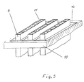
- FIG 3 is a perspective view of an arrangement of flat rod ends 9 in a support plate 10.
- Each rod 9 has six through openings 11 here.
- the rod ends 9 are in the Support plate 10 positioned such that they protrude from the front of the support plate 10.
- the openings of the support plate 10 (not visible) have extensions 12 towards the end face which are designed such that they have the shape of an elongated truncated pyramid.
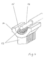
- FIG. 4 shows a further perspective illustration of a possible arrangement of flat bars 13, the ends of which have the contour of a circular ring segment, in a correspondingly shaped support plate 14. These rods 13 also have a plurality of through openings 16. A heating rod 16, which is brought into the position shown in FIG. 4 for thermal treatment, is particularly suitable for the thermal treatment of an arrangement shown in FIG.
- the openings of the support plate 17 can also be designed in such a way that they are extended towards the end face beyond the actual support plate body 17 by webs 18.
- a particularly strong connection between the rod ends and the support plate is achieved.
- the support plate 19 has an extension 20 towards the front side, which in the case of round bars can be described as conical, in the case of flat bars as a truncated pyramid.
- 20 webs 21 are arranged in the extension, which ensure a particularly intimate, solid fusion with the rod ends. The webs 21 expand together with the tube ends during the thermal treatment, so that the webs 21 abut the extensions 20. After the thermal treatment, the webs 21 are fused to the support plate 19 and the pipe ends to the webs 21.
- FIGS. 7 to 13 show examples of possible embodiments of extensions of the support plate openings towards the end face.
- a rod end 24 is inserted into the support plate 23 such that the rod end 24 projects beyond the end face of the support plate 23.
- the support plate opening (not designated) has a continuous widening 22.
- the configuration of FIG. 2 results after the thermal treatment.
- FIGS. 8, 10, 11 and 12 show abrupt extensions 25, 31, 34 and 37 of the openings 27, 33, 36 and 39 in the support plates 26, 32, 35 and 38 respectively, while in FIGS. 9 and 13 continuous extensions 28 and 41 of the openings 30 and 44 in the support plates 29 and 42 are shown.
- the rod end 43 extends into the extension 41 of the support plate 42 without, however, projecting beyond the end face of the support plate 42.
Landscapes
- Engineering & Computer Science (AREA)
- Mechanical Engineering (AREA)
- Physics & Mathematics (AREA)
- Thermal Sciences (AREA)
- Health & Medical Sciences (AREA)
- Electromagnetism (AREA)
- Toxicology (AREA)
- General Engineering & Computer Science (AREA)
- Lining Or Joining Of Plastics Or The Like (AREA)
Claims (29)

Priority Applications (1)
| Application Number | Priority Date | Filing Date | Title |
|---|---|---|---|
| AT86116060T ATE55942T1 (de) | 1985-12-16 | 1986-11-20 | Verbinden von hohlprofilkoerpern mit einer kunststoffplatte, insbesondere zum herstellen von waermetauschern. |
Applications Claiming Priority (4)
| Application Number | Priority Date | Filing Date | Title |
|---|---|---|---|
| DE3544405 | 1985-12-16 | ||
| DE3544405 | 1985-12-16 | ||
| DE3614322 | 1986-04-28 | ||
| DE3614322 | 1986-04-28 |
Publications (3)
| Publication Number | Publication Date |
|---|---|
| EP0226825A2 EP0226825A2 (fr) | 1987-07-01 |
| EP0226825A3 EP0226825A3 (en) | 1988-10-26 |
| EP0226825B1 true EP0226825B1 (fr) | 1990-08-29 |
Family
ID=25838891
Family Applications (1)
| Application Number | Title | Priority Date | Filing Date |
|---|---|---|---|
| EP86116060A Expired - Lifetime EP0226825B1 (fr) | 1985-12-16 | 1986-11-20 | Liaison d'un profilé creux avec une plaque en matière plastique, en particulier pour la fabrication d'échangeurs de chaleur |
Country Status (4)
| Country | Link |
|---|---|
| US (1) | US4790372A (fr) |
| EP (1) | EP0226825B1 (fr) |
| DE (1) | DE3673780D1 (fr) |
| DK (1) | DK572786A (fr) |
Families Citing this family (28)
| Publication number | Priority date | Publication date | Assignee | Title |
|---|---|---|---|---|
| DE3723317A1 (de) * | 1987-07-15 | 1989-01-26 | Akzo Gmbh | Verfahren zum verschweissen von rohrenden mit einem rohrboden |
| DE3806517A1 (de) * | 1988-03-01 | 1989-09-14 | Akzo Gmbh | Rohrboden fuer waerme- und/oder stoffaustauscher, dessen verwendung sowie verfahren zu dessen herstellung |
| US5069277A (en) * | 1990-03-13 | 1991-12-03 | Diesel Kiki Co., Ltd. | Vehicle-loaded heat exchanger of parallel flow type |
| SE469855B (sv) * | 1992-02-06 | 1993-09-27 | Bjoern Hagert C O Aalander | Metod att tillverka plastvärmeväxlare genom värmehopsmältning av kanalplattors ändpartier och distansorgan |
| GB2273459A (en) * | 1992-12-21 | 1994-06-22 | Anthony Joseph Cesaroni | Bonding tubes to articles e.g in making panel heat exchangers. |
| US5397407A (en) * | 1994-01-12 | 1995-03-14 | Innovative Automation Inc. | Apparatus for cooling ultrasonic tube sealers |
| US5623988A (en) * | 1995-09-25 | 1997-04-29 | Gas Research Institute | Polymeric heat exchanger with ceramic material insert |
| US6001291A (en) * | 1996-02-07 | 1999-12-14 | Cesaroni; Anthony Joseph | Method of bonding tubes into an article |
| KR0165067B1 (ko) * | 1996-04-09 | 1999-01-15 | 구자홍 | 2열 플랫튜브형 열교환기 |
| JP3059393B2 (ja) * | 1996-11-26 | 2000-07-04 | 日本ピラー工業株式会社 | 熱交換器 |
| IT1295267B1 (it) * | 1997-10-03 | 1999-05-04 | Enichem Spa | Processo per preparare zeoliti legate |
| US6038768A (en) * | 1998-06-09 | 2000-03-21 | Fafco, Incorporated | Method and apparatus for coupling panel boards and tubing to a header pipe |
| JP2001165532A (ja) * | 1999-12-09 | 2001-06-22 | Denso Corp | 冷媒凝縮器 |
| US20020195240A1 (en) * | 2001-06-14 | 2002-12-26 | Kraay Michael L. | Condenser for air cooled chillers |
| EP1433036A4 (fr) * | 2001-10-01 | 2008-10-22 | Entegris Inc | Appareil de conditionnement de la temperature d'un fluide |
| KR101230694B1 (ko) * | 2003-12-22 | 2013-02-07 | 엔테그리스, 아이엔씨. | 포팅된 중공 도관을 구비한 교환 장치 |
| US20070289732A1 (en) * | 2004-03-11 | 2007-12-20 | Pillion John E | Apparatus for conditioning the temperature of a fluid |
| WO2005121585A1 (fr) * | 2004-06-09 | 2005-12-22 | Toyo Tire & Rubber Co., Ltd. | Procédé pour la fabrication d’un soufflet de joint en résine |
| US20060005955A1 (en) * | 2004-07-12 | 2006-01-12 | Orr Troy J | Heat exchanger apparatus and methods for controlling the temperature of a high purity, re-circulating liquid |
| US7458222B2 (en) * | 2004-07-12 | 2008-12-02 | Purity Solutions Llc | Heat exchanger apparatus for a recirculation loop and related methods and systems |
| WO2006059498A1 (fr) * | 2004-11-30 | 2006-06-08 | Matsushita Electric Industrial Co., Ltd. | Echangeur de chaleur et son procede de fabrication |
| CA2538761A1 (fr) * | 2005-03-08 | 2006-09-08 | Anthony Joseph Cesaroni | Methode de scellement de tubes d'echangeur thermique |
| EP1957928B1 (fr) * | 2005-12-09 | 2012-02-01 | Siemens Canada Limited | Refroidisseur intermediaire en plastique soude au laser |
| DE102006004828A1 (de) * | 2006-01-31 | 2007-08-02 | Herbst, Donald, Dipl.-Ing. | Kunststoffrohr für die Durchleitung eines Heiz- oder Kühlmediums, unter Verwendung derartiger Rohre hergestellte Matte sowie Verbindung zwischen der Stirnseite eines derartigen Rohres und einem Kunststoffkörper |
| KR100854572B1 (ko) * | 2006-08-11 | 2008-08-26 | 주식회사 엘지화학 | 플라스틱 열교환기의 및 그의 제조방법 |
| US20100139902A1 (en) * | 2008-12-05 | 2010-06-10 | Baylis Bobbye K | Plastic heat exchanger |
| FR2958385B1 (fr) * | 2010-03-31 | 2013-01-18 | Valeo Systemes Thermiques | Echangeur de chaleur a performances accrues |
| US9227353B2 (en) * | 2012-11-08 | 2016-01-05 | Solar Hydronics Corporation | Molding apparatus and method for operating same |
Family Cites Families (23)
| Publication number | Priority date | Publication date | Assignee | Title |
|---|---|---|---|---|
| US2538808A (en) * | 1950-03-24 | 1951-01-23 | Westinghouse Electric Corp | Sealed heater element and the like |
| US2876496A (en) * | 1955-12-16 | 1959-03-10 | Dade Reagents Inc | Process for making tubes |
| US2966373A (en) * | 1959-02-02 | 1960-12-27 | Ici Ltd | Tubular inserts |
| DE1209725B (de) * | 1960-03-11 | 1966-01-27 | Hans Joachim Dietzsch G M B H | Verfahren zur Oberflaechenbehandlung eines Koerpers aus gebuendelten Hohlfaeden |
| FR1369997A (fr) * | 1963-04-16 | 1964-08-21 | Tecalemit Sa | Procédé de formage sur matière thermo sensible |
| US3347728A (en) * | 1964-07-29 | 1967-10-17 | Gen Motors Corp | Method for forming joints in tubes |
| NL151792C (fr) * | 1965-01-14 | |||
| GB1099064A (en) * | 1966-05-10 | 1968-01-10 | Perry Ltd E S | Sealing of tubes of plastics material |
| US3462362A (en) * | 1966-07-26 | 1969-08-19 | Paul Kollsman | Method of reverse osmosis |
| US3438434A (en) * | 1967-10-19 | 1969-04-15 | Du Pont | Subdivided heat exchanger tube bundle assembly providing longitudinally distributed fluid bypass and distributing channels |
| US3616022A (en) * | 1968-08-06 | 1971-10-26 | Du Pont | Method of making heat exchange components |
| US3592261A (en) * | 1968-11-25 | 1971-07-13 | Lummus Co | Heat exchanger |
| US3741849A (en) * | 1971-02-08 | 1973-06-26 | Angelica Corp | Method of joining tubes to manifold |
| DE2204167A1 (de) * | 1972-01-29 | 1973-08-09 | Krupp Gmbh | Waermetauscher und verfahren zu seiner herstellung |
| GB1478015A (en) * | 1973-07-27 | 1977-06-29 | Delanair Ltd | Heat exchanger |
| DE2502181A1 (de) * | 1975-01-21 | 1976-07-22 | Becker Pruente Gmbh | Verfahren zum verbinden von rohren aus thermoplastischem kunststoff mit plattenboeden aus thermoplastischem kunststoff |
| DE2603615C3 (de) * | 1976-01-30 | 1979-06-13 | Masashi Daito Osaka Kato (Japan) | Vorrichtung zum Herstellen eines Rohrbfindels aus thermoplastischem Kunststoff |
| DE2612514B1 (de) * | 1976-03-24 | 1977-09-29 | Cenrus Ag | Rohrboden eines rohrbuendel-waermeaustauschers |
| DE2734958A1 (de) * | 1977-08-03 | 1979-02-15 | Froehlich Air Ag | Verfahren zur herstellung eines rohrwaermetauschers und nach diesem verfahren hergestellter rohrwaermetauscher |
| US4219525A (en) * | 1978-12-01 | 1980-08-26 | Greenspan Donald J | Method and apparatus for closing tubes |
| US4300971A (en) * | 1979-04-23 | 1981-11-17 | Mcalister Roy E | Method for manifolding multiple passage solar panel |
| US4481057A (en) * | 1980-10-28 | 1984-11-06 | Oximetrix, Inc. | Cutting device and method of manufacture |
| DE3338157A1 (de) * | 1983-10-20 | 1985-05-02 | Akzo Gmbh, 5600 Wuppertal | Verfahren zum dichten verbinden von rohrenden in rohrboeden |
-
1986
- 1986-11-20 EP EP86116060A patent/EP0226825B1/fr not_active Expired - Lifetime
- 1986-11-20 DE DE8686116060T patent/DE3673780D1/de not_active Expired - Lifetime
- 1986-11-28 DK DK572786A patent/DK572786A/da not_active Application Discontinuation
- 1986-12-15 US US06/941,377 patent/US4790372A/en not_active Expired - Fee Related
Also Published As
| Publication number | Publication date |
|---|---|
| DE3673780D1 (de) | 1990-10-04 |
| DK572786D0 (da) | 1986-11-28 |
| US4790372A (en) | 1988-12-13 |
| EP0226825A3 (en) | 1988-10-26 |
| EP0226825A2 (fr) | 1987-07-01 |
| DK572786A (da) | 1987-06-17 |
Similar Documents
| Publication | Publication Date | Title |
|---|---|---|
| EP0226825A2 (fr) | Liaison d'un profilé creux avec une plaque en matière plastique, en particulier pour la fabrication d'échangeurs de chaleur | |
| EP1358855B1 (fr) | Procédé pour la production d'objets par formage de formes libres lors d'un procédé de frittage au laser | |
| EP0168558B1 (fr) | Procédé et dispositif pour la fabrication d'échangeurs de chaleur et/ou de matière comportant des tuyaux | |
| DE69502716T2 (de) | Oszillierendes reibungsschweissen | |
| EP0176729B1 (fr) | Echangeur de chaleur, ainsi que procédé et dispositif pour sa fabrication | |
| EP0243574B1 (fr) | Echangeur de chaleur et procédé de fabrication d'échangeurs de chaleur | |
| DE3445656A1 (de) | Schaumstoff-schallabsorptionskoerper | |
| DE2129170A1 (de) | Systembauteil | |
| DE3518441C2 (de) | Verfahren zum Herstellen eines Verformlings für das Blasformen eines Hohlkörpers | |
| DE102017205765A1 (de) | Verfahren zum Verschweißen von Bauteilen | |
| EP0243575B1 (fr) | Echangeur de chaleur et/ou de matière et procédé de fabrication des échangeurs de chaleur et/ou de matière | |
| EP0299182B1 (fr) | Procédé pour souder des extrémités de tuyaux à un plateau à tubes | |
| DE69405171T2 (de) | Längliche kunststoffgegenstandsverbindung und verfahren und vorrichtung zu deren herstellung | |
| WO1988003376A1 (fr) | Procede pour la fabrication d'articles a soies | |
| EP1052079A1 (fr) | Procédé et dispositif de fabrication d'un élément profilé creux en matière thermoplastique | |
| DE8611642U1 (de) | Wärmetauscher | |
| DE19725326C2 (de) | Verfahren zum Herstellen einer Matte mit dünnwandigen Kunststoffrohren | |
| EP0140069A2 (fr) | Procédé pour joindre étanchement des extrémités de tuyau à des plaques tubulaires | |
| DE3636177A1 (de) | Verfahren, insbesondere zum herstellen eines waermetauschers sowie waermetauscher | |
| WO2022058181A1 (fr) | Dispositif de régulation de la température d'un élément et son procédé de fabrication | |
| WO2007088072A1 (fr) | Liaison entre le cote frontal d'un tube en matiere synthetique et un corps en matiere synthetique | |
| DE3138621A1 (de) | Waermeaustauscher | |
| DE19854173C2 (de) | Metallschaumformkörper | |
| DE2656804A1 (de) | Verfahren zum t- oder stumpfschweissen von laminiertem vollsynthetischem material | |
| DE19638715C2 (de) | Verfahren zum Zusammenschweissen von Kunststoff-Rohrleitungen und nach dem Verfahren hergestellter, mattenartiger Wärmetauscher für Kühl- und/oder Heizzwecke |
Legal Events
| Date | Code | Title | Description |
|---|---|---|---|
| PUAI | Public reference made under article 153(3) epc to a published international application that has entered the european phase |
Free format text: ORIGINAL CODE: 0009012 |
|
| AK | Designated contracting states |
Kind code of ref document: A2 Designated state(s): AT BE CH DE FR GB IT LI NL SE |
|
| PUAL | Search report despatched |
Free format text: ORIGINAL CODE: 0009013 |
|
| AK | Designated contracting states |
Kind code of ref document: A3 Designated state(s): AT BE CH DE FR GB IT LI NL SE |
|
| 17P | Request for examination filed |
Effective date: 19881102 |
|
| 17Q | First examination report despatched |
Effective date: 19890210 |
|
| GRAA | (expected) grant |
Free format text: ORIGINAL CODE: 0009210 |
|
| AK | Designated contracting states |
Kind code of ref document: B1 Designated state(s): AT BE CH DE FR GB IT LI NL SE |
|
| PG25 | Lapsed in a contracting state [announced via postgrant information from national office to epo] |
Ref country code: IT Free format text: LAPSE BECAUSE OF FAILURE TO SUBMIT A TRANSLATION OF THE DESCRIPTION OR TO PAY THE FEE WITHIN THE PRE;WARNING: LAPSES OF ITALIAN PATENTS WITH EFFECTIVE DATE BEFORE 2007 MAY HAVE OCCURRED AT ANY TIME BEFORE 2007. THE CORRECT EFFECTIVE DATE MAY BE DIFFERENT FROM THE ONE RECORDED.SCRIBED TIME-LIMIT Effective date: 19900829 |
|
| REF | Corresponds to: |
Ref document number: 55942 Country of ref document: AT Date of ref document: 19900915 Kind code of ref document: T |
|
| ET | Fr: translation filed | ||
| GBT | Gb: translation of ep patent filed (gb section 77(6)(a)/1977) | ||
| REF | Corresponds to: |
Ref document number: 3673780 Country of ref document: DE Date of ref document: 19901004 |
|
| PG25 | Lapsed in a contracting state [announced via postgrant information from national office to epo] |
Ref country code: AT Effective date: 19901120 |
|
| PLBE | No opposition filed within time limit |
Free format text: ORIGINAL CODE: 0009261 |
|
| STAA | Information on the status of an ep patent application or granted ep patent |
Free format text: STATUS: NO OPPOSITION FILED WITHIN TIME LIMIT |
|
| 26N | No opposition filed | ||
| EAL | Se: european patent in force in sweden |
Ref document number: 86116060.4 |
|
| PGFP | Annual fee paid to national office [announced via postgrant information from national office to epo] |
Ref country code: SE Payment date: 19960927 Year of fee payment: 11 |
|
| PGFP | Annual fee paid to national office [announced via postgrant information from national office to epo] |
Ref country code: GB Payment date: 19961009 Year of fee payment: 11 |
|
| PGFP | Annual fee paid to national office [announced via postgrant information from national office to epo] |
Ref country code: FR Payment date: 19961011 Year of fee payment: 11 Ref country code: CH Payment date: 19961011 Year of fee payment: 11 |
|
| PGFP | Annual fee paid to national office [announced via postgrant information from national office to epo] |
Ref country code: DE Payment date: 19961014 Year of fee payment: 11 |
|
| PGFP | Annual fee paid to national office [announced via postgrant information from national office to epo] |
Ref country code: BE Payment date: 19961021 Year of fee payment: 11 |
|
| PGFP | Annual fee paid to national office [announced via postgrant information from national office to epo] |
Ref country code: NL Payment date: 19961127 Year of fee payment: 11 |
|
| PG25 | Lapsed in a contracting state [announced via postgrant information from national office to epo] |
Ref country code: GB Free format text: LAPSE BECAUSE OF NON-PAYMENT OF DUE FEES Effective date: 19971120 |
|
| PG25 | Lapsed in a contracting state [announced via postgrant information from national office to epo] |
Ref country code: SE Free format text: LAPSE BECAUSE OF NON-PAYMENT OF DUE FEES Effective date: 19971121 |
|
| PG25 | Lapsed in a contracting state [announced via postgrant information from national office to epo] |
Ref country code: CH Free format text: LAPSE BECAUSE OF NON-PAYMENT OF DUE FEES Effective date: 19971130 Ref country code: BE Free format text: LAPSE BECAUSE OF NON-PAYMENT OF DUE FEES Effective date: 19971130 Ref country code: LI Free format text: LAPSE BECAUSE OF NON-PAYMENT OF DUE FEES Effective date: 19971130 Ref country code: FR Free format text: THE PATENT HAS BEEN ANNULLED BY A DECISION OF A NATIONAL AUTHORITY Effective date: 19971130 |
|
| BERE | Be: lapsed |
Owner name: AKZO N.V. Effective date: 19971130 |
|
| PG25 | Lapsed in a contracting state [announced via postgrant information from national office to epo] |
Ref country code: NL Free format text: LAPSE BECAUSE OF NON-PAYMENT OF DUE FEES Effective date: 19980601 |
|
| GBPC | Gb: european patent ceased through non-payment of renewal fee |
Effective date: 19971120 |
|
| REG | Reference to a national code |
Ref country code: CH Ref legal event code: PL |
|
| PG25 | Lapsed in a contracting state [announced via postgrant information from national office to epo] |
Ref country code: DE Free format text: LAPSE BECAUSE OF NON-PAYMENT OF DUE FEES Effective date: 19980801 |
|
| EUG | Se: european patent has lapsed |
Ref document number: 86116060.4 |
|
| NLV4 | Nl: lapsed or anulled due to non-payment of the annual fee |
Effective date: 19980601 |
|
| REG | Reference to a national code |
Ref country code: FR Ref legal event code: ST |