EP0168598B1 - Rotierender Ausbrecher - Google Patents
Rotierender Ausbrecher Download PDFInfo
- Publication number
- EP0168598B1 EP0168598B1 EP85106327A EP85106327A EP0168598B1 EP 0168598 B1 EP0168598 B1 EP 0168598B1 EP 85106327 A EP85106327 A EP 85106327A EP 85106327 A EP85106327 A EP 85106327A EP 0168598 B1 EP0168598 B1 EP 0168598B1
- Authority
- EP
- European Patent Office
- Prior art keywords
- piece
- cut
- cylinder
- cylinders
- web
- Prior art date
- Legal status (The legal status is an assumption and is not a legal conclusion. Google has not performed a legal analysis and makes no representation as to the accuracy of the status listed.)
- Expired - Lifetime
Links
- 239000000463 material Substances 0.000 claims abstract description 11
- 238000000034 method Methods 0.000 claims description 4
- 230000000717 retained effect Effects 0.000 claims 1
- 238000012986 modification Methods 0.000 description 4
- 230000004048 modification Effects 0.000 description 4
- 239000000853 adhesive Substances 0.000 description 2
- 230000001070 adhesive effect Effects 0.000 description 2
- 239000002390 adhesive tape Substances 0.000 description 2
- 238000010276 construction Methods 0.000 description 2
- 239000002184 metal Substances 0.000 description 2
- 229910000831 Steel Inorganic materials 0.000 description 1
- 230000001154 acute effect Effects 0.000 description 1
- 239000011111 cardboard Substances 0.000 description 1
- 239000013013 elastic material Substances 0.000 description 1
- 239000011888 foil Substances 0.000 description 1
- 238000012423 maintenance Methods 0.000 description 1
- 238000004519 manufacturing process Methods 0.000 description 1
- 239000000123 paper Substances 0.000 description 1
- 239000011087 paperboard Substances 0.000 description 1
- 239000004033 plastic Substances 0.000 description 1
- 239000002985 plastic film Substances 0.000 description 1
- 229920006255 plastic film Polymers 0.000 description 1
- 239000012858 resilient material Substances 0.000 description 1
- 239000010959 steel Substances 0.000 description 1
Images

Classifications
-
- B—PERFORMING OPERATIONS; TRANSPORTING
- B26—HAND CUTTING TOOLS; CUTTING; SEVERING
- B26D—CUTTING; DETAILS COMMON TO MACHINES FOR PERFORATING, PUNCHING, CUTTING-OUT, STAMPING-OUT OR SEVERING
- B26D7/00—Details of apparatus for cutting, cutting-out, stamping-out, punching, perforating, or severing by means other than cutting
- B26D7/18—Means for removing cut-out material or waste
- B26D7/1836—Means for removing cut-out material or waste by pulling out
-
- Y—GENERAL TAGGING OF NEW TECHNOLOGICAL DEVELOPMENTS; GENERAL TAGGING OF CROSS-SECTIONAL TECHNOLOGIES SPANNING OVER SEVERAL SECTIONS OF THE IPC; TECHNICAL SUBJECTS COVERED BY FORMER USPC CROSS-REFERENCE ART COLLECTIONS [XRACs] AND DIGESTS
- Y10—TECHNICAL SUBJECTS COVERED BY FORMER USPC
- Y10T—TECHNICAL SUBJECTS COVERED BY FORMER US CLASSIFICATION
- Y10T83/00—Cutting
- Y10T83/04—Processes
- Y10T83/0448—With subsequent handling [i.e., of product]
- Y10T83/0467—By separating products from each other
-
- Y—GENERAL TAGGING OF NEW TECHNOLOGICAL DEVELOPMENTS; GENERAL TAGGING OF CROSS-SECTIONAL TECHNOLOGIES SPANNING OVER SEVERAL SECTIONS OF THE IPC; TECHNICAL SUBJECTS COVERED BY FORMER USPC CROSS-REFERENCE ART COLLECTIONS [XRACs] AND DIGESTS
- Y10—TECHNICAL SUBJECTS COVERED BY FORMER USPC
- Y10T—TECHNICAL SUBJECTS COVERED BY FORMER US CLASSIFICATION
- Y10T83/00—Cutting
- Y10T83/202—With product handling means
- Y10T83/2074—Including means to divert one portion of product from another
- Y10T83/2079—Remaining or re-inserted product portion from base material
Definitions
- This invention relates to rotary die cutting of blanks from thin sheets or webs of material such as paper, paper board, cardboard, plastic film, metal foil, sheet metal, and the like. More particularly, this invention relates to stripping or removing cut portions or pieces from a web of material.
- a web of material was first cut by being passed between a pair of rotary cutting dies having blades which severed or cut portions of pieces of the web and then some of the cut portions or pieces were removed by passing the cut web between a separate pair of stripping cylinders or rolls at least one of which had a plane cylindrical surface.
- the cut pieces to be removed were transferred onto the cylindrical surface, and after the cylinder rotated sufficiently to carry the piece away from the web, it was removed from the cylinder by a stripper plate having a leading sharp edge bearing on the plane clyindrical surface.
- the problem to be solved by the invention is to be free from that restriction, i. e. both rotary die cylinders can have cutting blades thereon.
- a cut portion or piece of a web of material is transferred and releasably secured to a rotating cylinder which does not have a circumferentially continuous plane cylindrical surface, the transferred portion is generally pivoted with respect to the cylinder to move its leading edge generally radially outward from the periphery of the cylinder, and a stripping element such as a slider plate or comb passes between the rotating cylinder and the leading edge of the pivoted portion to remove the portion from the cylinder.
- the transferred portion is pivoted about a point or line intermediate its leading and trailing edges by moving a trailing part of the portion into a recess or pocket in the cylinder.
- the trailing part is forced into the pocket by a projection on a second cylinder which corotates with the first cylinder with the web passing between the cylinders.
- the cylinders also have severing blades thereon which cut at least the portions to be removed before they are removed.
- This invention has the advantage to provide a stripper mechanism for removing cut pieces of a web which can be embodied directly in a pair of rotary cutting dies having coacting severing blades on both dies, unfailingly, reliably, readily and easily removes cut pieces, can remove cut pieces which are scrap and/or desired parts, is relatively simple, rugged, durable and of economical manufacture and assembly, and require little service or maintenance.
- the invention concerns also a method for removing pieces cut from a web of material according to claim 10.
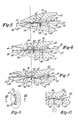
- Figure 1 illustrates a pair of rotary die cylinders 10 and 12 embodying this invention.
- the die cylinders When rotating the die cylinders cut elongate parts or blanks 14 and scrap portions 16 and 18 (Fig. 2) from a web of material 20 passing between the cylinders.
- the web 20 As the web 20 is fed into the dies, it is supported on a slide plate 22 and as the cut parts 14 emerge from the dies, they are supported by a slide plate 24 and fed into a conveyor assembly 26.
- the cut parts 14 are received between and carried away by a pair of driven continuous belts or webs 28 each received on an idler pulley 30.
- the parts 14 are cut from the web 20 by serving blades disposed on one or both of the die cylinders 10 and 12.
- the blades are constructed and arranged on the cylinders so that multiple parts are cut with each complete revolution of the cylinders.
- the blades are arranged on the cylinders 10 and 12 so that they cut three parts 14 across the width of the cylinders and four parts in each path or tack around the circumference of the cylinders for a total of twelve parts for each complete revolution of the cylinders.
- the die cylinders 10 and 12 have pairs of coacting elongate severing blades each disposed on one of the die cylinders with their axes on generally opposite sides of the cutting line or line of severance of the web.
- the upper die cylinder 10 has severing blades 32, 34, 36, 38, 40, 42, 44 and 46 which respectively coact with corresponding severing blades of the lower die 32', 34', 36', 40', 42', 44' and 46'.
- each blade is disposed on opposite sides of the line of severance and preferably each blade is a land disposed on the periphery of its associated cylinder and having in cross section an outer face and spaced apart generally depending side faces defining a pair of spaced apart edges.
- the side faces are inclined toward each other at an acute included angle and each inclined to its associated outer face at an obtuse included angle.
- the blades of each pair are constructed, arranged and positioned on their respective die cylinders such that during corotation of the die cylinders 10 and 12 the immediately adjacent edges of the blades of each pair cut the web therebetween along a predetermined line of severance while the other edges of the blades of each pair are on generally opposite sides of the line of severance.
- each side face is inclined to its outer face at an obtuse included angle which is usually in the range of about 100° to 120° and preferably about 105° to 110°.
- the transverse width of the outer face of each land is in the range of about 0,25 to 3,16 mm, typically about 0,5 to 1,5 mm, and preferably about 0,76 to 1,02 mm.
- the radial height of the lands is about 1,27 to 1,5 mm, and preferably about 1,52 to 2,03 mm.
- scrap pieces 16 and 18 are removed after being cut from the web by a stripper mechanism 50.
- the scrap pieces 16 and 18 are removed in the same manner and hence, only the removal of a scrap piece 16 will be described in detail.
- each piece 16 is releasably secured to the lower die 12 for rotation therewith by at least one pin 52, pivoted so that its leading edge 54 is raised above the lower die 12 by cooperation of a finger 56 on the upper die 10 (Fig. 7), and then removed from the lower die by the cooperation of a comb or stripping plate 58 (Fig. 8).
- each piece 16 is secured to the lower die 12 before it is completely cut from the web 20.
- Each piece is secured by at least one pin 52 piercing the piece.
- pins 52 are about 1,27 to 2,03 mm in diameter and holes 60 are about 4,57 to 6,34 mm in diameter.
- the leading portion of the piece is preferably received on a prominence 62 on the lower die, the trailing portion of which provides a line or edge 64 about which the piece 16 is pivoted.
- the pins 52 are threaded into the die 12 immediately adjacent this trailing edge 64.
- a recess 66 is provided between the prominence and the severing blade.
- the outer face of the prominence 62 lies radially inward of the outer faces of the adjacent severing blades a distance approximately equal to the thickness of the web 20 being cut.
- a recess or pocket 68 is formed in the lower die behind the trailing edge of the prominence to receive a trailing portion of the piece when it is displaced into the pocket by the finger 56.
- this pocket 68 has a radial depth about equal to the height of the severing blades of the lower cylinder 12.
- the prominence 62, pocket 68, and finger 56 are constructed, arranged and dimensioned so that they move the leading edge 54 of the piece away from the cylinder sufficiently to provide a clearance between them which is usually in the range of 0,127 to 2,539 mm, typically about 0,25 to 1,27 mm, and preferably about 0,5 to 1,0 mm.
- each finger 56 can be a separate piece of rigid material such as steel secured to the cylinder 10 by bolts or the like.
- each finger is a separate piece of an elastic or resilient material such as rubber, plastic, elastic, or the like secured to the cylinder by an adhesive or double back adhesive tape. Suitable adhesive tape is available from 3M Company of Minneapolis, Minnesota and Morgan Adhesive Company of Stow, Ohio.
- the stripper plate 58 is mounted as shown in Figures 1 and 8 angularly downstream from the position at which the pieces are cut from the web.
- the stripper plate 58 is mounted so that its tip or leading edge 70 passes between the leading edge 54 of the pivoted piece 16 and the lower die cylinder as the piece 16 is advanced toward the stripper plate.
- the stripper plate 58 is positioned so that its outer face 72 is generally tangent to the periphery of the lower die.
- the stripper plate has elongate clearance slots 74 in its leading edge through which the tips of the pins 54 pass as they are advanced by the cylinder.
- the stripper plate is mounted in fixed relation to the lower cylinder with a slight clearance between the stripper plate and the cylinder.
- FIGS 9 and 10 illustrate a modification in the way pieces 16 are secured to the lower die 12 so that the pieces can be secured without being pierced or damaged by any pins 52, clamps, or the like.
- vacuum ports 76 open into the upper face of the prominence 62 adjacent its trailing edge 64 and are connected to a source of vacuum 78. These vacuum ports are used in lieu of the pins 52 to releasably secure parts 16 to the lower die cylinder.
- this modification is identical to the cutting and stripping dies of Figures 1-8. Because vacuum ports eliminate piercing or any physical damage to the pieces 16, they are a particularly desirable way of releasably securing pieces which are not scrap but cut parts or blanks to be used in making articles.
- dies 10 and 12 are mounted for corotation with a web 20 passing between them as shown in Figure 1.
- the dies rotate in unison with the severing blades moving at the same surface speed and in the same direction when they engage the web 20, the blades cut parts 14 and scrap pieces 16 and 18 from the web.
- parts 14 emerge from the dies, pass over the slide 24 and enter the conveyor 26 which carries them away.
- each piece of scrap 16 and 18 is removed in the same manner, removal of only one piece of scrap 16 will be described in detail.
- each piece of scrap 16 and 18 is releasably secured to the lower die 12 for rotation therewith by being pierced by one or more pins 52.
- Each pin 52 is forced through a piece of scrap by rotation of the dies which causes the pin 52 and a generally opposed portion of the upper die 10 to move generally radially toward each other with the piece of scrap between them.
- the leading edge 54 of the piece of scrap is lifted and moved away from the lower die by pivoting the piece of scrap (Fig.
- the piece of scrap is pivoted by rotation of the dies which causes the finger 56 of the upper die and the underlying pocket 68 of the lower die to move toward each other with a trailing portion of the piece of scrap between them which is engaged by the finger.
- the piece of scrap 16 is completely cut or severed from the web 20 and carried by the lower die away from the web and the path of travel of the cut parts 14.
- the scrap is carried away, it is removed from the lower die by the cooperation of the stripper comb or plate 58 and the lower die.
- the sharp edge 70 of the stripper plate passes between the lower die and the raised leading edge 54 of the scrap piece.
- the pin 54 passes through the slot 74 in the stripper plate, it is withdrawn from and thereby releases the scrap piece which passes over the upper face 72 of the plate and is thereby removed from the lower die.
- stripping mechanism 50 has been described as being embodied in a pair of cutting die cylinders, it will be apparent that it can also be embodied in a separate pair of cylinders disposed downstream from a pair of cutting cylinders or other cutting dies and receiving the web after it has been cut.
- this stripping mechanism can also be used to cause each row of parts to be directed into separate conveyor systems or to separate every other part in a row of cut parts or to remove parts produced by a single cavity of the cutting dies, and the like.
- this stripping mechanism may be used in many applications where it is desirable to remove one or more pieces from a web of cut material.
Landscapes
- Life Sciences & Earth Sciences (AREA)
- Forests & Forestry (AREA)
- Engineering & Computer Science (AREA)
- Mechanical Engineering (AREA)
- Details Of Cutting Devices (AREA)
- Perforating, Stamping-Out Or Severing By Means Other Than Cutting (AREA)
- Hydraulic Motors (AREA)
- Supercharger (AREA)
- Polysaccharides And Polysaccharide Derivatives (AREA)
- Acyclic And Carbocyclic Compounds In Medicinal Compositions (AREA)
- Mechanical Treatment Of Semiconductor (AREA)
- Mechanisms For Operating Contacts (AREA)
- Eye Examination Apparatus (AREA)
- Lubricants (AREA)
Claims (12)
- Stanzmaschine zur Schneidbearbeitung von Bahnen (20) an einer Stanzstelle und Entfernen von ausgestanzten Stücken (16, 18) mit folgenden Merkmalen:a) zwei drehbare Stanzzylinder (10, 12) arbeiten miteinander, um eine dazwischen laufende Bahn (20) zu stanzen,b) eine lösbare Befestigungseinrichtung (52; 76) für die ausgestanzten Stücke (16, 18) ist auf dem einen der drehbaren Stanzzylinder (12) angeordnet, der die Stanzstücke (16, 18) von der Bahn (20) fortträgt und deshalb als Stanzstück-Tragzylinder (12) bezeichnet wird, undd) ein Ausbrecher (58) ist stromab von der Stanzstelle angeordnet und weist eine vordere scharfe Kante (70) benachbart dem Stanzstück-Tragzylinder (12) auf, um die Stanzstücke (16, 18) von dem Zylinder (12) zu lösen und zu entfernen,dadurch gekennzeichnet, daßc) ein drehbarer Zylinder (10), der nicht der Stanzstück-Tragzylinder (12) ist, mindestens ein Finger oder einen Vorsprung (56) aufweist, der so angeordnet und ausgebildet ist, daß er auf die Stanzstücke (16, 18) oder auf die Bahn (20) drückt, um das werdende oder fertige Stanzstück (16, 18) zu schwenken und deren vordere Kante (54) von der Oberfläche des Stanzstück-Tragzylinders (12) anzuheben, und daße) die Vorderkante (70) des Ausbrechers (58) radial von dem Stanzstück-Tragzylinder (12) radial entfernt ist, um zwischen dem Stanzstück-Tragzylinder (12) und der angehobenen Kante (54) des werdenden oder fertigen Stanzstückes (16, 18) hindurchzugreifen.
- Stanzmaschine nach Anspruch 1,
dadurch gekennzeichnet,
daß der andere drehbare Zylinder der Stanzzylinder (10) Ist, der mit dem als Stanzstück-Tragzylinder bezeichneten Stanzzylinder (12) zusammenarbeitet. - Stanzmaschine nach Anspruch 1 oder 2,
dadurch gekennzeichnet,
daß der Stanzstück-Tragzylinder (12) eine Aussparung (68) besitzt, worin der Finger (56) eintauchen kann, wenn die Zylinder (10, 12) rotieren, und das werdende oder fertige Stanzstuck (18) zwischen den Zylindern (10, 12) hindurchwandert. - Stanzmaschine nach Anspruch 1, 2 oder 3,
dadurch gekennzeichnet,
daß der Stanzstückzylinder (12) einen Vorsprung (62) aufweist, der unterhalb des Vorderteils des werdende oder fertigen Stanzstückes (16, 18) angeordnet ist und eine im wesentlichen rückwärtige Kante (64) aufweist, die zur Bildung einer Schwenkachse für das werdende oder fertige Stanzstück (16, 18) angeordnet ist, während der Finger (56) auf dieses einwirkt. - Stanzmaschine nach einem der vorhergehenden Anspruche 1 bis 4,
dadurch gekennzeichnet,
daß die Befestigungseinrichtung (52, 76) so ausgebildet und angeordnet ist, daß sie das werdende Stück (16, 18) an dem Stanzstück-Tragzylinder (12) sichert, bevor das Stück (16, 18) vollständig von der Bahn (20) abgetrennt wird. - Stanzmaschine nach einem der Anspruche 1 bis 5,
worin die lösbare Befestigungseinrichtung durch mindestens einen Stift (52) gekennzeichnet ist, der so ausgebildet und angeordnet ist, daß er das Stanzstück (16, 18) aufspießt, wenn das Stanzstück (16, 18) über den Stift (52) durch die Zusammenwirkung eines Teils des anderen Zylinders (10) gepreßt wird, wenn das Stanzstück (16, 18) zwischen den Zylindern (10, 12) hindurchwandert. - Stanzmaschine nach Anspruch 6,
gekennzeichnet durch eine Tasche (60) in dem anderen Zylinder (10), in welchem der Stift (52) hineinreicht, wenn er zwischen den Zylindern (10, 12) hindurchwandert. - Stanzmaschine nach einem der Ansprüche 1 bis 5,
worin die lösbare Befestigungseinrichtung durch mindestens eine Vakuumöffnung (76) in dem Stanzstück-Tragzylinder (12) gekennzeichnet ist. - Stanzmaschine nach einem der vorhergehenden Anspruche 1 bis 8,
dadurch gekennzeichnet,
daß mindestens ein Paar von miteinander zusammenwirkenden Trennmessern (34, 34'; 36, 36'; 40, 40'; 42, 42'; 44, 44'; 46, 46') vorgesehen sind, daß jedes der Messer auf einem der Zylinder (10, 12) mit seinen Achsen auf im großen und ganzen entgegengesetzten Seiten einer vorbestimmten Trennlinie zum vollständigen Trennen der Stanzstücke (16, 18) von der Bahn (20) angeordnet sind,
daß jedes Trennmesser ein im wesentlichen radial nach außen vorstehender Bereich aus dem Hauptkörper des zugeordneten Zylinders (10, 12) aufweist und
daß die lösbare Befestigungseinrichtung (52) so konstruiert und angeordnet ist, daß sie die Stanzstücke (16, 18) an den Stanzstück-Tragzylinder (12) anheftet, bevor das Stanzstück (16, 18) vollständig von der Bahn (20) durch die zusammenwirkenden Trennmesser (34, 34'; 36. 36'; 40, 40'; 42, 42'; 44, 44'; 46, 46') abgetrennt ist. - Verfahren zur Entfernung von Stanzstücken von einer Materialbahn mit folgenden Schritten:a) zwei zusammenwirkende Stanzzylinder (10, 12) rotieren zusammen, um eine dazwischen wandernde Bahn (20) zu schneiden,b) auf einem (12) der Zylinder (12, 10) wird ein ausgestanztes oder aus der Bahn (20) auszustanzendes Stück (16, 18) übertragen, indem dieses Stanzstück (16, 18) an einem der Zylinder (12) lösbar angeheftet wird, so daß dieser das Stanzstück (16, 18) von der Bahn (20) fortführt, wobei das Stanzstück (16, 18) eine Vorderkante aufweist und der eine Zylinder (12) als der Stanzstück-Tragylinder (12) bezeichnet wird,c) die Vorderkante (54) des Stanzstücks (16, 18) wird von der Oberfläche des Stanzstück-Tragzylinders (12) an einer ersten Stelle des Umlaufs angehoben, indem das Stanzstück (16, 18) geschwenkt wird, während es auf dem Stanzstück-Tragzylinder (12) verbleibt, undd) an einer zweiten Stelle des Umlaufs stromab von der ersten Umlaufstelle wird das Stück (16, 18) von dem Stanzstück-Tragzylinder (12) entfernt, indem das Stanzstück (16, 18) entlang eines Weges bewegt wird, der im wesentlichen tangential zum äußeren Umfang des Stanzstück-Tragzylinders (12) an der zweiten Umlaufstelle verläuft.
- Verfahren nach Anspruch 10,
dadurch gekennzeichnet,
daß mindestens ein Paar der Trennmesser (34, 34'; 36, 36'; 40, 40'; 42, 42'; 44, 44'; 46, 46') mit einem Trennmesser auf jedem der Zylinder (10, 12) vertreten ist und zum Ausschneiden des Stanzstücks (16, 18) von der Bahn verwendet wird, wenn diese zwischen den Zylindern (10, 12) hindurchwandert und
daß der Schritt b) - Anheften der Stücke (16, 18) an dem Stanzstück-Tragzylinder (12) - ausgeführt wird, bevor das Stanzstück (16, 18) vollständig von der Bahn (20) durch die Trennmesser (34, 34'; 36, 36'; 40, 40'; 42, 42'; 44, 44'; 46, 46') abgetrennt ist. - Verfahren nach Anspruch 10 oder 11,
dadurch gekennzeichnet,
daß die Vorderkante (54) des Stanzstücks (16, 18) durch einen Finger oder einen Vorsprung (56) verschwenkt wird, wenn die Zylinder (10, 12) zusammenarbeiten, und
daß der Finger oder der Vorsprung (56) auf einen rückwärtigen Teil des Stanzstücks (16, 18) drückt, so lange das Stanzstück (16, 18) zwischen den Zylindern (10, 12) hindurchwandert.
Priority Applications (1)
| Application Number | Priority Date | Filing Date | Title |
|---|---|---|---|
| AT85106327T ATE69759T1 (de) | 1984-06-19 | 1985-05-23 | Rotierender ausbrecher. |
Applications Claiming Priority (2)
| Application Number | Priority Date | Filing Date | Title |
|---|---|---|---|
| US622078 | 1984-06-19 | ||
| US06/622,078 US4561334A (en) | 1984-06-19 | 1984-06-19 | Rotary stripper |
Publications (3)
| Publication Number | Publication Date |
|---|---|
| EP0168598A2 EP0168598A2 (de) | 1986-01-22 |
| EP0168598A3 EP0168598A3 (en) | 1988-03-23 |
| EP0168598B1 true EP0168598B1 (de) | 1991-11-27 |
Family
ID=24492854
Family Applications (1)
| Application Number | Title | Priority Date | Filing Date |
|---|---|---|---|
| EP85106327A Expired - Lifetime EP0168598B1 (de) | 1984-06-19 | 1985-05-23 | Rotierender Ausbrecher |
Country Status (6)
| Country | Link |
|---|---|
| US (1) | US4561334A (de) |
| EP (1) | EP0168598B1 (de) |
| JP (1) | JPH07100318B2 (de) |
| AT (1) | ATE69759T1 (de) |
| DE (1) | DE3584743D1 (de) |
| DK (1) | DK275385A (de) |
Families Citing this family (17)
| Publication number | Priority date | Publication date | Assignee | Title |
|---|---|---|---|---|
| US4985012A (en) * | 1989-09-19 | 1991-01-15 | Marquip Inc. | Apparatus for stripping scrap from die cut blanks |
| CH690958A5 (fr) * | 1995-04-15 | 2001-03-15 | Bobst Sa | Installation de découpage rotatif. |
| US5365815A (en) * | 1993-01-12 | 1994-11-22 | Pfaff Jr Alan R | Rotary scrap stripper |
| US5417132A (en) | 1993-01-19 | 1995-05-23 | Alan R. Pfaff | Rotary cutting dies |
| JP3492063B2 (ja) * | 1994-12-16 | 2004-02-03 | 株式会社ワタコン | 紙製緩衝材の製造方法及びその装置 |
| IT1299877B1 (it) * | 1998-03-05 | 2000-04-04 | Gd Spa | Metodo ed unita' per la lavorazione di materiale in foglio. |
| US6212984B1 (en) | 1998-03-18 | 2001-04-10 | Roger G. Kane | Rotary label die cutter |
| US7111534B1 (en) * | 1998-04-03 | 2006-09-26 | Container Graphics Corporation | Resilient scrap stripper for a corrugated board rotary cutting die |
| US6681666B2 (en) * | 2000-12-28 | 2004-01-27 | Alan R. Pfaff, Jr. | Method and apparatus for scrap removal from rotary dies |
| US6635004B2 (en) * | 2001-09-14 | 2003-10-21 | Paragon Trade Brands, Inc. | Apparatus and method for removing material from a fabric web |
| US7036718B2 (en) * | 2002-07-10 | 2006-05-02 | International Paper Company | Offset dove tail locks |
| US6949059B2 (en) * | 2002-09-18 | 2005-09-27 | Winkler + Dunnebier, Ag | Two cylinder one piece pin stripping device |
| US7066066B2 (en) * | 2004-03-15 | 2006-06-27 | Teck Cominco Metals Ltd. | Continuous rotary hole punching method and apparatus |
| US20050274247A1 (en) * | 2004-06-14 | 2005-12-15 | Sean Talkington | Stripper apparatus and methods for rotary dies |
| DK2024149T3 (da) * | 2006-05-11 | 2012-04-30 | Maerdian Werkzeug Und Maschb Gmbh | Indretning til rotationsstansning af stanseemner med defineret geometri og størrelse af en plan struktur og dennes anvendelse |
| JP6337471B2 (ja) * | 2014-01-08 | 2018-06-06 | 東洋製罐株式会社 | 樹脂フィルムの切断加工方法 |
| JP6356980B2 (ja) * | 2014-03-04 | 2018-07-11 | 花王株式会社 | 吸収体の製造方法及び製造装置 |
Family Cites Families (12)
| Publication number | Priority date | Publication date | Assignee | Title |
|---|---|---|---|---|
| US1290301A (en) * | 1917-07-21 | 1919-01-07 | Us Envelope Co | Chip-removing mechanism. |
| US1487661A (en) * | 1922-06-30 | 1924-03-18 | Samuel M Langston | Machine for cutting composition shingles |
| FR1467851A (fr) * | 1965-12-20 | 1967-02-03 | Creusot Forges Ateliers | Appareils de découpe rotative d'une feuille d'une matière cellulosique |
| US3435737A (en) * | 1967-06-16 | 1969-04-01 | Harris Intertype Corp | Method and apparatus for removing waste pieces from sheet material |
| US3651724A (en) * | 1970-02-09 | 1972-03-28 | Hamilton Tool Co | Method and apparatus for producing card sets |
| DE2128871A1 (de) * | 1971-06-11 | 1972-12-21 | Will E C H Fa | Querschneider zum Abschneiden von Bogen von einem Papierstreifen oder derg! |
| DE7305842U (de) * | 1973-02-16 | 1973-05-24 | Hofmann A | Stanzwerkzeug aus bandstahl zum rotationsstanzen von wellpappe |
| US3893359A (en) * | 1974-05-22 | 1975-07-08 | Clyde G Gregoire | Scrap stripper for printer |
| JPS5239268U (de) * | 1975-09-11 | 1977-03-19 | ||
| US4137829A (en) * | 1977-01-19 | 1979-02-06 | Sarka Albert J | Cutting apparatus |
| US4295842A (en) * | 1979-12-31 | 1981-10-20 | The Ward Machinery Company | Stripping device for removing waste sheet board |
| US4608895A (en) * | 1984-03-14 | 1986-09-02 | Bernal Rotary Systems, Inc. | Rotary die cutting |
-
1984
- 1984-06-19 US US06/622,078 patent/US4561334A/en not_active Expired - Lifetime
-
1985
- 1985-05-23 DE DE8585106327T patent/DE3584743D1/de not_active Expired - Fee Related
- 1985-05-23 AT AT85106327T patent/ATE69759T1/de not_active IP Right Cessation
- 1985-05-23 EP EP85106327A patent/EP0168598B1/de not_active Expired - Lifetime
- 1985-06-18 DK DK275385A patent/DK275385A/da unknown
- 1985-06-19 JP JP13390985A patent/JPH07100318B2/ja not_active Expired - Lifetime
Also Published As
| Publication number | Publication date |
|---|---|
| DK275385D0 (da) | 1985-06-18 |
| EP0168598A3 (en) | 1988-03-23 |
| EP0168598A2 (de) | 1986-01-22 |
| DK275385A (da) | 1985-12-20 |
| JPH07100318B2 (ja) | 1995-11-01 |
| ATE69759T1 (de) | 1991-12-15 |
| JPS6114898A (ja) | 1986-01-23 |
| US4561334A (en) | 1985-12-31 |
| DE3584743D1 (de) | 1992-01-09 |
Similar Documents
| Publication | Publication Date | Title |
|---|---|---|
| US4561334A (en) | Rotary stripper | |
| CA1163182A (en) | Stripping device for removing waste sheet board | |
| EP0200948B1 (de) | Rotierende Schneidvorrichtung für Papier | |
| US4613321A (en) | Diecutting roll system with improved scrap disposal capability | |
| US4549454A (en) | Method for cutting and supplying labels of various shapes | |
| US4608895A (en) | Rotary die cutting | |
| US4224851A (en) | Knockout for punch scrap | |
| US3106121A (en) | Rotary panel cutter | |
| CA2038132C (en) | Web severing apparatus and method | |
| US4599125A (en) | Method and system for forming sheet material into apertured shapes | |
| US4305716A (en) | Rotary die cutting machine having integral scrap stripper | |
| US4037501A (en) | Through-the-cylinder slug out device | |
| US4270910A (en) | Apparatus for separating portions of flat material cut-out from a web or sheet | |
| US4612006A (en) | Die cutting apparatus | |
| CA2205622A1 (en) | Apparatus for removing waste windows from web carton material | |
| US4016786A (en) | Method of and apparatus for stamping out sheet material blanks | |
| US3996832A (en) | Punch for producing holes in foamed thermoplastic containers | |
| US3949653A (en) | Apparatus for breaking out scrap pieces from die-cut or punched sheets | |
| US20050188809A1 (en) | Method and apparatus for scrap removal from rotary dies | |
| GB2189217A (en) | Method of forming labels and applying them to articles to be labelled | |
| EP0301684B1 (de) | Einrichtung zum Perforieren von mehrlagigen Formularen | |
| EP0036701B1 (de) | Vorrichtung zum Entfernen des Stanzabfalls | |
| GB2024081A (en) | Scrap removal means for rotary punching machines | |
| JPH0583358B2 (de) | ||
| JPH04315597A (ja) | 型抜きシートの剥離装置 |
Legal Events
| Date | Code | Title | Description |
|---|---|---|---|
| PUAI | Public reference made under article 153(3) epc to a published international application that has entered the european phase |
Free format text: ORIGINAL CODE: 0009012 |
|
| AK | Designated contracting states |
Designated state(s): AT BE CH DE FR GB IT LI NL SE |
|
| PUAL | Search report despatched |
Free format text: ORIGINAL CODE: 0009013 |
|
| AK | Designated contracting states |
Kind code of ref document: A3 Designated state(s): AT BE CH DE FR GB IT LI NL SE |
|
| 17P | Request for examination filed |
Effective date: 19880921 |
|
| 17Q | First examination report despatched |
Effective date: 19900222 |
|
| ITF | It: translation for a ep patent filed | ||
| GRAA | (expected) grant |
Free format text: ORIGINAL CODE: 0009210 |
|
| AK | Designated contracting states |
Kind code of ref document: B1 Designated state(s): AT BE CH DE FR GB IT LI NL SE |
|
| REF | Corresponds to: |
Ref document number: 69759 Country of ref document: AT Date of ref document: 19911215 Kind code of ref document: T |
|
| REF | Corresponds to: |
Ref document number: 3584743 Country of ref document: DE Date of ref document: 19920109 |
|
| ET | Fr: translation filed | ||
| REG | Reference to a national code |
Ref country code: CH Ref legal event code: PUE Owner name: ZERAND-BERNAL GROUP, INC. |
|
| REG | Reference to a national code |
Ref country code: GB Ref legal event code: 732 |
|
| PLBE | No opposition filed within time limit |
Free format text: ORIGINAL CODE: 0009261 |
|
| STAA | Information on the status of an ep patent application or granted ep patent |
Free format text: STATUS: NO OPPOSITION FILED WITHIN TIME LIMIT |
|
| REG | Reference to a national code |
Ref country code: GB Ref legal event code: 732 |
|
| REG | Reference to a national code |
Ref country code: FR Ref legal event code: TP |
|
| REG | Reference to a national code |
Ref country code: CH Ref legal event code: PVP Owner name: TEXAS COMMERCE BANK, NATIONAL ASSOCATION |
|
| REG | Reference to a national code |
Ref country code: GB Ref legal event code: 732 |
|
| ITPR | It: changes in ownership of a european patent |
Owner name: ACCORDO DI GARANZIA E CESSIONE COLLATERALE;TEXAS C |
|
| 26N | No opposition filed | ||
| REG | Reference to a national code |
Ref country code: FR Ref legal event code: GC |
|
| REG | Reference to a national code |
Ref country code: FR Ref legal event code: GC |
|
| NLS | Nl: assignments of ep-patents |
Owner name: ZERAND-BERNAL GROUP, INC. TE NEW BERLIN, WISCONSIN |
|
| EAL | Se: european patent in force in sweden |
Ref document number: 85106327.1 |
|
| PGFP | Annual fee paid to national office [announced via postgrant information from national office to epo] |
Ref country code: GB Payment date: 19970520 Year of fee payment: 13 |
|
| PGFP | Annual fee paid to national office [announced via postgrant information from national office to epo] |
Ref country code: FR Payment date: 19970528 Year of fee payment: 13 |
|
| PGFP | Annual fee paid to national office [announced via postgrant information from national office to epo] |
Ref country code: SE Payment date: 19970529 Year of fee payment: 13 |
|
| PGFP | Annual fee paid to national office [announced via postgrant information from national office to epo] |
Ref country code: NL Payment date: 19970530 Year of fee payment: 13 Ref country code: DE Payment date: 19970530 Year of fee payment: 13 Ref country code: AT Payment date: 19970530 Year of fee payment: 13 |
|
| PGFP | Annual fee paid to national office [announced via postgrant information from national office to epo] |
Ref country code: CH Payment date: 19970610 Year of fee payment: 13 |
|
| PGFP | Annual fee paid to national office [announced via postgrant information from national office to epo] |
Ref country code: BE Payment date: 19970711 Year of fee payment: 13 |
|
| PG25 | Lapsed in a contracting state [announced via postgrant information from national office to epo] |
Ref country code: GB Free format text: LAPSE BECAUSE OF NON-PAYMENT OF DUE FEES Effective date: 19980523 Ref country code: AT Free format text: LAPSE BECAUSE OF NON-PAYMENT OF DUE FEES Effective date: 19980523 |
|
| PG25 | Lapsed in a contracting state [announced via postgrant information from national office to epo] |
Ref country code: SE Free format text: LAPSE BECAUSE OF NON-PAYMENT OF DUE FEES Effective date: 19980524 |
|
| PG25 | Lapsed in a contracting state [announced via postgrant information from national office to epo] |
Ref country code: LI Free format text: LAPSE BECAUSE OF NON-PAYMENT OF DUE FEES Effective date: 19980531 Ref country code: FR Free format text: LAPSE BECAUSE OF NON-PAYMENT OF DUE FEES Effective date: 19980531 Ref country code: CH Free format text: LAPSE BECAUSE OF NON-PAYMENT OF DUE FEES Effective date: 19980531 Ref country code: BE Free format text: LAPSE BECAUSE OF NON-PAYMENT OF DUE FEES Effective date: 19980531 |
|
| BERE | Be: lapsed |
Owner name: ZERAND-BERNAL GROUP INC. Effective date: 19980531 |
|
| PG25 | Lapsed in a contracting state [announced via postgrant information from national office to epo] |
Ref country code: NL Free format text: LAPSE BECAUSE OF NON-PAYMENT OF DUE FEES Effective date: 19981201 |
|
| GBPC | Gb: european patent ceased through non-payment of renewal fee |
Effective date: 19980523 |
|
| REG | Reference to a national code |
Ref country code: CH Ref legal event code: PL |
|
| EUG | Se: european patent has lapsed |
Ref document number: 85106327.1 |
|
| NLV4 | Nl: lapsed or anulled due to non-payment of the annual fee |
Effective date: 19981201 |
|
| PG25 | Lapsed in a contracting state [announced via postgrant information from national office to epo] |
Ref country code: DE Free format text: LAPSE BECAUSE OF NON-PAYMENT OF DUE FEES Effective date: 19990302 |
|
| REG | Reference to a national code |
Ref country code: FR Ref legal event code: ST |