EP0168710A2 - Ensemble de moyeu de ventilateur avec aubes à pas variable contrôlé de l'extérieur - Google Patents
Ensemble de moyeu de ventilateur avec aubes à pas variable contrôlé de l'extérieur Download PDFInfo
- Publication number
- EP0168710A2 EP0168710A2 EP85108158A EP85108158A EP0168710A2 EP 0168710 A2 EP0168710 A2 EP 0168710A2 EP 85108158 A EP85108158 A EP 85108158A EP 85108158 A EP85108158 A EP 85108158A EP 0168710 A2 EP0168710 A2 EP 0168710A2
- Authority
- EP
- European Patent Office
- Prior art keywords
- housing
- hub
- hub means
- wall portion
- biasing
- Prior art date
- Legal status (The legal status is an assumption and is not a legal conclusion. Google has not performed a legal analysis and makes no representation as to the accuracy of the status listed.)
- Withdrawn
Links
Images


Classifications
-
- F—MECHANICAL ENGINEERING; LIGHTING; HEATING; WEAPONS; BLASTING
- F04—POSITIVE - DISPLACEMENT MACHINES FOR LIQUIDS; PUMPS FOR LIQUIDS OR ELASTIC FLUIDS
- F04D—NON-POSITIVE-DISPLACEMENT PUMPS
- F04D29/00—Details, component parts, or accessories
- F04D29/26—Rotors specially for elastic fluids
- F04D29/32—Rotors specially for elastic fluids for axial flow pumps
- F04D29/34—Blade mountings
- F04D29/36—Blade mountings adjustable
- F04D29/362—Blade mountings adjustable during rotation
-
- F—MECHANICAL ENGINEERING; LIGHTING; HEATING; WEAPONS; BLASTING
- F28—HEAT EXCHANGE IN GENERAL
- F28C—HEAT-EXCHANGE APPARATUS, NOT PROVIDED FOR IN ANOTHER SUBCLASS, IN WHICH THE HEAT-EXCHANGE MEDIA COME INTO DIRECT CONTACT WITHOUT CHEMICAL INTERACTION
- F28C1/00—Direct-contact trickle coolers, e.g. cooling towers
- F28C1/04—Direct-contact trickle coolers, e.g. cooling towers with cross-current only
-
- Y—GENERAL TAGGING OF NEW TECHNOLOGICAL DEVELOPMENTS; GENERAL TAGGING OF CROSS-SECTIONAL TECHNOLOGIES SPANNING OVER SEVERAL SECTIONS OF THE IPC; TECHNICAL SUBJECTS COVERED BY FORMER USPC CROSS-REFERENCE ART COLLECTIONS [XRACs] AND DIGESTS
- Y02—TECHNOLOGIES OR APPLICATIONS FOR MITIGATION OR ADAPTATION AGAINST CLIMATE CHANGE
- Y02B—CLIMATE CHANGE MITIGATION TECHNOLOGIES RELATED TO BUILDINGS, e.g. HOUSING, HOUSE APPLIANCES OR RELATED END-USER APPLICATIONS
- Y02B30/00—Energy efficient heating, ventilation or air conditioning [HVAC]
- Y02B30/70—Efficient control or regulation technologies, e.g. for control of refrigerant flow, motor or heating
Definitions
- This invention relates to apparatus for simultaneously varying the pitch of a plurality of fan blades of a fan assembly forming a part of an induced draft water cooling tower or the like.
- such fans may have an overall diameter as great as 10 meters.
- Industrial water cooling towers serve the purpose of reliably providing cooling water to process equipment or power plant steam condensers at specified cold water temperatures under widely varying ambient temperature and relative humidity conditions. Since the cost of operating cooling towers has become a much more critical design factor in recent years because of energy costs including expenses associated with fan motor operation, more emphasis is now being given to ways to economically assure flow of adequate air through a particular tower design.
- variable pitch fan blade unit which has found some success was placed in use by the assignee hereof some time ago.
- This unit employed a constant speed electric motor for driving a variable pitch fan.
- a temperature sensitive controller was used to control supply of pressurized fluid to the unit for varying the pitch of the blades to maintain a required cold water temperature.
- This assembly had a centrally located compression spring within an enclosure which extended upwardly from the fan housing for biasing a hub within the housing in opposition to pressurized fluid directed to the unit. While this device overcame many of the problems encountered with the control and operation of cooling tower fans and utilized a relatively economical constant speed motor, the unit was not acceptable in many applications because of the height of the assembly.
- the increased height of the fan hub assembly including the compression spring and a centrally located actuating mechanism raised the overall height of the fan and therefore required a substantially higher fan cylinder.
- variable pitch fan apparatus of the type described hereinbefore but having a compact overall height accomplished by telescoping blade pitch mechanism over the fan shaft so that the fan assembly may be installed within existing cooling towers without the need for increasing the overall height of the fan cylinder.
- the hub assembly for varying the pitch of a series of radially extending fan blades has a lower profile than heretofore possible for units of this type by provision of a centrally located hub assembly which is disposed in surrounding relationship to the fan shaft and provided with a hub member which is shiftable axially of the hub assembly to vary the pitch of the fan blades.
- a series of relatively short coil springs are located equidistantly around the perimeter of the hub member within the hub assembly housing to provide uniformly distributed bias forces in one direction against the hub member.
- Each of the fan blades has an inner axle section rotatably received within a corresponding radially directed bore in the hub assembly housing.
- Crank arms secured to the innermost ends of each of the axle sections within the hub assembly housing are provided with cam followers thereon received within a peripheral cam track in the outer perimeter of the centrally located hub member. Reciprocation of the hub member therefore has the effect of simultaneously swinging all of the axle lever arms and concomitantly rotating the axle sections and thereby the fan blades secured thereto to vary the pitch of the blades.
- six separate coil springs are provided around the periphery of the central hub member in biasing engagement therewith thus providing reliable and stable control over shifting of the hub member and thereby variation of the pitch of the fan blades notwithstanding the fact that the fan load forces are fairly high, particularly where the overall diameter of the fan is of the order of 10 meters or more.
- Telescoping of the pitch variation hub member within the fan assembly housing in surrounding relationship to the fan shaft therefor and location of a series of relatively short coil springs within the housing and bearing against the hub member in biasing engagement therewith allows provision of a hub assembly of limited overall height, assures stable operation of the hub assembly over a wide range of fan blade sizes, minimizes the problems of providing a unit which is protected against adverse entrance of moisture, and exhibits lower hysteresis within the mechanism than has been the case with prior hub units.
- the hub assembly may be used in a number of equivalent applications such as air moving systems of various types including those installed in buildings or used in various industrial and manufacturing or production processes, wind energy utilization or electrical generation equipment, wind tunnels, and related devices.
- the crossflow water cooling tower 10 illustrated in Fig. 1 of the drawings and embodying externally controlled variable pitch fan hub assembly apparatus 12 in accordance with the preferred concepts of this invention is shown for illustrative purposes only and depicts one type of water cooling tower in which the improved apparatus 12 hereof may be advantageously utilized. It is to be understood though, that the externally controlled variable pitch fan hub assembly apparatus 12 of this invention may be used in various types of cooling towers and the utility of such apparatus is not limited to crossflow towers of the specific type illustrated in Fig. 1.
- Tower 10 is representative of conventional crossflow towers in that it has two parallelogram- shaped fill assemblies 14 and 16 each of which is located between a respective overlying hot water distribution basin 18 and a common underlying cold water collection basin 20.
- the fill assemblies 14 and 16 are shown as being made up of a series of vertically-oriented, horizontally-spaced chevron pattern film fill sheets 22 which receive hot water from corresponding distribution basins 18 and deliver cold water to the cold water collection basin 20.
- film fill sheets 22 have been depicted for illustrative purposes only and apparatus 12 is useful with various types of cooling towers including those having splash or water break-up bars or the like, oriented either perpendicular or parallel to air flow through fill assemblies 14 and 16.
- the input shaft 34 of gear unit 30 is connected to the shaft 36 of constant speed electric motor 38 by a coupling 40.
- Apparatus 12 is mounted on shaft 32 of gear unit 30 for rotation by the latter during operation of motor 38.
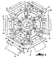
- the housing of apparatus 12 broadly designated by the numeral 42 (see Figs. 2-6, inclusive and particularly Fig. 3) includes a central flanged coupling 44 having a central cavity 46 which telescopically receives the upright output shaft 32 of gear unit 30.
- the normally uppermost end of cavity 46 is enlarged to present a shoulder 46a which receives a cap member 48 located to directly overlie the upper end of output shaft 32.
- Cap screws 50 passing through cap member 48 and threaded into the upper end of output shaft 32 serve to rigidly affixed housing 42 to the shaft 32 of gear unit 30.
- the outwardly directed, circular, peripheral flange portion 44a of coupling 44 is joined to a cylindrical, wall defining housing element 52 by a series of studs 54 passing through the lower annular rim 56 of element 52 into the periphery of flange 44a.
- Element 52 has six integral, radially directed tubular extensions which serve as bore defining sockets for receiving corresponding blade axle sections 60.
- a circular cover plate 62 closes the upper end of housing element 52 and is secured to the latter by a series of studs 64 extending through the perimeter of plate 62 and threaded into the upper wall segment of housing element 52.
- annular hub member 66 surrounds coupling 44 and is in slidable engagement with the outer cylindrical face of sleeve 68 overlying and supported by the cylindrical main body portion of coupling 44.
- the inner face 70 of hub member 66 has a pair of vertically-spaced, circumferentially extending grooves 72 therein which receive respective 0-ring seals 74.
- hub member 66 In order to reduce the mass of hub member 66, it preferably is constructed in a fashion to define an annular, inverted groove 73 coaxial with the inner face 70 of the hub.
- An annular, flexible diaphragm 76 is positioned on the top of hub member 66 and is secured by fastening means 78 to the inner circumference of the top face of hub member 66, as well as to the housing element 52 between the upper surface of the latter and the outer perimeter of circular plate 62.
- Fitting 80 (Figs. 2, 3, 5 and 6) mounted on the upper face of plate 62 and provided with an L-shaped passage 82 therein mounts a rotary coupling 84 in fluid communication with passage 82.
- Conduit 86 (Figs. 2, 5 and 6) serves to intercommunicate the interior of housing 42 and fluid coupling 84 by virtue of the fact that conduit 86 is joined to a nipple 88 threaded into an aperture 90 in the top plate 62.
- Conduit 86 is also joined to a nipple 93 threaded into the horizontal portion of passage 82 of fitting 80.
- a flexible hose 92 leads to a suitable source of pressurized fluid such as air under the control of sensing mechanism which is responsive to water temperature, process conditions or other parameters that are monitored for the purpose of varying the pitch of fan apparatus 12 accordingly.
- variable pitch blade and hub assembly making up apparatus 12 has six individual, radially extending blade units 94.
- Each of the units 94 has an axle section 60 as previously described which is telescoped in a corresponding cylindrical extension 58 of housing 52 and mounted for rotation therein by an inner ball bearing assembly 96 and an outer needle bearing assembly 98.
- Crank arm 100 bolted to the innermost face of each of the axle sections 60 through the medium of a series of studs 102 has an arm extension 104 which mounts a cam follower 106 on the outer extremity thereof.
- the outer wall section 66a of hub member 66 is provided with an outwardly facing inwardly directed circular cam groove 108 therein which receives the cam followers 106 of each of the crank arms 100.
- a series of bolts 118 extending through flanges 116 of blades 114 and threaded into respective flange portions 110a of mounting cups 110 serve to securely affix blades 114 to corresponding axle sections 60 as the blades telescope over and complementally engage the exterior surfaces of the mounting cups 110.
- Means for limiting the extent of rotation of axle sections 60 and thereby blades 114 takes the form of two pairs of adjustable limit devices 113 and 115 respectively located 180° apart from one another as best shown in Figs. 2, 4 and 5-8.
- a pair of devices 113 and 115 are associated with corresponding directly opposed mounting cups 110 of oppositely directed fan blades as best shown in Fig. 2.
- Each of the devices 113 and 115 includes an internally threaded projection 117 secured to the inner face of a corresponding flange 110a of a respective mounting cup 110. Screws 119 threaded into each projection 117 have lock nuts 121 thereon which jam against a proximal projection 117. Screws 119 of each pair of devices 113 and 115 engage opposite sides of corresponding bosses 123 (Figs. 4 and 5) projecting outwardly from housing 52 and also located in 180° spaced apart relationship around the perimeter of such housing.
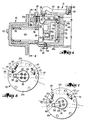
- crank arm 100 associated with one of the pairs of adjustable devices 113 and 115 is illustrated.
- the left device 115 controls shifting of the hub member 66 upwardly; the opposed right hand device 113 controls downward shifting of the hub member 66.
- the devices 113 limit the minimum pitch angle of the fan blades while devices 115 function to limit the maximum pitch angle of such blades.
- blades 114 may be fabricated of various types of material, a preferred embodiment of the invention utilizes hollow blades which are constructed of glass fiber reinforced synthetic resin material. Such construction allows fabrication of blades of the most desirable aerodynamic configuration having requisite compounds curves of different angularity along the longitudinal length of respective blades. Furthermore, such blades are of less weight than if fabricated out of metal to give a corresponding strength to weight ratio. Furthermore, the synthetic resin blades resist corrosion and deterioration in the relatively hostile environment that is present in the hot air discharge section of tower 10.
- tower 10 is provided with an air discharge stack or cylinder 120 which has an eased air inlet section 122 communicating directly with the plenum chamber 26 of the cooling tower 10.
- Blades 114 are of a length to terminate in relatively close proximity to the interior surface of the cylinder 120.
- FIG. 2 it is to be seen that six cantilever mounted straps 124 are secured on the upper surface of hub member 66 in equidistant spaced relationship and projecting radially from the axis thereof, with bolts 126 extending through corresponding straps 124 and threaded into the upper face of hub member 66 functioning to securely affix the straps 124 to hub member 66.
- Upright guide posts 128 affixed to the element 52 adjacent the upright wall thereof, aligned with corresponding straps 124 and received within suitable apertures 130 in straps 124, are telescoped within respective coil springs 132 trapped between each of the straps 124 and a proximal floor section of housing 52.
- Springs 132 are of a length to provide a bias force against hub member 66 of a magnitude to normally maintain the hub 66 in the normally uppermost position of the same depicted in Figs. 3 and 6.
- Hollow pin 134 extending through flange 44a of coupling 44 and the rim 56 of cylindrical housing element 52 (see Fig. 3) communicates the interior of housing 42 below diaphragm 76 with the surrounding atmosphere while preventing entrance of liquid by virtue of the relatively covered location of such pressure equalizing orifice.
- thermosensitive device 136 preferably located in the depressed central area of cold water basin 20 to monitor the temperature of the cold water leaving the tower 10.
- the output signals from such thermosensitive device are used to control a source of pressurized fluid such as air to housing 42 via line 92.
- gear unit 30 is driven via coupling 40 to thereby rotate shaft 32 and the hub and fan assembly apparatus 12 mounted thereon.
- Fan blades 114 are driven in a direction to cause ambient air to be drawn into the interior of tower 10 via opposed inlets whereby the air flows in crossflow relationship to hot water gravitating onto respective fills from hot water distribution basins 18 at opposite ends of the tower. Water which has been cooled by the crossflow air currents is collected in basins 20 for return to the process or condensing equipment or the like. Air is discharged from the plenum chamber 26 through the cylinder 120 which functions to limit recirculation of hot air back into the tower.
- crank arms 100 in this mode of operation is illustrated in Fig. 7 with control fluid under pressure within hub chamber 138 above diaphragm 76 and below cover plate 62.
- the pressurized fluid is directed from the source thereof via line 92, rotary coupling 84, fitting 80, and conduit 86 to the interior of housing 42.
- the fluid under pressure forces the hub member 66 downwardly against the bias of coil springs 132 into the disposition illustrated in Fig. 5 as limited by respective devices 113 thus causing the cam followers 106 located in groove 108 to be at their lower positions for minimum blade pitch.
- FIG. 8 The coarsest pitch position of blades 114 is depicted in Fig. 8 wherein it can be seen that the cam followers 106 riding in groove 108 have reached the uppermost end of their path of travel and crank arms 100 have been rotated through an arcuate displacement reflecting shifting of hub member 66 to the uppermost end of its path of travel as illustrated in Fig. 6 as controlled by the devices 115. It is apparent that as pressurized control fluid is delivered to chamber 138 or released therefrom, hub member 66 will descend or move upwardly as the case may be thereby simultaneously rotating crank arms 100 and thereby blades 114 rigidly affixed thereto, in direct response to the fluid pressure within chamber 138. Displacement of hub member 66 from the normally uppermost position thereof against cover plate 62 as shown in Fig. 6 toward the lowermost position of the same as shown in Fig. 5 does not cause a buildup of pressure within the lower part of housing 42 by virtue of the hollow pin 134 communicating the lower part of the hub with the surrounding atmosphere.
- the hub apparatus is permitted to freely rotate with respect to the pressurized fluid supply line 92 by virtue of the provision of rotary coupling 80 therebetween.
- apparatus 12 which is attributable not only to the way in which shaft 32 of gear unit 30 is telescopically received within hub member 66, but also because of the provision of relatively short coil springs 132 which surround the hub member 66, bear against straps 124, and serve to impose evenly distributed bias forces in an upward direction on the hub member 66 against fluid pressure within cavity 138 of housing 42.
- Another feature of the present invention is the fact that the components are well shielded against corrosion, the parts lend themselves to relatively easy disassembly and assembly for maintenance purposes, and the hub assembly apparatus may be employed as direct replacement for a non-variable pitch fan hub since the fan elevation of both units is the same. No change in the height of the fan cylinder is necessary.
Landscapes
- Engineering & Computer Science (AREA)
- Mechanical Engineering (AREA)
- General Engineering & Computer Science (AREA)
- Structures Of Non-Positive Displacement Pumps (AREA)
Applications Claiming Priority (2)
| Application Number | Priority Date | Filing Date | Title |
|---|---|---|---|
| US06/633,099 US4619586A (en) | 1984-07-19 | 1984-07-19 | Externally controlled variable pitch fan hub assembly |
| US633099 | 1984-07-19 |
Publications (2)
| Publication Number | Publication Date |
|---|---|
| EP0168710A2 true EP0168710A2 (fr) | 1986-01-22 |
| EP0168710A3 EP0168710A3 (fr) | 1987-05-06 |
Family
ID=24538277
Family Applications (1)
| Application Number | Title | Priority Date | Filing Date |
|---|---|---|---|
| EP85108158A Withdrawn EP0168710A3 (fr) | 1984-07-19 | 1985-07-01 | Ensemble de moyeu de ventilateur avec aubes à pas variable contrôlé de l'extérieur |
Country Status (3)
| Country | Link |
|---|---|
| US (1) | US4619586A (fr) |
| EP (1) | EP0168710A3 (fr) |
| JP (1) | JPS6158999A (fr) |
Families Citing this family (14)
| Publication number | Priority date | Publication date | Assignee | Title |
|---|---|---|---|---|
| US4664964A (en) * | 1984-04-23 | 1987-05-12 | Fuji Photo Film Co., Ltd. | Magnetic recording medium |
| DK155847C (da) * | 1987-04-10 | 1989-10-02 | Novenco As | Skovlvinkelreguleringsindretning til en aksialventilator med under drift indstillelige skovle |
| DK155848C (da) * | 1987-04-10 | 1989-10-02 | Novenco As | Aksialventilatorhjul |
| US6109871A (en) * | 1997-03-31 | 2000-08-29 | Horton, Inc. | Integrated fan assembly with variable pitch blades |
| DE19840843B4 (de) * | 1998-09-07 | 2013-11-21 | Hägele GmbH | Stellvorrichtung für ein im Kühlsystem von Brennkraftmaschinen einsetzbares Lüfterrad |
| EP0945626B1 (fr) * | 1998-03-26 | 2004-12-08 | Hägele GmbH | Ventilateur en particulier pour un système de refroidissement des machines à combustion |
| US6253716B1 (en) | 1999-07-07 | 2001-07-03 | Horton, Inc. | Control system for cooling fan assembly having variable pitch blades |
| US6443714B1 (en) | 1999-12-27 | 2002-09-03 | General Electric Company | Methods and apparatus for preventing moisture in fan motor housings |
| US6592328B1 (en) | 2001-04-17 | 2003-07-15 | Emerson Electric Co. | Method and apparatus for adjusting the pitch of a fan blade |
| CA2483109C (fr) | 2003-10-20 | 2012-05-01 | Flexxaire Manufacturing Inc. | Systeme de commande de ventilateur a pas variable |
| JP3717509B1 (ja) * | 2004-11-02 | 2005-11-16 | 俊孝 田中 | 気流拡散装置(拡散扇)及び空気調和機 |
| US20110105288A1 (en) * | 2006-04-04 | 2011-05-05 | Tony Susnjara | Exercise device |
| ES2362936T3 (es) * | 2006-04-04 | 2011-07-15 | Tony Susnjara | Dispositivo para realizar ejercicios. |
| CN109578339B (zh) * | 2019-01-24 | 2023-08-11 | 中国科学院工程热物理研究所 | 一种双自由度可调半高叶片扩压器装置 |
Family Cites Families (18)
| Publication number | Priority date | Publication date | Assignee | Title |
|---|---|---|---|---|
| FR631413A (fr) * | 1926-03-31 | 1927-12-20 | Anciens Ets Skoda | Aubes tournantes pour roues motrices |
| US2054810A (en) * | 1933-12-16 | 1936-09-22 | Gaba Achille Ernest | Adjustable pitch propeller |
| US2316940A (en) * | 1942-02-02 | 1943-04-20 | Fluor Corp | Blower control for mechanical draft cooling towers |
| US2392341A (en) * | 1942-09-10 | 1946-01-08 | William W Squier | Variable pitch propeller |
| FR995534A (fr) * | 1945-03-21 | 1951-12-04 | Hélice à pas variable | |
| FR1091979A (fr) * | 1953-01-31 | 1955-04-18 | Luwa Ag | Ventilateur à pales réglables |
| US2826395A (en) * | 1954-07-19 | 1958-03-11 | Hudson Engineering Corp | Atmospheric heat exchange apparatus and fan therefor |
| GB1023824A (en) * | 1961-12-07 | 1966-03-23 | Aerex Ltd | Improvements in and relating to variable or adjustable pitch fans |
| GB1011419A (en) * | 1963-02-07 | 1965-12-01 | Colchester Woods | Axial flow fans |
| US3935625A (en) * | 1971-03-30 | 1976-02-03 | Aktiebolaget Svenska Flaktfabriken | Method of manufacturing axial fans of different sizes |
| GB1372962A (en) * | 1973-01-12 | 1974-11-06 | Colchester Woods | Controllable pitch axial flow fans |
| US3967916A (en) * | 1973-06-11 | 1976-07-06 | Chittom Charles N | Fan assembly |
| US4019792A (en) * | 1976-04-29 | 1977-04-26 | Hudson Products Corporation | Bearing assembly |
| US4221541A (en) * | 1977-02-28 | 1980-09-09 | Axial International Aktiengesellschaft | Fan comprising a blade pitch control mechanism |
| SU641169A1 (ru) * | 1977-04-08 | 1979-01-05 | Предприятие П/Я В-2320 | Рабочее колесо осевого вентил тора |
| SU729383A1 (ru) * | 1977-12-05 | 1980-04-25 | Коломенский Тепловозостроительный Завод Им. В.В.Куйбышева | Рабочее колесо осевого вентил тора |
| GB2051966A (en) * | 1979-05-22 | 1981-01-21 | Colchester Woods | Variable Pitch Axial Flow Fan Impeller |
| ZA793463B (en) * | 1979-05-22 | 1980-06-25 | Colchester Woods | Impeller for variable pitch axial flow fan |
-
1984
- 1984-07-19 US US06/633,099 patent/US4619586A/en not_active Expired - Fee Related
-
1985
- 1985-07-01 EP EP85108158A patent/EP0168710A3/fr not_active Withdrawn
- 1985-07-15 JP JP60155870A patent/JPS6158999A/ja active Pending
Also Published As
| Publication number | Publication date |
|---|---|
| JPS6158999A (ja) | 1986-03-26 |
| US4619586A (en) | 1986-10-28 |
| EP0168710A3 (fr) | 1987-05-06 |
Similar Documents
| Publication | Publication Date | Title |
|---|---|---|
| US4619586A (en) | Externally controlled variable pitch fan hub assembly | |
| US7404525B2 (en) | Nozzle base clutch | |
| US6533010B1 (en) | Air regulating system for wheels | |
| US3117724A (en) | Moving sprinkler head | |
| US4783004A (en) | Ball drive sprinkler | |
| US20090272519A1 (en) | Gas lift plunger assembly arrangement | |
| US4687139A (en) | Ball drive sprinkler | |
| WO1987001620A1 (fr) | Tete d'arrosage rotative | |
| JPH02140496A (ja) | 変動ピッチファン | |
| US2316940A (en) | Blower control for mechanical draft cooling towers | |
| EP0772021A3 (fr) | Tours de refroidissement | |
| US3533607A (en) | Cooling tower with new liquid distribution and draft inducing means | |
| CA1151974A (fr) | Robinet a manchon deformable et ouverture reglable | |
| CN217898061U (zh) | 发电机组轴承油槽智能在线监测系统 | |
| CN2564245Y (zh) | 一种可自动温控的超重力反应器 | |
| CN220291796U (zh) | 一种具有堵塞告警功能的变频电机 | |
| NL8700856A (nl) | Sproeimachine, hoofdzakelijk voor verspreiding van een sproei-oplossing evenredig aan het oppervlak. | |
| CN115288911A (zh) | 发电机组轴承油槽智能在线监测系统及方法 | |
| US3703339A (en) | Turbine speed control system | |
| CN220646818U (zh) | 一种流体流量调节装置 | |
| US2072752A (en) | Power plant | |
| AU647828B2 (en) | Apparatus for treatment of vegetation | |
| CN223839774U (zh) | 一种带实时监测的流量可调高精度耐磨计量阀 | |
| CN213420055U (zh) | 一种电动调节阀 | |
| CN110657373A (zh) | 一种具有散热结构的led灯及散热控制系统和方法 |
Legal Events
| Date | Code | Title | Description |
|---|---|---|---|
| PUAI | Public reference made under article 153(3) epc to a published international application that has entered the european phase |
Free format text: ORIGINAL CODE: 0009012 |
|
| AK | Designated contracting states |
Designated state(s): BE DE FR GB IT |
|
| PUAL | Search report despatched |
Free format text: ORIGINAL CODE: 0009013 |
|
| AK | Designated contracting states |
Kind code of ref document: A3 Designated state(s): BE DE FR GB IT |
|
| STAA | Information on the status of an ep patent application or granted ep patent |
Free format text: STATUS: THE APPLICATION IS DEEMED TO BE WITHDRAWN |
|
| 18D | Application deemed to be withdrawn |
Effective date: 19871107 |
|
| RIN1 | Information on inventor provided before grant (corrected) |
Inventor name: CARTER, WILLIAM C. |