EP0169764A1 - Verfahren zur Herstellung von Waschrohren, insbesondere für Waschmaschinen - Google Patents
Verfahren zur Herstellung von Waschrohren, insbesondere für Waschmaschinen Download PDFInfo
- Publication number
- EP0169764A1 EP0169764A1 EP85401283A EP85401283A EP0169764A1 EP 0169764 A1 EP0169764 A1 EP 0169764A1 EP 85401283 A EP85401283 A EP 85401283A EP 85401283 A EP85401283 A EP 85401283A EP 0169764 A1 EP0169764 A1 EP 0169764A1
- Authority
- EP
- European Patent Office
- Prior art keywords
- chamfer
- tube
- bevel
- angle
- opposite
- Prior art date
- Legal status (The legal status is an assumption and is not a legal conclusion. Google has not performed a legal analysis and makes no representation as to the accuracy of the status listed.)
- Pending
Links
Images

Classifications
-
- A—HUMAN NECESSITIES
- A47—FURNITURE; DOMESTIC ARTICLES OR APPLIANCES; COFFEE MILLS; SPICE MILLS; SUCTION CLEANERS IN GENERAL
- A47L—DOMESTIC WASHING OR CLEANING; SUCTION CLEANERS IN GENERAL
- A47L15/00—Washing or rinsing machines for crockery or tableware
- A47L15/42—Details
-
- B—PERFORMING OPERATIONS; TRANSPORTING
- B05—SPRAYING OR ATOMISING IN GENERAL; APPLYING FLUENT MATERIALS TO SURFACES, IN GENERAL
- B05B—SPRAYING APPARATUS; ATOMISING APPARATUS; NOZZLES
- B05B1/00—Nozzles, spray heads or other outlets, with or without auxiliary devices such as valves, heating means
- B05B1/14—Nozzles, spray heads or other outlets, with or without auxiliary devices such as valves, heating means with multiple outlet openings; with strainers in or outside the outlet opening
- B05B1/20—Perforated pipes or troughs, e.g. spray booms; Outlet elements therefor
-
- B—PERFORMING OPERATIONS; TRANSPORTING
- B21—MECHANICAL METAL-WORKING WITHOUT ESSENTIALLY REMOVING MATERIAL; PUNCHING METAL
- B21D—WORKING OR PROCESSING OF SHEET METAL OR METAL TUBES, RODS OR PROFILES WITHOUT ESSENTIALLY REMOVING MATERIAL; PUNCHING METAL
- B21D28/00—Shaping by press-cutting; Perforating
- B21D28/24—Perforating, i.e. punching holes
- B21D28/28—Perforating, i.e. punching holes in tubes or other hollow bodies
Definitions
- the subject of the present invention is the manufacture of washing or spraying ramps, in particular for equipping all types of washing machines, these washing ramps being designed so as to solve all the problems of sprinkling, sprinkling , soaking, takeoff, and all similar problems.
- the washing ramp is produced in the form of a tube 10, which is drilled with cylindrical holes such as 12, which can be milled (12 ′, Fig. 2) on the 'outside.
- the holes 12 or 12 ' are drilled from the outside towards the inside of the tube.
- the watering boom is also in the form of a tube 10 having holes in which are screwed sprayers or spray nozzles 14, which may have different shapes depending on the desired applications .
- the present invention proposes to provide a method of manufacturing washing or dispersion ramps which does not have the drawbacks of known solutions.
- the invention relates to washing or spraying ramps of variable length, comprising one or more jets, these ramps being intended to equip any type of washing machine, and more particularly washing machines for industrial equipment, and to resolve the problems with spraying, soaking and taking off, etc.
- the subject of this invention is a process for the manufacture of washing or spraying ramps, characterized in that it consists in starting from a tube which can be machined, in milling in the thickness of said tube a chamfer, the angle at the apex is between 25 and 60 °, at the point where it is desired to obtain a jet, to drill a hole in the wall opposite to that where said chamfer has been milled, then to machine, opposite said chamfer, a second chamfer with an angle at the apex of between 90 and 150 °, this second chamfer opening through the tube in the first chamfer, so as to produce an elliptical opening whose surface increases as the distance which separates the vertices of the angles of the first and second chamfer increases, the hole which is drilled in the wall opposite to said elliptical opening being filled, preferably by welding.
- the method according to the invention consists in starting from a tube which can be made of very diverse materials, such as, in particular: steel, stainless steel, copper, graphite, etc.
- the thickness of the tube is preferably equal to or greater than 4 mm.
- the method according to the present invention essentially comprises two steps:
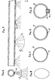
- a chamfer 18 is cut through the thickness of the tube 10, having an apex angle b whose value is between 25 and 60 °, and preferably equal to 45 °.
- the chamfer thus produced can be local and arranged opposite each jet, the length of the chamfer d (that is to say the dimension between the outer edge of the tube and the top of the angle b) making it possible to obtain the desired opening.
- the chamfer 18 can be produced over the entire thickness of the tube, without departing from the scope of the present invention, this variant not causing any modification in the efficiency of the jets finally obtained.
- the apex angle a of the same bisector as the angle b, has a value between 90 and 150 °, and preferably equal to 120 °.
- an opening is thus produced which is obtained by the meeting of the chamfers 18 and 20, this opening having the shape of an ellipse 24 (FIG. 5), the surface of which increases as the distance between the vertices of angles a and b. in Figure 4, this distance is represented by the difference between dimension d and dimension c.
- the diameter e which corresponds to the diameter of the hole 22, varies as a function of the diameter and the thickness of the tube, in order to obtain the dimension h, that is to say the length of the cylindrical part on which the chamfer 20 opens.
- the references f and g designate respectively the width and the length of the ellipse 24.
- the hole 22 is filled in, preferably by welding, in order to avoid attachment points.
- Figures 6 to 8 show the shape of the elliptical jets obtained using a ramp produced according to the method of the invention.
Landscapes
- Engineering & Computer Science (AREA)
- Mechanical Engineering (AREA)
- Nozzles (AREA)
- Cleaning By Liquid Or Steam (AREA)
Applications Claiming Priority (2)
| Application Number | Priority Date | Filing Date | Title |
|---|---|---|---|
| FR8411232A FR2567422B1 (fr) | 1984-07-16 | 1984-07-16 | Procede de fabrication de rampes de lavage, notamment pour machines a laver |
| FR8411232 | 1984-07-16 |
Publications (1)
| Publication Number | Publication Date |
|---|---|
| EP0169764A1 true EP0169764A1 (de) | 1986-01-29 |
Family
ID=9306150
Family Applications (1)
| Application Number | Title | Priority Date | Filing Date |
|---|---|---|---|
| EP85401283A Pending EP0169764A1 (de) | 1984-07-16 | 1985-06-25 | Verfahren zur Herstellung von Waschrohren, insbesondere für Waschmaschinen |
Country Status (2)
| Country | Link |
|---|---|
| EP (1) | EP0169764A1 (de) |
| FR (1) | FR2567422B1 (de) |
Cited By (3)
| Publication number | Priority date | Publication date | Assignee | Title |
|---|---|---|---|---|
| DE102005015156A1 (de) * | 2005-04-02 | 2006-10-05 | Premark Feg L.L.C., Wilmington | Transportgeschirrspülmaschine und Sprührohr dafür |
| WO2007097714A1 (en) * | 2006-02-24 | 2007-08-30 | Kim Lui So | Method and apparatus for supplying a fluid |
| EP2154350A4 (de) * | 2007-05-28 | 2011-06-01 | Mitsubishi Heavy Ind Ltd | Verfahren zur erzeugung durchgehender löcher in den wandoberflächen von rohrelementen und rohrelementstruktur |
Families Citing this family (1)
| Publication number | Priority date | Publication date | Assignee | Title |
|---|---|---|---|---|
| CN104889697A (zh) * | 2015-06-19 | 2015-09-09 | 江西洪都航空工业集团有限责任公司 | 一种液体喷射方向引导结构 |
Citations (6)
| Publication number | Priority date | Publication date | Assignee | Title |
|---|---|---|---|---|
| US2641509A (en) * | 1948-04-27 | 1953-06-09 | Clyde E Yost | Spray nozzle |
| US2665946A (en) * | 1951-05-29 | 1954-01-12 | Arthur E Broughton | Spray nozzle |
| DE1182785B (de) * | 1962-05-23 | 1964-12-03 | Linde Eismasch Ag | Spuelmaschine, insbesondere fuer Geschirr |
| DE1302680B (de) * | 1963-07-18 | 1970-11-26 | ||
| DE2806936A1 (de) * | 1977-02-18 | 1978-08-24 | Cera Int Ltd | Spruehvorrichtung fuer industrielle waschmaschinen |
| GB2093372A (en) * | 1981-02-19 | 1982-09-02 | Albany Int Corp | Fan spray nozzle |
-
1984
- 1984-07-16 FR FR8411232A patent/FR2567422B1/fr not_active Expired
-
1985
- 1985-06-25 EP EP85401283A patent/EP0169764A1/de active Pending
Patent Citations (6)
| Publication number | Priority date | Publication date | Assignee | Title |
|---|---|---|---|---|
| US2641509A (en) * | 1948-04-27 | 1953-06-09 | Clyde E Yost | Spray nozzle |
| US2665946A (en) * | 1951-05-29 | 1954-01-12 | Arthur E Broughton | Spray nozzle |
| DE1182785B (de) * | 1962-05-23 | 1964-12-03 | Linde Eismasch Ag | Spuelmaschine, insbesondere fuer Geschirr |
| DE1302680B (de) * | 1963-07-18 | 1970-11-26 | ||
| DE2806936A1 (de) * | 1977-02-18 | 1978-08-24 | Cera Int Ltd | Spruehvorrichtung fuer industrielle waschmaschinen |
| GB2093372A (en) * | 1981-02-19 | 1982-09-02 | Albany Int Corp | Fan spray nozzle |
Cited By (7)
| Publication number | Priority date | Publication date | Assignee | Title |
|---|---|---|---|---|
| DE102005015156A1 (de) * | 2005-04-02 | 2006-10-05 | Premark Feg L.L.C., Wilmington | Transportgeschirrspülmaschine und Sprührohr dafür |
| US7621286B2 (en) | 2005-04-02 | 2009-11-24 | Premark Feg L.L.C. | Conveyor ware washer and spray pipe therefor |
| WO2007097714A1 (en) * | 2006-02-24 | 2007-08-30 | Kim Lui So | Method and apparatus for supplying a fluid |
| AU2007218219B2 (en) * | 2006-02-24 | 2011-03-31 | Kim Lui So | Method and apparatus for supplying a fluid |
| US8066201B2 (en) | 2006-02-24 | 2011-11-29 | Kim Lui So | Method and apparatus for supplying a fluid |
| EP2154350A4 (de) * | 2007-05-28 | 2011-06-01 | Mitsubishi Heavy Ind Ltd | Verfahren zur erzeugung durchgehender löcher in den wandoberflächen von rohrelementen und rohrelementstruktur |
| US8776369B2 (en) | 2007-05-28 | 2014-07-15 | Mitsubishi Heavy Industries, Ltd. | Through-hole manufacturing method for cylindrical body wall and cylindrical body structure |
Also Published As
| Publication number | Publication date |
|---|---|
| FR2567422B1 (fr) | 1987-05-15 |
| FR2567422A1 (fr) | 1986-01-17 |
Similar Documents
| Publication | Publication Date | Title |
|---|---|---|
| EP0027252B1 (de) | Vorrichtung zum Herstellen von Körpern wabenförmiger Struktur durch Extrusion eines keramischen Materials und Verfahren zur Herstellung dieser Vorrichtung | |
| EP0108666B1 (de) | Vorrichtung zum Erodieren einer festen Oberfläche mittels einer hohlraumbildenden Strömung | |
| EP0656239B1 (de) | Verfahren zum Bearbeiten von Werkstücken aus Titan oder Titanlegierungen sowie Sprühklemme dazu | |
| EP1608498B1 (de) | Verfahren zur herstellung eines abluftsystems in einem behälter mit mehreren wänden | |
| EP0225262B1 (de) | Formgebung von schraubenförmigen Gewinden mit Null- oder negativer Seiteninklination | |
| FR2635032A1 (fr) | Outil de coupe de metaux | |
| EP0169764A1 (de) | Verfahren zur Herstellung von Waschrohren, insbesondere für Waschmaschinen | |
| FR2485399A1 (fr) | Tuyere de pulverisation en cone plein | |
| FR2558558A1 (fr) | Bague d'etancheite pour arbre rotatif | |
| WO2020161266A1 (fr) | Bec de remplissage a depression | |
| EP0974533A1 (de) | Umkehrbarer Spender für Fluide | |
| FR2829715A1 (fr) | Foret de precision | |
| EP4230332A1 (de) | Schneidwerkzeug mit integrierter schmierung | |
| EP2362496A1 (de) | Verbindungselement Produktionsmethode für Bajonettverbinder und Verbindungsvorrichtung | |
| FR2481153A1 (fr) | Dispositif et procede pour la fabrication par etirage de tubes a parois irregulieres | |
| EP0251929B1 (de) | Verbindungsstück zwischen einem starren Element und einem Schlauch | |
| WO2020201215A1 (fr) | Buse pour système de pulvérisation et système de pulvérisation comprenant une telle buse | |
| EP3471882B1 (de) | Pipettiersystemspitze mit doppelter konizität | |
| EP0020246B1 (de) | Vorrichtung zum Kühlen langer laminierter Wärmwalzprodukte | |
| FR2552830A1 (fr) | Rivet aveugle a tete secondaire de grandes dimensions | |
| FR2572665A1 (fr) | Electrode-outil pour le percage par electroerosion, procede de percage par electroerosion au moyen de ladite electrode-outil et pieces percees conformement audit procede | |
| KR200337984Y1 (ko) | 안경렌즈의 부분 진공증착용 지그 | |
| EP0819858A1 (de) | Krimpmutter mit eingebettetem Kopf | |
| EP1914177A1 (de) | Verteilungsvorrichtung für ein flüssiges Produkt | |
| EP0187608A2 (de) | Schnellverbindung für unter Druck stehende Flüssigkeitssysteme in denen der Druck 150 bar erreichen kann |
Legal Events
| Date | Code | Title | Description |
|---|---|---|---|
| PUAI | Public reference made under article 153(3) epc to a published international application that has entered the european phase |
Free format text: ORIGINAL CODE: 0009012 |
|
| AK | Designated contracting states |
Kind code of ref document: A1 Designated state(s): AT BE CH DE GB IT LI LU NL SE |
|
| 17P | Request for examination filed |
Effective date: 19860925 |
|
| STAA | Information on the status of an ep patent application or granted ep patent |
Free format text: STATUS: EXAMINATION IS IN PROGRESS |
|
| 17Q | First examination report despatched |
Effective date: 19880705 |
|
| RAP3 | Party data changed (applicant data changed or rights of an application transferred) |
Owner name: LE GUEN, ANNICK, EPOUSE MOUTARDE Owner name: MOUTARDE, JOSEPH |
|
| RAP3 | Party data changed (applicant data changed or rights of an application transferred) |
Owner name: LE GUEN, ANNICK, EPOUSE MOUTARDE Owner name: MOUTARDE, JOSEPH |