EP0169944B1 - Ventilverteiler, insbesondere für mehrere Heizungskreise - Google Patents
Ventilverteiler, insbesondere für mehrere Heizungskreise Download PDFInfo
- Publication number
- EP0169944B1 EP0169944B1 EP84116377A EP84116377A EP0169944B1 EP 0169944 B1 EP0169944 B1 EP 0169944B1 EP 84116377 A EP84116377 A EP 84116377A EP 84116377 A EP84116377 A EP 84116377A EP 0169944 B1 EP0169944 B1 EP 0169944B1
- Authority
- EP
- European Patent Office
- Prior art keywords
- valve
- manifold
- seat
- shutter
- threaded
- Prior art date
- Legal status (The legal status is an assumption and is not a legal conclusion. Google has not performed a legal analysis and makes no representation as to the accuracy of the status listed.)
- Expired
Links
Images
Classifications
-
- F—MECHANICAL ENGINEERING; LIGHTING; HEATING; WEAPONS; BLASTING
- F24—HEATING; RANGES; VENTILATING
- F24D—DOMESTIC- OR SPACE-HEATING SYSTEMS, e.g. CENTRAL HEATING SYSTEMS; DOMESTIC HOT-WATER SUPPLY SYSTEMS; ELEMENTS OR COMPONENTS THEREFOR
- F24D19/00—Details
- F24D19/0002—Means for connecting central heating radiators to circulation pipes
-
- F—MECHANICAL ENGINEERING; LIGHTING; HEATING; WEAPONS; BLASTING
- F16—ENGINEERING ELEMENTS AND UNITS; GENERAL MEASURES FOR PRODUCING AND MAINTAINING EFFECTIVE FUNCTIONING OF MACHINES OR INSTALLATIONS; THERMAL INSULATION IN GENERAL
- F16L—PIPES; JOINTS OR FITTINGS FOR PIPES; SUPPORTS FOR PIPES, CABLES OR PROTECTIVE TUBING; MEANS FOR THERMAL INSULATION IN GENERAL
- F16L41/00—Branching pipes; Joining pipes to walls
- F16L41/08—Joining pipes to walls or pipes, the joined pipe axis being perpendicular to the plane of a wall or to the axis of another pipe
- F16L41/16—Joining pipes to walls or pipes, the joined pipe axis being perpendicular to the plane of a wall or to the axis of another pipe the branch pipe comprising fluid cut-off means
-
- F—MECHANICAL ENGINEERING; LIGHTING; HEATING; WEAPONS; BLASTING
- F24—HEATING; RANGES; VENTILATING
- F24D—DOMESTIC- OR SPACE-HEATING SYSTEMS, e.g. CENTRAL HEATING SYSTEMS; DOMESTIC HOT-WATER SUPPLY SYSTEMS; ELEMENTS OR COMPONENTS THEREFOR
- F24D19/00—Details
- F24D19/0002—Means for connecting central heating radiators to circulation pipes
- F24D19/0026—Places of the inlet on the radiator
Definitions
- the present invention relates to a manifold valve particularly for multiple circuit heating systems.
- the delivery and return ends of the individual circuits are connected to known delivery and return manifolds.
- delivery and return manifolds For the purpose of providing an improved regulation of the hot water flow through radiators, also known is to associate automatic and shutter valves with said manifolds.
- Automatic valves are provided on the return manifold, and shutter valves are provided on the delivery or intake manifolds.
- the automatic valves may have any configurations which may suit automatic control, such as through an electric control, space thermostat, and the like.
- Prior embodiments of such automatic and shutter valves are of two-part construction, namely one part accommodating the valve or valve shutter, and another part forming the cut-off seat, said two parts being threaded into respective seats in the fitting at diametrically opposed and aligned locations.
- the two parts of the valve In order for such valves or shutter valves to operate properly, or to achieve a reliable closure in the cut-off position, or position of engagement of the valve or shutter valve moving body with the cut-off seat, the two parts of the valve must be mounted truly coaxial with each other.
- the manifold outer surfaces moreover, must be precision machined since they form sealing surfaces. Providing two separate valve parts, mounting them in perfect coaxial relationship, and forming the sealing surfaces on the manifold involve expensive construction and assembling procedure.
- each manifold is to be provided with a high number of branch connections for such circuits, e.g. on the order of 5-10 circuits.
- the two intake and discharge manifolds for such circuits require 20 to 40 coaxial seats, and attendant outer surface finishing, any faulty machining of one or more of such seats jeopardizing the manifold effectiveness.
- Another disadvantage of the prior embodiments is that assembling the two valve parts requires two threaded connections for each valve as well as several intermediate connection components. Besides being expensive to manufacture, all this involves long assembly times.
- the document FR-A-2,314,452 discloses an heating radiator including a throughgoing regulating valve with a cartridge case.
- the ends of the valve case have no coupling portions.
- the case ends are houses with clearance in throughgoing seats of the radiator and are fixed therein by welding. Therefore said valves are not fit for being used in manifolds for multiple circuit heating systems.
- This invention is directed to provide a manifold valve of the general type indicated herein above, which affords faultless coaxial movement of the moving valve part relatively to the cut-off seat, is of simple construction with a limited number of components, and can speed up assembling without involving any special machining of the manifold outer surfaces.
- valve of this invention brings about simpler machining of its supporting seats on the manifold.
- valve shutter can be positioned at its selected position.
- valve housing arranged to extend through the manifold body and provided at its ends with coupling portions for engagement with corresponding seats formed in said manifold, said coupling portions being provided with a sealing means and said valve housing accommodating a valve shutter movable axially therein and cooperating with the internal sealing seat of said valve housing, whereby said valve housing is provided downstream of the sealing seat with passage windows for the fluid to be regulated and whereby an integral positioning means is provided for said shutter, the aim of this invention is achieved by a valve characterised in that:
- the proposed manifold valve affords both functional and constructional and assembling advantages.
- valve housing being a single-piece construction and involving no problems of coaxial alignment of the movable part to the stationary seat.
- Construction- wise a single threaded coupling is provided between the manifold and valve, or the housing thereof, whilst to the other coupling is accomplished by means of an easily manufactured cylindrical coupling.
- the fitting for the associated circuit pipe is formed directly in the valve housing.
- the bores for the manifold seats are made with a simple boring operation. Sealing by means of O-rings is faultless and the seats for the latter can be machined in a simple conventional manner.
- the fluid passage ports are simply obtained by slotting. As brought out by practical tests, the valve housing practically does not alter the flow ratios.
- An additional advantage is that a means of locking the shutter at a desired position is provided, as well as a means effective to prevent the shutter from coming out.
- the proposed valve also facilitated is storage, in that the valve components are fewer in number, that is, fewer are the components required to assemble the valve and the fittings for connection to the piping of the associated heating circuits.
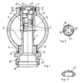
- a manifold valve according to the invention is generally indicated at 1.
- the same includes a full-diameter valve housing 2 with a shutter 3.
- the valve housing 2 is formed internally with a sealing seat 4 with which the shutter 3 cooperates.
- the valve housings 2 are fitted continuously through the manifold bodies, indicated at 5.
- coupling portions 6 and 7 for engagement with corresponding seats 8 and 9 formed in the manifold body 5.
- the seat 8 in the manifold is a threaded seat, whereas the seat 9 is a cylindrical one.
- the portion 6 is also formed with an outside thread whereas the coupling portion 7 is a cylindrical portion.
- a seat 10 accommodating an O-ring seal 11
- the seat 8 is also formed with a seat 12 accommodating an O-ring seal 13.
- Indicated at 14 are slots or windows for the fluid passage from the piping of the heating circuit schematically represented in dash lines at 15, from the valve housing into the manifold 5.
- a threaded seat 16 adapted to receive the shutter 3.
- a locking and locating ring nut 17 formed with a driving slot 18.
- Indicated at 19 is a circular middle opening in the ring nut 17 for access by an Allen spanner to engage with the recessed hexagon 20 in the shutter 3.
- a collar 21 which, after the shutter 3 and ring nut 17 have been inserted into the inside threaded seat 16, is turned in and prevents said ring nuts, or shutter, from coming out.
- said turned-in collar 21 also acts as a retainer for a covering cap 22 ( Figure 3).
- threaded coupling portion 6 is extended to form a bearing collar 23, conveniently of hexagonal shape, and then form a threaded fitting 24 adapted to receive the return end of the piping 15 of the associated heating circuit. It is to be noted that it is not necessary to later machine the outside of the seat 8, because the seal is provided by the 0-ring seal 13.
- the latter For adjusting the shutter 3 for operation, the latter will be first positioned using the hexagon end of an Allen spanner, whereafter that position will be locked by engaging the driving slots 18 of the ring nut 17 by means of a screwdriver.
- the position of the shutter 3 can be changed at any time by removing the closure cap 22.
Landscapes
- Engineering & Computer Science (AREA)
- General Engineering & Computer Science (AREA)
- Mechanical Engineering (AREA)
- Physics & Mathematics (AREA)
- Thermal Sciences (AREA)
- Chemical & Material Sciences (AREA)
- Combustion & Propulsion (AREA)
- Valve Housings (AREA)
- Lift Valve (AREA)
- Details Of Valves (AREA)
- Multiple-Way Valves (AREA)
Claims (3)
ii. eine Sicherheitseinrichtung in Form eines Kragens (21), der an der Aussenseite des zylindrischen Abschnitts (7) des Ventilkoerpers (2) ausgebildet ist, wodurch dieser Kragen (21), nachdem der Ventilschliesser (3) und die Ringmutter (17) in den Sitz (16) dafuer eingesetzt sind, eingedreht wird.
Priority Applications (1)
| Application Number | Priority Date | Filing Date | Title |
|---|---|---|---|
| AT84116377T ATE41505T1 (de) | 1984-07-20 | 1984-12-27 | Ventilverteiler, insbesondere fuer mehrere heizungskreise. |
Applications Claiming Priority (2)
| Application Number | Priority Date | Filing Date | Title |
|---|---|---|---|
| IT21984/84A IT1176444B (it) | 1984-07-20 | 1984-07-20 | Valvola per collettori,in particolare per impianti di riscaldamento a piu' circuiti |
| IT2198484 | 1984-07-20 |
Publications (2)
| Publication Number | Publication Date |
|---|---|
| EP0169944A1 EP0169944A1 (de) | 1986-02-05 |
| EP0169944B1 true EP0169944B1 (de) | 1989-03-15 |
Family
ID=11189781
Family Applications (1)
| Application Number | Title | Priority Date | Filing Date |
|---|---|---|---|
| EP84116377A Expired EP0169944B1 (de) | 1984-07-20 | 1984-12-27 | Ventilverteiler, insbesondere für mehrere Heizungskreise |
Country Status (3)
| Country | Link |
|---|---|
| EP (1) | EP0169944B1 (de) |
| AT (1) | ATE41505T1 (de) |
| IT (1) | IT1176444B (de) |
Cited By (1)
| Publication number | Priority date | Publication date | Assignee | Title |
|---|---|---|---|---|
| DE102015207006A1 (de) | 2015-04-17 | 2016-10-20 | Volkswagen Aktiengesellschaft | Fahrzeugtürverriegelungssystem, Fahrzeugtür, Vorrichtung |
Families Citing this family (4)
| Publication number | Priority date | Publication date | Assignee | Title |
|---|---|---|---|---|
| FR2611849B1 (fr) * | 1987-02-26 | 1989-06-09 | Comap | Dispositif de reglage interchangeable pour robinet thermostatique |
| AT399025B (de) * | 1993-01-26 | 1995-03-27 | Herz Armaturen Ag | Heizkörperventil |
| CN1216246C (zh) * | 2000-03-20 | 2005-08-24 | 贾科米尼公开有限公司 | 用于供热和卫生系统的改进模块式歧管和改进的歧管模块 |
| ES1056756Y (es) * | 2004-02-16 | 2004-08-16 | Fagor S Coop | Sistema de amarre de un grifo de gas en una rampa. |
Citations (1)
| Publication number | Priority date | Publication date | Assignee | Title |
|---|---|---|---|---|
| DE7405314U (de) * | 1974-05-30 | Gebrueder Beul & Co | Hohlprofil zur Herstellung von Verteilereinrichtungen in Rohrleitungssystemen |
Family Cites Families (5)
| Publication number | Priority date | Publication date | Assignee | Title |
|---|---|---|---|---|
| FR1245801A (fr) * | 1958-11-18 | 1960-11-10 | Josef Hamacher Vdi Warme Luft | Chambre de distribution pour échangeurs de chaleur à admission réglable du fluide |
| FR1564870A (de) * | 1968-03-13 | 1969-04-25 | ||
| AT339000B (de) * | 1975-06-11 | 1977-09-26 | Wien Stadt | Plattenheizkorper |
| FR2415248A1 (fr) * | 1978-01-20 | 1979-08-17 | Robimatic Sa | Robinet d'ordonnance |
| DE3378844D1 (en) * | 1983-09-07 | 1989-02-09 | Harry Konig | Housing for fitting a thermostatic valve |
-
1984
- 1984-07-20 IT IT21984/84A patent/IT1176444B/it active
- 1984-12-27 EP EP84116377A patent/EP0169944B1/de not_active Expired
- 1984-12-27 AT AT84116377T patent/ATE41505T1/de not_active IP Right Cessation
Patent Citations (1)
| Publication number | Priority date | Publication date | Assignee | Title |
|---|---|---|---|---|
| DE7405314U (de) * | 1974-05-30 | Gebrueder Beul & Co | Hohlprofil zur Herstellung von Verteilereinrichtungen in Rohrleitungssystemen |
Cited By (1)
| Publication number | Priority date | Publication date | Assignee | Title |
|---|---|---|---|---|
| DE102015207006A1 (de) | 2015-04-17 | 2016-10-20 | Volkswagen Aktiengesellschaft | Fahrzeugtürverriegelungssystem, Fahrzeugtür, Vorrichtung |
Also Published As
| Publication number | Publication date |
|---|---|
| IT1176444B (it) | 1987-08-18 |
| EP0169944A1 (de) | 1986-02-05 |
| ATE41505T1 (de) | 1989-04-15 |
| IT8421984A1 (it) | 1986-01-20 |
| IT8421984A0 (it) | 1984-07-20 |
Similar Documents
| Publication | Publication Date | Title |
|---|---|---|
| CA2106963C (en) | Valve for flowing liquid-phase medium | |
| CA2170428C (en) | Ball valve with a strainer and integrated means for flushing the strainer | |
| US7644730B2 (en) | Method for isolating an appliance in a plumbing system | |
| US6007045A (en) | Membrane valve assembly | |
| US20070215215A1 (en) | Isolation valve with rotatable flange | |
| US8371332B2 (en) | Modular pressure balancing valve | |
| CA2113024A1 (en) | High Pressure Relief System | |
| US5520213A (en) | Valve assembly | |
| CA3117779C (en) | Tankless water heater isolation valve assembly | |
| US5906224A (en) | Reserve fuel valve and method for making | |
| GB2229521A (en) | Central heating radiators | |
| EP0169944A1 (de) | Ventilverteiler, insbesondere für mehrere Heizungskreise | |
| US20030020041A1 (en) | Back seating valve with service port | |
| EP1701072B1 (de) | Kugelhahnanordnung mit Rückschlagventil | |
| US20060006247A1 (en) | Thermostatic valve for a cooling circuit | |
| HUT70106A (en) | Joining fitting of heaters | |
| WO1996021819A1 (en) | Pressure balancing device | |
| EP3636969A1 (de) | Ventil | |
| US5720316A (en) | Sanitary fitting | |
| US4930540A (en) | Flow diverter for a vehicle heating system | |
| US12607392B2 (en) | Valve device for a heat-pump system, heat-pump-system having such a valve device, and building having such a valve device or such a heat-pump system | |
| US3659632A (en) | Faucet control having an auxiliary outlet | |
| US5007239A (en) | Master cylinder with sandwiched communication interfaces | |
| WO1996019690A1 (en) | Diaphragm-controlled valve | |
| ES8701341A3 (es) | Valvula para colectores,en particular para instalaciones de calefaccion de varios circuitos |
Legal Events
| Date | Code | Title | Description |
|---|---|---|---|
| PUAI | Public reference made under article 153(3) epc to a published international application that has entered the european phase |
Free format text: ORIGINAL CODE: 0009012 |
|
| AK | Designated contracting states |
Designated state(s): AT BE CH DE FR GB LI LU NL SE |
|
| 17P | Request for examination filed |
Effective date: 19860203 |
|
| 17Q | First examination report despatched |
Effective date: 19860624 |
|
| GRAA | (expected) grant |
Free format text: ORIGINAL CODE: 0009210 |
|
| AK | Designated contracting states |
Kind code of ref document: B1 Designated state(s): AT BE CH DE FR GB LI LU NL SE |
|
| REF | Corresponds to: |
Ref document number: 41505 Country of ref document: AT Date of ref document: 19890415 Kind code of ref document: T |
|
| REF | Corresponds to: |
Ref document number: 3477258 Country of ref document: DE Date of ref document: 19890420 |
|
| ET | Fr: translation filed | ||
| PGFP | Annual fee paid to national office [announced via postgrant information from national office to epo] |
Ref country code: GB Payment date: 19891130 Year of fee payment: 6 |
|
| PG25 | Lapsed in a contracting state [announced via postgrant information from national office to epo] |
Ref country code: LU Free format text: LAPSE BECAUSE OF NON-PAYMENT OF DUE FEES Effective date: 19891231 |
|
| PLBE | No opposition filed within time limit |
Free format text: ORIGINAL CODE: 0009261 |
|
| STAA | Information on the status of an ep patent application or granted ep patent |
Free format text: STATUS: NO OPPOSITION FILED WITHIN TIME LIMIT |
|
| 26N | No opposition filed | ||
| PGFP | Annual fee paid to national office [announced via postgrant information from national office to epo] |
Ref country code: SE Payment date: 19901207 Year of fee payment: 7 |
|
| PGFP | Annual fee paid to national office [announced via postgrant information from national office to epo] |
Ref country code: LU Payment date: 19901210 Year of fee payment: 7 |
|
| PG25 | Lapsed in a contracting state [announced via postgrant information from national office to epo] |
Ref country code: GB Effective date: 19901227 |
|
| EPTA | Lu: last paid annual fee | ||
| GBPC | Gb: european patent ceased through non-payment of renewal fee | ||
| PG25 | Lapsed in a contracting state [announced via postgrant information from national office to epo] |
Ref country code: SE Effective date: 19911228 |
|
| EUG | Se: european patent has lapsed |
Ref document number: 84116377.7 Effective date: 19920704 |
|
| PGFP | Annual fee paid to national office [announced via postgrant information from national office to epo] |
Ref country code: AT Payment date: 19971125 Year of fee payment: 14 |
|
| PGFP | Annual fee paid to national office [announced via postgrant information from national office to epo] |
Ref country code: FR Payment date: 19971215 Year of fee payment: 14 |
|
| PGFP | Annual fee paid to national office [announced via postgrant information from national office to epo] |
Ref country code: NL Payment date: 19971231 Year of fee payment: 14 |
|
| PGFP | Annual fee paid to national office [announced via postgrant information from national office to epo] |
Ref country code: BE Payment date: 19980107 Year of fee payment: 14 |
|
| PGFP | Annual fee paid to national office [announced via postgrant information from national office to epo] |
Ref country code: CH Payment date: 19980123 Year of fee payment: 14 |
|
| PGFP | Annual fee paid to national office [announced via postgrant information from national office to epo] |
Ref country code: DE Payment date: 19980204 Year of fee payment: 14 |
|
| PG25 | Lapsed in a contracting state [announced via postgrant information from national office to epo] |
Ref country code: AT Free format text: LAPSE BECAUSE OF NON-PAYMENT OF DUE FEES Effective date: 19981227 |
|
| PG25 | Lapsed in a contracting state [announced via postgrant information from national office to epo] |
Ref country code: LI Free format text: LAPSE BECAUSE OF NON-PAYMENT OF DUE FEES Effective date: 19981231 Ref country code: CH Free format text: LAPSE BECAUSE OF NON-PAYMENT OF DUE FEES Effective date: 19981231 Ref country code: BE Free format text: LAPSE BECAUSE OF NON-PAYMENT OF DUE FEES Effective date: 19981231 |
|
| BERE | Be: lapsed |
Owner name: RUBINETTERIE A. GIACOMINI S.P.A. Effective date: 19981231 |
|
| PG25 | Lapsed in a contracting state [announced via postgrant information from national office to epo] |
Ref country code: NL Free format text: LAPSE BECAUSE OF NON-PAYMENT OF DUE FEES Effective date: 19990701 |
|
| REG | Reference to a national code |
Ref country code: CH Ref legal event code: PL |
|
| PG25 | Lapsed in a contracting state [announced via postgrant information from national office to epo] |
Ref country code: FR Free format text: LAPSE BECAUSE OF NON-PAYMENT OF DUE FEES Effective date: 19990831 |
|
| NLV4 | Nl: lapsed or anulled due to non-payment of the annual fee |
Effective date: 19990701 |
|
| REG | Reference to a national code |
Ref country code: FR Ref legal event code: ST |
|
| PG25 | Lapsed in a contracting state [announced via postgrant information from national office to epo] |
Ref country code: DE Free format text: LAPSE BECAUSE OF NON-PAYMENT OF DUE FEES Effective date: 19991001 |