EP0170248A2 - Machine de soudage à l'arc par impulsions du type à électrode consommable - Google Patents
Machine de soudage à l'arc par impulsions du type à électrode consommable Download PDFInfo
- Publication number
- EP0170248A2 EP0170248A2 EP85109525A EP85109525A EP0170248A2 EP 0170248 A2 EP0170248 A2 EP 0170248A2 EP 85109525 A EP85109525 A EP 85109525A EP 85109525 A EP85109525 A EP 85109525A EP 0170248 A2 EP0170248 A2 EP 0170248A2
- Authority
- EP
- European Patent Office
- Prior art keywords
- welding
- short
- circuiting
- output
- circuit
- Prior art date
- Legal status (The legal status is an assumption and is not a legal conclusion. Google has not performed a legal analysis and makes no representation as to the accuracy of the status listed.)
- Withdrawn
Links
Images


Classifications
-
- B—PERFORMING OPERATIONS; TRANSPORTING
- B23—MACHINE TOOLS; METAL-WORKING NOT OTHERWISE PROVIDED FOR
- B23K—SOLDERING OR UNSOLDERING; WELDING; CLADDING OR PLATING BY SOLDERING OR WELDING; CUTTING BY APPLYING HEAT LOCALLY, e.g. FLAME CUTTING; WORKING BY LASER BEAM
- B23K9/00—Arc welding or cutting
- B23K9/09—Arrangements or circuits for arc welding with pulsed current or voltage
- B23K9/091—Arrangements or circuits for arc welding with pulsed current or voltage characterised by the circuits
Definitions
- the present invention relates to a consumable electrode pulse arc welding machine for performing welding by shielding a weld part with a gas containing an inert gas as a main component and continuously feeding a consumable electrode wire (hereinafter referred to simply as an “electrode wire”) to the weld part, in which welding voltage control is applied to the welding machine while the electrode wire is transferred to the weld part in the form of spray by using a pulsating welding current (hereinafter referred to simply as "the pulse MIG welding method”).
- the conventional pulse MIG welding uses a pulse current so that the molten wire metal is transferred to a base metal positively in the state of spray, and hence it has various different characteristics as compared with what is called the normal MIG welding method using a constant DC current.
- One of the great differences is that, when the welding output current is low, in the normal MIG welding method, the short-circuiting and the arc generation are alternated to effect welding, while, in the pulse MIG welding method, the molten wire metal may be transferred to the base metal in the form of spray.
- the spray transfer causes a great difference in a spatter generated as compared with the short-circuiting transfer.
- the fact that the transfer in the form of spray greatly reduces the generation of a spatter as compared with the normal short-circuiting transfer arc welding is one of remarkable features of the M IG welding method. While, in the pulse MIG welding method, short-circuiting occurs between the electrode wire and the base metal when an arc voltage is set at a lower level to decrease the arc length. However, if the arc voltage is set to be too low in this case, short-circuiting occurs more frequently and this undesirably increases the generation of a spatter to the same degree as the normal MIG welding method.
- the arc voltage is set at a higher level to increase the arc length, the occurrence of short-circuiting between the electrode wire and base metal is reduced, however, the arc is likely to become unstable, with the result that no arc occurs at a desired position, thereby making satisfactory welding impossible.
- Fig. 1 is a graph showing the relationship between the welding arc voltage and the frequency of short-circuiting when the wire is fed at a rate of 6.3 m/min (the wire diameter is 1.2 mmd). It is seen that the frequency of short-circuiting is increased greatly as the arc voltage decreases, while, no short- circuit occurs at the arc voltage of 24 V or higher.
- Fig. 2 is a graph showing the relationship between the welding arc voltage and the amount of a spatter generated under the same welding condition as in the case of Fig. 1. It is seen that the generation of a spatter increases with a decrease in the welding arc voltage, that is, with an increase in the frequency of short-circuiting. At the welding arc voltage of 24 V or higher, no short-circuiting occurs and almost no spatter is generated. The detailed experimental results show that when the welding arc voltage is raised to be 24 V or higher, undesirable welding defects such as undercut appear with an increase in the welding speed.
- any undercut does not occur even in the case of high speed welding, but the generation of a spatter increases undesirably. It has thus been found that, when the arc voltage is in the range of 23 ⁇ 0.5 V, as shown in Fig. 1, the number of times of short-circuiting is not more than 20 per sec and the amount of a spatter generated is small, thereby making it possible to effect the most satisfactory welding.
- the arc length involved in this case is about 4 mm.
- the conditions under which the pulse MIG welding method shows its features are quite limited.
- the welding arc voltage has a tolerance of only about one volt.
- the adequate voltage value depends greatly on the welding position, joint form, kind of a gas and other welding work conditions.
- an optimum voltage value for the fillet welding is lower by about 0.5 V than that for the flat butt welding.
- the problems in the pulse MIG welding method reside not only in the fact that the conditions for an adequate voltage are limited but also in the fact that the adequate welding conditions depend on the welding work conditions. As a result, there has been great difficulty in performing the welding work, and it has been a great problem in the field welding operation.
- the present invention contemplates to solve the above-described problems, and the object of the present invention is to provide an apparatus in which the arc length may always be regulated at an adequate value.
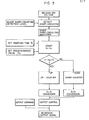
- FIG. 3 A flowchart for explaining the operation performed by the welding machine of the present invention is shown in Fig. 3. The process of the operation will be described hereunder.
- a short-circuiting detection level adjusting circuit inputs a welding arc voltage and cuts off a portion of the welding arc voltage higher than a predetermined level to produce a short-circuiting waveform and then this short-circuiting waveform is shaped to obtain a short-circuiting (detection) pulse.
- the number n of the short-circuiting pulses within the sampling time Ts is counted, and the difference n d between n and a preset number of pulses n is obtained.
- the pulses representing the difference n d are applied to an up-counter, while, if n s - n > 0 holds, the pulses representing the difference n d are applied to a down-counter.
- the digital output of the counters is converted into an analog value through a D/A converter. This analog output is adjusted, and the adjusted analog output is compared with an output command signal for the welding machine to produce a deviation output signal, thereby controlling the output of the welding machine.
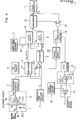
- Fig. 4 shows a block diagram showing an example of the construction of the welding machine of the present invention.
- Reference numeral 1 designates a short-circuiting detector circuit
- numeral 2 a short-circuiting detection level adjusting circuit
- numeral 3 a waveform shaping circuit
- numeral 4 a down-counter
- numeral 5 an up-counter
- numeral 6 a predetermined value n setting circuit
- numeral 7 a sampling time setting circuit
- numeral 8 9 a latch circuit
- numeral 10 a comparator
- numeral 11 a pulse generator
- numeral 12 an up-down counter
- numeral 13 a D/A converter
- numeral 14 a gain control circuit
- numeral 15 a deviation output circuit
- numeral 16 an output command voltage circuit
- numeral 17 a latch circuit control signal generator circuit
- numeral 18, 19 an inverter circuit, respectively, numeral 20, 21 an AND circuit, respectively, and numeral 22 a timing adjusting circuit.
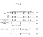
- Fig. 5 shows output voltage waveforms generated in the circuits shown in Fig. 4.
- Fig. 5 designates a welding arc voltage waveform
- (c) short-circuiting (detection) pulses (d) pulses for setting the sampling time Ts
- the short-circuiting detector circuit 1 includes resistors R l , R 2 and a zen er diode ZD 1 .
- the voltage waveform v a shown at (a) in Fig. 5 input to this circuit is cut at a level (A) by the zener diode ZD 1 to produce a waveform shown at (b).
- the signal of the welding arc voltage v a is normally a voltage signal appearing between the welding torch and the welding base metal. In the absence of a welding arc, there appears a no-load voltage whose value is extremely high as compared with the welding arc voltage.
- the zener diode ZD 1 operates to prevent the control circuit of the present invention from being destroyed by this high voltage.
- the short-circuiting detection level adjusting circuit 2 comprises resistors R 3 , R 4 and R 5 , a variable resistor VR 1 , and an operational amplifier IC 1 . It is possible to adjust the short-circuiting detection level by adjusting the variable resistor VR 1 . This operation is represented by the adjustment of the detection level shown by (B) at Fig. 5(b). When the voltage waveform shown below the detection level B in (b) is applied to the waveform shaping circuit 3 in Fig. 4, an output pulse waveform having a constant pulse duration and voltage as shown at Fig. 5(c) is obtained.
- each of the portions of the welding arc voltage v a is indicated by a rectangular pulse waveform.
- This pulse is applied to the down-counter 4.
- the predetermined value n s setting circuit 6 sets a predetermined value n s for the down-counter
- the sampling time setting circuit 7 sets the sampling time Ts for the down-counter 4.
- the pulse duration Ts represents the sampling time.
- the output of the down-counter 4 is counted down from the preset value n s in response to the number of short-circuiting pulses n occuring during the sampling time. If the number of short-circuiting pulses n is smaller than the preset value n s , namely, if the relation n ⁇ n s holds, the output n d of the down counter 4 (which is equal to n minus n) is applied to the latch circuits 8 and 9.
- Numeral 17 designates a latch circuit control signal generator circuit which produces an output waveform shown at Fig. 5(e).
- the latch circuit 8 When the latch signal (e) input to the latch circuit 8 is at a "high” level, the latch circuit 8 inputs a short-circuiting pulse signal from the counter 4, while, when the latch signal (e) is at a "low” level, the latch circuit 8 holds data stored therein.
- the latch signal (e) is applied also the latch circuit 9 through the inverter circuit 18.
- the latch signal (f) thus applied is shown in Fig. 5.
- the latch signals (e) and (f) are in opposite phase to each other.
- the output of the down-counter 4 is applied to both of the latch circuits 8 and 9 as mentioned above, while one of the latch circuits inputs a short-circuiting pulse, the other latch circuit does not input any short-circuiting pulse but it functions to hold the data of the previous cycle (data obtained one sampling time before).
- the terminal A of the AND circuit 20 becomes a "high" level, and therefore the short-circuiting pulse signal is applied through the terminal B of the AND circuit 20 to the up-counter 5.
- the up-counter 5' is also supplied with a signal for determining the sampling time Ts from the sampling time circuit 7.
- This output pulse is applied to the.latch circuits 8 and 9.
- the latch circuits 8 and 9 operate alternately, so that when one of them is supplied with an input signal, the other of them holds the previous data n d applied thereto in a preceding cycle.
- the data thus held is applied to the input terminal A of the comparator 10.
- the input terminal B of the comparator 10 is supplied with a pulse n p from the pulse generator 11.
- the comparator 10 compares the input data applied to its two input terminals A and B.
- the output of the comparator 10 is applied to the input terminal A of the AND circuit 21.
- the output of the comparator 10 remains "high" until the number of pulses n p applied to its input terminal B becomes equal to the number of pulses n d set at its input terminal A.
- the up-down control terminal of the up-down counter 12 is supplied with the carry-out signal of the down-counter 4.
- the carry-out signal of the down-counter 4 is "high” when the relation n s - n > 0 holds, and it is inverted to a "low” level through the inverter circuit 19.
- this "low” signal is applied to the up-down control terminal of the up-down counter 12, then the up-down counter 12 operates as a down-counter.
- the carry-out signal is a "low” level and it is inverted to a "high” level through the inverter circuit 19.
- the counter 12 When this "high" level signal is applied to the up-down control terminal of the up-down counter 12, then the counter 12 operates as an up-counter.
- the carry-out signal passing through the inverter circuit 19 is supplied to the up-down counter 12 through the timing circuit 22. Since the output pulses n d from the up-counter 4 and the down-counter 5 are latched temporarily in the latch circuits 8 and 9, the timing of application of the pulses n d to the up-down counter 12 does not coincide with that of the carry-out signal of the down-counter 4.
- the timing of application of the carry-out signal is adjusted by the timing adjusting circuit 22.
- the output of the up-down counter 12 is applied to the D/A converter 13 so that the digital signal is converted to an analog signal.
- Numeral 14 designates a gain control circuit for controlling the magnitude of the analog output of the D/A converter, and the output of the gain control circuit 14 is connected to the deviation output circuit 15.
- Numeral 16 designates an output command voltage circuit including constituent elements such as a remote controller for adjusting the output of the welding machine.
- the output signal of the output command voltage circuit 16 and the output signal of the gain control circuit 14 are supplied to the deviation output circuit 15 constituted mainly by an operational amplifier IC 2 , the output of which is applied to a control circuit of an output control element (not shown) for the welding machine to control the welding output.
- the output of the deviation output circuit 15 is reduced by the difference pulse number n d to decrease the output voltage of the welding machine, thereby controlling to increase the number of short-circuiting pulses n.
- the output of the deviation output circuit 15 is increased by the difference pulse number n d to increase the output voltage of the welding machine, thereby controlling to reduce the number of short-circuiting pulses n.
- the welding output voltage is immediately increased to prevent the number of short-circuiting times from increasing, while, if the number of short-circuiting times is detected to be smaller than the preset value, the welding output voltage is immediately decreased to maintain an adequate arc length.
- the value of the difference n d can not be greater than the value of n s .
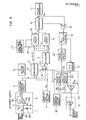
- Figs. 4 and 6 The difference in the construction between Figs. 4 and 6 resides in the gain control circuit.
- the gain control circuit 14 in Fig. 4 is replaced by an up-down gain control circuit 26 in Fig. 6. The operation of this circuit will be explained below.
- the up-down gain control circuit 26 is provided .to control the analog output of the D/A converter 13, and it comprises resistors R 6 , R 7 , R 8 , an operational amplifier IC 3 and analog switches 23 and 24.
- the analog switches 23 and 24 have respective control terminals C 1 and C 2 . upon application of a "high" level input signal to each of the control terminals C 1 and C 2 , the impedance between the input and output of each of the analog switches 23 and 24 becomes low, while, upon application of a "low” level input signal to the control terminals C 1 and C 2 , the impedance between the input and output thereof becomes high.
- the input signal to the timing adjusting circuit 22 becomes "high” when the relation n - n s ⁇ 0 holds, and it becomes “low” when the relation n s - n > 0 holds.
- This input signal is applied to the control terminal C 1 of the analog switch 23 on the one hand, and it is inverted through the inverter 25 and applied to the control terminal C 2 of the analog switch 24 on the other hand.
- the output of the D/A converter 13 passes through the up-down gain control circuit 26 whose gain is determined by the resistor R 7 , since the impedance between the input and output of the analog switch 24 of the up-down gain control circuit 26 becomes low (while, when the impedance between the input and output of the analog switch 23 becomes high).
- the impedance of the resistor R 7 is chosen to be greater than that of the resistor 6.
- the welding arc voltage decrease for a difference n d becomes greater than the welding arc voltage increase for the difference n d of the same magnitude.
- the number of times of short-circuiting occurring between an electrode wire and a base metal during a welding operation is counted by a microcomputer at regular time intervals (at every sampling time Ts), and the difference (n s - n) between the number of times of short-circuiting n thus counted and a short-circuiting constant n s stored beforehand in a storage device such as ROM is calculated.
- n 1 and n 2 are converted into analog values, each of which is used as a feedback signal for controlling a welding output.
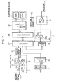
- Fig.'7 is a block diagram showing a construction of the system of the embodiment of the present invention.
- numeral 1 designates a short-circuiting detector circuit
- numeral 2 a short-circuiting detection level adjusting circuit
- numeral 3 a waveform shaping circuit, in .the same manner as Fig. 4.
- Numeral 7 designates a sampling time setting circuit for setting a sampling time Ts, and it is composed of a variable resistor VR2.
- the value of the variable resistor VR2 is applied through a resistor R9 to an A/D converter 30 and is converted into a digital value by the A/D converter 30. Then, this digital value is sent through the interface 27 to the microcomputer 28 to be read thereby.
- Numeral 31 designates a storage device including ROM, RAM, etc. and it is connected to the microcompuer 28 through a buffer and latch circuit 32.
- the microcomputer 28 starts its operation in accordance with a program stored in the storage device 31.
- the microcomputer 28 reads the number of short-circuiting pulses n occurring during the sampling time Ts preset by the sampling time setting circuit 7.
- Numeral 14 designates a gain control circuit for controlling the magnitude of the analog output from the D/A converter 13.
- the output of the gain control circuit 14 is supplied to a deviation output circuit 15 which is constituted mainly by an operational amplifier IC 2 .
- the gain control circuit 14 comprises a resistor Rio, a variable resistor VR 3 and an operational amplifier IC 4 .
- the magnitude of the output signal from the gain control circuit 14 is controlled by the adjustment of the impedance value of the variable resistor VR 3 .
- Numeral 16 designates an output command voltage circuit including a remote controller for adjusting the output of the welding machine.
- the output signal from the output command voltage circuit 16 is applied to a terminal A of the deviation output circuit 15, while, the other terminal B of the deviation output circuit 15 is supplied with an output signal from the gain control circuit 14.
- the output of the deviation output circuit 15 is applied to a control circuit of an output control element (not shown) for the welding machine to control the welding output.
- the microcomputer 28 is programmed so that the welding arc voltage decrease for a difference in the pulse number is greater than the welding arc voltage increase for the difference of the same magnitude, it is possible to improve a response in changing the electrode extension.
- the present invention provides a novel welding machine capable of performing output voltage control for the pulse MIG welding in which a gas containing an inert gas as a main component is used and a consumable electrode wire is fed to a weld part to effect fusion welding by using a pulsating welding current.
- the welding arc voltage is increased to prevent the occurrence of short-circuiting from being increased as soon as short-circuiting occurs at a rate higher than a preset value, while, the welding arc voltage is decreased to provide a proper arc length (which allows the number of short-circuiting times to approach the preset value n s ) as soon as the welding arc voltage increases to reach a state such that short-circuiting occurs less frequently than the preset valde s
- the arc length is always regulated at an adequate value, and therefore the welding arc becomes very stable and it is possible to perform a satisfactory welding operation with only a small amount of spatter. Further, even when the distance between a welding torch and a weld part varies due to an unstable manual operation by the operator, the arc length can be maintained constant. Therefore, the welding operation for setting the welding conditions requiring a considerable degree of skill which has so far been necessary can be eliminated, thereby remarkably improving the welding efficiency and the economy of the welding work.
- the welding machine of the present invention always regulates the arc length to provide an adequate number of short-circuiting times, so that it is possible to effect an efficient welding operation with excellent efficiency.
Landscapes
- Engineering & Computer Science (AREA)
- Physics & Mathematics (AREA)
- Plasma & Fusion (AREA)
- Mechanical Engineering (AREA)
- Arc Welding Control (AREA)
Applications Claiming Priority (6)
| Application Number | Priority Date | Filing Date | Title |
|---|---|---|---|
| JP161317/84 | 1984-07-31 | ||
| JP161315/84 | 1984-07-31 | ||
| JP16131784A JPS6138783A (ja) | 1984-07-31 | 1984-07-31 | 消耗電極式パルスア−ク溶接機 |
| JP16131584A JPS6138781A (ja) | 1984-07-31 | 1984-07-31 | 消耗電極式パルスア−ク溶接機 |
| JP75653/85 | 1985-04-10 | ||
| JP60075653A JPH0632856B2 (ja) | 1985-04-10 | 1985-04-10 | 消耗電極式ア−ク溶接機 |
Publications (2)
| Publication Number | Publication Date |
|---|---|
| EP0170248A2 true EP0170248A2 (fr) | 1986-02-05 |
| EP0170248A3 EP0170248A3 (fr) | 1989-01-18 |
Family
ID=27301902
Family Applications (1)
| Application Number | Title | Priority Date | Filing Date |
|---|---|---|---|
| EP85109525A Withdrawn EP0170248A3 (fr) | 1984-07-31 | 1985-07-29 | Machine de soudage à l'arc par impulsions du type à électrode consommable |
Country Status (3)
| Country | Link |
|---|---|
| US (1) | US4647754A (fr) |
| EP (1) | EP0170248A3 (fr) |
| AU (1) | AU555591B2 (fr) |
Cited By (3)
| Publication number | Priority date | Publication date | Assignee | Title |
|---|---|---|---|---|
| EP0288991A3 (en) * | 1987-04-28 | 1990-05-30 | Matsushita Electric Industrial Co., Ltd. | Consumable electrode arc welding machine |
| EP0520439A3 (en) * | 1991-06-27 | 1994-11-09 | Utp Schweissmaterial | Electronic welding current generator for pulsed-arc welding |
| US6388233B1 (en) | 1997-05-05 | 2002-05-14 | Esab Ab | Method and apparatus for arc welding with melting electrode |
Families Citing this family (14)
| Publication number | Priority date | Publication date | Assignee | Title |
|---|---|---|---|---|
| DE4091340C2 (de) * | 1989-08-02 | 2000-06-21 | Mitsubishi Electric Corp | Impulsschweißvorrichtung |
| JP3206714B2 (ja) * | 1995-11-14 | 2001-09-10 | 日立ビアメカニクス株式会社 | パルスアーク溶接方法および装置 |
| US5756967A (en) * | 1997-04-09 | 1998-05-26 | The United States Of America As Represented By The Secretary Of Commerce | Sensing ARC welding process characteristics for welding process control |
| US6087626A (en) * | 1998-02-17 | 2000-07-11 | Illinois Tool Works Inc. | Method and apparatus for welding |
| JP4036960B2 (ja) * | 1998-03-31 | 2008-01-23 | 株式会社ダイヘン | 消耗電極パルス溶接のアーク長制御方法 |
| US6087627A (en) * | 1998-09-21 | 2000-07-11 | Lincoln Global, Inc. | Method of controlling a welding process and controller therefor |
| US6495798B1 (en) | 2000-09-21 | 2002-12-17 | Lincoln Global, Inc. | Radial tube torch head |
| JP4809014B2 (ja) * | 2005-07-29 | 2011-11-02 | 株式会社ダイヘン | ロボット溶接のアークスタート制御方法 |
| PL1924384T3 (pl) * | 2005-09-12 | 2014-01-31 | Esab Ab | Sposób sterowania spawaniem MIG/MAG i urządzenie spawalnicze stosujące tę metodę |
| US10035209B2 (en) * | 2009-03-18 | 2018-07-31 | Lincoln Global, Inc. | Adaptive GMAW short circuit frequency control |
| JP4807474B2 (ja) | 2009-06-19 | 2011-11-02 | パナソニック株式会社 | 消耗電極式アーク溶接方法および消耗電極式アーク溶接装置 |
| CN111230260A (zh) * | 2018-11-28 | 2020-06-05 | 林肯环球股份有限公司 | 用于控制电弧焊接系统以减少飞溅的方法 |
| US11311958B1 (en) * | 2019-05-13 | 2022-04-26 | Airgas, Inc. | Digital welding and cutting efficiency analysis, process evaluation and response feedback system for process optimization |
| US12673380B2 (en) * | 2020-11-16 | 2026-07-07 | Liburdi Engineering Limited | System and method for preventing stub-outs in GTAW |
Family Cites Families (5)
| Publication number | Priority date | Publication date | Assignee | Title |
|---|---|---|---|---|
| GB1254963A (en) * | 1968-03-01 | 1971-11-24 | Redemat S A | Improvements in the monitoring, and, if desired, controlling metal transfer in welding processes in electric welding |
| DE1806648A1 (de) * | 1968-11-02 | 1970-05-21 | Erdmann Jesnitzer Dr Ing Habil | Vorrichtung und Verfahren zur Kontrolle von Elektroschweissverfahren |
| GB2053762A (en) * | 1979-07-20 | 1981-02-11 | Boc Ltd | Controlling gas-shielded consumable electrode arc welding in dip transfer mode |
| US4320282A (en) * | 1980-02-15 | 1982-03-16 | Rensselaer Polytechnic Institute | Microprocessor based arc-air and welder noise abatement controller |
| GB8306578D0 (en) * | 1983-03-10 | 1983-04-13 | Welding Inst | Short-circuit mig welding |
-
1985
- 1985-07-22 US US06/757,864 patent/US4647754A/en not_active Expired - Lifetime
- 1985-07-23 AU AU45249/85A patent/AU555591B2/en not_active Ceased
- 1985-07-29 EP EP85109525A patent/EP0170248A3/fr not_active Withdrawn
Cited By (3)
| Publication number | Priority date | Publication date | Assignee | Title |
|---|---|---|---|---|
| EP0288991A3 (en) * | 1987-04-28 | 1990-05-30 | Matsushita Electric Industrial Co., Ltd. | Consumable electrode arc welding machine |
| EP0520439A3 (en) * | 1991-06-27 | 1994-11-09 | Utp Schweissmaterial | Electronic welding current generator for pulsed-arc welding |
| US6388233B1 (en) | 1997-05-05 | 2002-05-14 | Esab Ab | Method and apparatus for arc welding with melting electrode |
Also Published As
| Publication number | Publication date |
|---|---|
| AU555591B2 (en) | 1986-10-02 |
| AU4524985A (en) | 1986-02-06 |
| EP0170248A3 (fr) | 1989-01-18 |
| US4647754A (en) | 1987-03-03 |
Similar Documents
| Publication | Publication Date | Title |
|---|---|---|
| US4647754A (en) | Consumable electrode type pulse arc welding machine | |
| US7129443B2 (en) | Method and apparatus for welding with CV control | |
| US4544826A (en) | Method and device for controlling welding power supply to avoid spattering of the weld material | |
| US4300035A (en) | Welding apparatus with time interval control | |
| KR840002190B1 (ko) | 펄스아아크 용접장치 | |
| US5225660A (en) | Consumable-electrode ac gas shield arc welding method and apparatus therefor | |
| US4201906A (en) | Method and apparatus for arc welding | |
| US4300036A (en) | Welding apparatus with arc interval energy control | |
| US4877941A (en) | Power supply system for consumable electrode arc welding and method of controlling the same | |
| EP0241249B1 (fr) | Circuit de régulation pour le sondage à l'arc de composants | |
| EP1036627B1 (fr) | Méthode et appareil pour le soudage électrique à l'arc | |
| JPS6352993B2 (fr) | ||
| US4497997A (en) | Method and apparatus for metal arc welding with constant currents | |
| JP3186539B2 (ja) | アーク溶接の溶滴移行形態設定管理装置 | |
| JP3311403B2 (ja) | アーク溶接自動制御方法及び装置 | |
| JPH0342997B2 (fr) | ||
| JPS61235077A (ja) | 消耗電極式ア−ク溶接機 | |
| JP2587343B2 (ja) | パルスアーク溶接用電源装置 | |
| JPS6138782A (ja) | 消耗電極式パルスア−ク溶接機 | |
| JPS6138781A (ja) | 消耗電極式パルスア−ク溶接機 | |
| JPS6138783A (ja) | 消耗電極式パルスア−ク溶接機 | |
| JPH0331552B2 (fr) | ||
| JPH0321269B2 (fr) | ||
| JPH0230377A (ja) | パルス放電装置 | |
| JPS6188972A (ja) | パルスアーク溶接機 |
Legal Events
| Date | Code | Title | Description |
|---|---|---|---|
| PUAI | Public reference made under article 153(3) epc to a published international application that has entered the european phase |
Free format text: ORIGINAL CODE: 0009012 |
|
| AK | Designated contracting states |
Designated state(s): DE GB |
|
| PUAL | Search report despatched |
Free format text: ORIGINAL CODE: 0009013 |
|
| AK | Designated contracting states |
Kind code of ref document: A3 Designated state(s): DE GB |
|
| 17P | Request for examination filed |
Effective date: 19890313 |
|
| 17Q | First examination report despatched |
Effective date: 19901218 |
|
| STAA | Information on the status of an ep patent application or granted ep patent |
Free format text: STATUS: THE APPLICATION IS DEEMED TO BE WITHDRAWN |
|
| 18D | Application deemed to be withdrawn |
Effective date: 19910430 |
|
| RIN1 | Information on inventor provided before grant (corrected) |
Inventor name: HIRASAWA, KAZUSHIGE |