EP0170331B1 - Couple de roues dentées - Google Patents
Couple de roues dentées Download PDFInfo
- Publication number
- EP0170331B1 EP0170331B1 EP85201215A EP85201215A EP0170331B1 EP 0170331 B1 EP0170331 B1 EP 0170331B1 EP 85201215 A EP85201215 A EP 85201215A EP 85201215 A EP85201215 A EP 85201215A EP 0170331 B1 EP0170331 B1 EP 0170331B1
- Authority
- EP
- European Patent Office
- Prior art keywords
- gear
- stop
- gear member
- drivable
- driving
- Prior art date
- Legal status (The legal status is an assumption and is not a legal conclusion. Google has not performed a legal analysis and makes no representation as to the accuracy of the status listed.)
- Expired
Links
- 230000002441 reversible effect Effects 0.000 claims description 14
- 230000033001 locomotion Effects 0.000 claims description 11
- 230000007246 mechanism Effects 0.000 claims description 6
- 230000002035 prolonged effect Effects 0.000 claims 1
- 230000005540 biological transmission Effects 0.000 description 79
- 230000015572 biosynthetic process Effects 0.000 description 2
- 238000004519 manufacturing process Methods 0.000 description 2
- 238000000034 method Methods 0.000 description 2
- 230000004048 modification Effects 0.000 description 2
- 238000012986 modification Methods 0.000 description 2
- 230000008569 process Effects 0.000 description 2
- 230000008859 change Effects 0.000 description 1
- 238000006073 displacement reaction Methods 0.000 description 1
- 230000003993 interaction Effects 0.000 description 1
- 230000000737 periodic effect Effects 0.000 description 1
- 238000005096 rolling process Methods 0.000 description 1
- 230000001960 triggered effect Effects 0.000 description 1
Images


Classifications
-
- F—MECHANICAL ENGINEERING; LIGHTING; HEATING; WEAPONS; BLASTING
- F16—ENGINEERING ELEMENTS AND UNITS; GENERAL MEASURES FOR PRODUCING AND MAINTAINING EFFECTIVE FUNCTIONING OF MACHINES OR INSTALLATIONS; THERMAL INSULATION IN GENERAL
- F16H—GEARING
- F16H27/00—Step-by-step mechanisms without freewheel members, e.g. Geneva drives
- F16H27/04—Step-by-step mechanisms without freewheel members, e.g. Geneva drives for converting continuous rotation into a step-by-step rotary movement
- F16H27/08—Step-by-step mechanisms without freewheel members, e.g. Geneva drives for converting continuous rotation into a step-by-step rotary movement with driving toothed gears with interrupted toothing
-
- Y—GENERAL TAGGING OF NEW TECHNOLOGICAL DEVELOPMENTS; GENERAL TAGGING OF CROSS-SECTIONAL TECHNOLOGIES SPANNING OVER SEVERAL SECTIONS OF THE IPC; TECHNICAL SUBJECTS COVERED BY FORMER USPC CROSS-REFERENCE ART COLLECTIONS [XRACs] AND DIGESTS
- Y10—TECHNICAL SUBJECTS COVERED BY FORMER USPC
- Y10T—TECHNICAL SUBJECTS COVERED BY FORMER US CLASSIFICATION
- Y10T74/00—Machine element or mechanism
- Y10T74/19—Gearing
- Y10T74/1987—Rotary bodies
- Y10T74/19874—Mutilated
Definitions
- the invention relates to a gear transmission with a driving gear part that can be driven in at least one drive direction and a gear part that can be driven by this, one of which has a toothing delimited by two ends, which for engaging and disengaging the two gear parts when driving the driving gear part via at least one The end of the same can be brought into and out of engagement with the toothing on the other gear part, wherein, when the gear parts are disengaged, one of them projects with its toothing into the adjustment path of the toothing of the other gear part and, in the case of engaged gear parts, at least n of the gear part having the limited toothing Teeth are in engagement with the toothing on the other gear part, where n is an integer greater than zero, and which is one of them for engaging the same in at least one drive direction of the driving gear part Bear the associated drive direction associated pair of control stops arranged offset in the direction of the tooth width with respect to the toothing, which come into active connection in pairs when the two gear parts engage by means of stop surfaces provided on them, each stop surface of a control stop
- Such a transmission is known for example from DE-PS-143 943.
- This known transmission is a non-reversible transmission, the two transmission parts of which are designed as gearwheels and in which both the driving and the driven gearwheel always rotate in the same direction of rotation, the driving gearwheel having a closed toothing one continuous rotary motion and the drivable gear having a limited toothing performs a periodic rotary motion.
- the drivable gearwheel in order to engage the two gearwheels when driving the driving gearwheel, the drivable gearwheel must additionally be triggered with a separate device, after which only the control stops come into active connection with their stop faces and ensure that the two gearwheels engage properly.
- a separate device complicates the transmission and represents an additional outlay.
- the invention has set itself the task of designing a gear transmission of the type mentioned in such a way that it is easily reversible, that the engagement of the two transmission parts when driving the driving transmission part takes place without additional impingement of the drivable transmission part, and that the operating position is assumed precisely and reproducibly can.
- the invention is characterized in that, in order to form a gear transmission which is optionally reversible between two end positions, the driving gear part can be driven alternately in two mutually opposite drive directions, that the stop face of the control stop carried by the driving gear part has the same geometric shape as that when the gear parts are brought into engagement in the drive direction of the driving gear part front tooth flank surface of the first meshing tooth of this gear part and the stop surface of the control stop carried by the drivable gear part have the same geometric shape as when engaging the gear parts in the drive direction of the drivable gear part back tooth flank surface of the first meshing tooth Gear part and that at least one of the two pairs of interacting control stops over the tip circle the toothing of the transmission part carrying this control stop is extended and its stop surface is continued according to the tooth flank geometry, whereby when the transmission parts are disengaged, the control stop carried by the drivable transmission part lies with its stop surface in the adjustment path of the stop surface of the control stop carried by the driving transmission part and for engaging the two Gear parts of the driving gear
- an optionally reversible gear transmission is created in a simple manner, in which it is additionally achieved that when the driving transmission part is driven, the part carried by it Control stop with its abutment surface abuts against the abutment surface of the control stop carried by the drivable transmission part and thereby takes it with it, so that the two transmission parts engage their teeth in a particularly simple manner, and that the operating position is precisely and reproducibly assumed by the limit stop.
- both gear parts can be designed as a gear wheel or one can also be designed as a toothed rack, which is known to be considered in toothed wheel gear technology as a gear wheel with an infinitely large diameter.
- the control stop carried by the drivable transmission part with its stop surface lies in the adjustment path of the stop surface of the control stop carried by the driving transmission part when the transmission parts are disengaged.
- a reversible gear transmission consisting of five gears is known per se from DE-PS-348 517, but in which the reversing process takes place with a periodicity defined by the structure of the transmission, so that the reversing process cannot be freely selected , as is the case with the transmission according to the invention.
- a gearwheel is provided with a tooth-like projection protruding beyond the tip circle of its toothing, which for engaging this gearwheel enters with another gearwheel into a tooth-gap-like depression extending under the root circle of the further gearwheel.
- the projection has a completely different shape than the teeth of this gear and therefore the recess of the further gear has a completely different shape than the tooth gaps of this additional gear, so that the engagement surfaces on the projection and in when the two gears mesh with one another Recess are not conform to the tooth flank surfaces of the gears, which is why this known gear only ensures that both gears engage with each other without hindrance if the formation of the projection and the recess interacting therewith are very precise to the position and shape of the Gear teeth are adapted, but this requires high precision in the manufacture of the gear parts and thus brings with it a considerable increase in price.
- a gear transmission is known from FR-A-790 174, the driving gear A also having areas during which rotational speed is transmitted to a driven wheel D (toothing area B) and areas which continue to rotate when the driving wheel A bring the driven wheel D to a standstill (area C).
- Both gears A and D also have control stops (at 2 and 1, 6, respectively), the tooth flanks of which have the same geometrical shape as the tooth flank surfaces of the intermeshing tooth which are in front when the wheels are brought into engagement.
- one of the Control stops beyond the tip circle of the toothing in the radial direction.
- the tax stops are 2; 1. 6 also attached axially next to the main toothing.
- a fixed limit stop and a counter stop provided on the drivable gear part are not known from FR-A-790 174.
- the driving gear part has a further limit stop which, when the gear parts are disengaged, is opposite a further counterstop provided on the driving gear part and blocks an adjustment of the drivable gear part in the drive direction as when the gear parts are engaged.
- the drivable gear part with its counter-stop and the further counter-stop is positively fixed between the fixed and the driving gear part provided limit stop when the gear parts are disengaged, no external forces acting on them, which is advantageous with regard to an uninfluenced and smooth movement sequence in the transmission .
- the interaction of the further counter-stop on the drivable gear part with the further limit stop on the driving gear part additionally ensures that the gear teeth of the gear parts remain disengaged when they are disengaged.
- the further limit stop on the driving gear part can be formed, for example, by an extension projecting from a tooth-free section of the driving gear part, which cooperates with a tooth provided as a further counterstop on the drivable gear part of the toothing of the drivable gear part and is opposite this when the gear parts are disengaged. It has proven to be particularly advantageous if the further counter-stop is formed by an extended control stop provided on the drivable transmission part. In this way, the control stop on the drivable transmission part is used not only for engaging the transmission parts, but also for determining the position of the drivable transmission part when the transmission parts are disengaged, the stops used for this determination having no restrictive influence on the formation of the toothings.
- Fig. 1 shows schematically in plan view an optionally reversible between two end positions gear transmission according to a first embodiment, the two gears for engaging them in a drive direction of the driving gear have a pair of control stops, the two gears occupy one of their end positions and with their teeth disengaged.
- Fig. 2 shows in a section along the circular arc-shaped line 11-11 in Fig. 1, which corresponds to a partial arc of the driving gear, a detail with the control stop on the driving gear.
- Fig. 3 shows in a section along the circular arc-shaped line 111-111 in Fig. 1, which corresponds to a partial arc of the drivable gear, a detail with the control stop on the drivable gear.
- FIG. 4 shows, analogously to FIG. 1, the gear transmission according to FIG. 1, the two gear wheels taking up the other of their two end positions and being in engagement with their toothings.
- FIG. 5 shows, analogously to FIG. 1, an optionally reversible gear transmission according to a second exemplary embodiment, the two gear wheels of which have two pairs of control stops for engaging the same in both drive directions of the driving gear wheel, the two gear wheels occupying one of their two end positions and with their Gears are disengaged.
- FIG. 6 shows the gear transmission according to FIG. 5, the two gear wheels taking up their other end position from their one end position after their adjustment and again being out of engagement with their toothings after they have been engaged when adjusting the gear wheels.
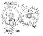
- Fig. 7 shows an optionally reversible gear transmission according to a third embodiment, the two gears for engaging them in a drive direction of the driving gear have a pair of control stops, the control stop on the driving gear, which has a limited toothing, in the drive direction of the same for engagement of the two gears is arranged in front of the limited toothing of the driving gear.
- FIG. 8 shows, in an analog section like FIG. 2, a detail with the control stop on the driving gear of the gear transmission according to FIG. 7.
- the gear transmission 1 has a gear 3 rotatably mounted about a shaft 2 as the driving gear part and a gear 5 rotatably mounted about a shaft 4 as the drivable transmission part.
- the driving gear 3 necessarily has a toothing 8 delimited by two ends 6 and 7.
- the drivable gear 5 has a toothing 9, which is closed and only partially shown, covering the entire circumference of the gear 5, but only a part of which is brought into engagement with the limited toothing 8 on the driving gear 3.
- the gear wheel 5 could, for example, also have a tooth-free section in the toothing region indicated by dash-dotted lines, so that the drivable gear wheel would then have a toothing delimited by two ends.
- the fact that one of the two gear wheels necessarily has limited toothing forms the prerequisite for the two gear wheels with their toothings to be able to be brought into and out of engagement.
- the limited toothing 8 for engaging and disengaging the two gearwheels 3 and 5 when driving the driving gearwheel 3 can be brought into and out of engagement with the toothing 9 on the driven gearwheel 5 via the end 6 thereof.
- the toothed wheel 5 projects with its toothing 9 into the adjustment path of the limited toothing 8 on the toothed wheel 3, as shown in FIG. 1.
- the tooth of the gear 3 designated by the reference numeral 14 is no longer in engagement with the toothing 9 of the gear 5 in the situation shown in FIG. 4.
- the representation of the toothings 8 and 9 is schematic for the sake of simplicity and that the present toothings are involute toothings, that is to say the geometrical course of the tooth flank surfaces corresponds to involutes.
- the driving gear 3 can be driven by a motor 15 via a drive connection 16, shown schematically with a dash-dotted line, between its two end positions alternately in two mutually opposite drive directions, in which drive connection an overload clutch on the motor side, which is effective in two opposite directions of rotation and acts, for example, as a wrap spring clutch is formed, and a gear-side self-locking gear, such as a worm gear, is included.
- the motor 15 can be connected to a supply voltage V1 via a first switch 17 and to a supply voltage V2 via a second switch 18.
- the motor 15 runs in such a direction of rotation that it drives the driving gear 3 via the drive connection 16 in the drive direction indicated by the arrow 19, in which the two gears 3 and 5 with their toothings 8 and 9 in Intervention can be brought.
- the motor 15 runs in the opposite direction of rotation, so that it then drives the driving gear 3 via the drive connection 16 in the opposite drive direction indicated by the arrow 20, in which the two gears 3 and 5 with their toothings except Intervention can be brought.
- the driving gear 3 can, as mentioned, be rotated between two end positions, namely a rest position shown in FIG. 1 and an operating position shown in FIG. 4, in which the gear 3 in each case also by the self-locking gear after the motor 15 has been stopped by opening the switches 17 or 18 is held.
- the rest position of the driving gear 3 is determined by a first fixed limit stop 21, against which a counter stop 22 provided on the driving gear 3 and projecting in the axial direction is supported when the gear 3 is in its rest position, as shown in FIG. 1 .
- the operating position of the gear wheel 3 is determined by a second fixed limit stop 23, against which the counter stop 22 is supported when the gear wheel 3 is in its operating position, as shown in FIG. 4.
- the drivable gear wheel 5 can also be rotated between two end positions, namely a rest position shown in FIG. 1 and an operating position shown in FIG. 4.
- the two gears are brought into engagement, as described in detail below, and the drivable gear 5 is rotated from its rest position into its operating position in the drive direction indicated by the arrow 24.
- the driving gear 3 in the opposite drive direction 20 that drivable gear driven in the opposite direction in the direction of arrow 25 the drivable gear 5 is rotated from its operating position to its rest position and the two gears are disengaged again.
- an arm 26 is connected, which can be articulated, for example, with an intermediate lever for transmission of adjustment movement to other parts.
- the rest position of the drivable gear 5 is defined by a further fixed limit stop 27 which, when the gears 3 and 5 are disengaged, is opposite a counter stop 28 provided on the drivable gear 5 and projecting therefrom in the axial direction and thereby an adjustment of the drivable gear 5 in the Drive direction 25 as blocked when disengaging the gears.
- the counter-stop 28 on the drivable gear 5 is held against the fixed limit stop 27 by the force of a spring 29.
- the spring 29 is formed by a leg spring having a plurality of turns and placed on the shaft 4, the leg 30 of which lies closer to the drivable gear 5 in the axial direction and is attached to an extension 31 provided on the drivable gear 5 and another which is further away from the drivable gear Leg 32 is supported on a further fixed stop 33.
- the operating position of the drivable gear 5 is determined by the engaged teeth 10, 11 and 12, 13 of the two toothings 8 and 9 by the driving gear 3 held in its operating position.
- the two gears 3 and 5 carry a pair of control stops 34 and 35 which are arranged offset in the direction of the tooth width, that is to say in the axial direction of the gears, in the drive direction 19 of the driving gear 3.
- the control stops 34 and 35 come into positive engagement when the two gear wheels 3 and 5 are engaged in pairs via stop surfaces 36 and 37 provided on them.
- Each stop surface 36 or 37 of a control stop 34 or 35 has the same geometrical, ie involute, shape as that when the gears 3 and 5 are brought into engagement as the first tooth flank surface 38 or 39 of the tooth 40 or 39 which is the first to come into engagement.
- each stop surface 36 or 37 is aligned in the direction of the tooth width with the tooth flank surface 38 or 39 which first comes into drive connection.
- the stop surface 36 of the control stop 34 carried by the driving gearwheel 3 has the same geometric shape
- the stop surface 37 of the control stop 35 carried by the drivable gear wheel 5 has the same geometric shape as the tooth flank surface 39 of the tooth 41 of this gear wheel 5 which is the first to engage when it engages in the drive direction 24 of the drivable gear wheel 5.
- control stop 35 on the gear wheel 5 is extended beyond the tip circle of the toothing 9 of the gear wheel 5 carrying the control stop 35 and its stop surface 37 continues according to the tooth flank geometry, that is to say in accordance with the involute shape of the tooth flank surface 39 .
- the control stop 34 is formed by an extension of the toothed wheel 3 that overlaps with the tooth 40 in the direction of the tooth width and is connected to it in one piece.
- the control stop 35 is formed by an extension of the gear wheel 5, which overlaps the tooth gap between the tooth 41 and the tooth 42 lying in the direction of the arrow 24 next to the tooth 41 in the direction of the tooth width, and is integrally connected to the two teeth 41 and 42.
- the control stop 34 comes into a position shown in dotted lines in FIG. 1, in which the stop surface 36 of the control stop 34 comes into contact with the stop surface 37 of the control stop 35.
- the control stop 34 takes the control stop 35 in a form-fitting manner, whereby the drivable gear 5 is rotated along with the two involute-running stop surfaces 36 and 37, respectively, with the tooth flank surfaces 38 and 39, which are the first to be in drive connection as the first teeth 40 and 41, which are in engagement, are aligned, cooperate in a form-fitting manner and essentially roll away from one another.
- the abutment surfaces 36 and 37 ensure a constant translation during rolling and that the two toothings 8 and 9 come into contact with one another even before the teeth 40 and 41, which come into engagement first Relative position to each other are aligned so that the tooth flank surfaces 38 and 39 aligned with the stop surfaces 36 and 37 come into contact with one another with certainty without any hindrances, so that an undisturbed, continuously running, perfect engagement of the two toothings 8 and 9 is ensured. This engagement takes place completely automatically when the driving gear 3 is driven by the interacting control stops 34 and 35.
- the drivable gear 5 is driven by the driving gear 3 via the Gearings 8 and 9 driven, which takes place against the force of the spring 29.
- the driving gear 3 has reached its operating position in which the counter-stop 22 of the gear 3 abuts against the fixed limit stop 23
- the power transmission from the motor 15 to the driving gear 3 is interrupted by the overload clutch contained in the drive connection 16 and the driving gear 3 held by the self-locking gear in its operating position, as a result of which the drivable gear wheel 5 is then held in its operating position via the toothings 8 and 9 which are in engagement with one another.
- the gear transmission 1 is thus in its second end position and the switch 17 can be opened again.
- the switch 18 In order to bring the gear transmission 1 back into its first end position from the second end position shown in FIG. 4, the switch 18 must be closed. An erroneous closing of the switch 17 in this situation remains ineffective because the counter stop 22 of the gear 3, which is supported on the limit stop 23, prevents this gear 3 from rotating against the drive direction 20 and the overload clutch in the drive connection 16 interrupts the transmission of power to the driving gear 3.
- the motor 15 drives the driving gear 3 in the drive direction 20 via the drive connection 16, so that the gear 3 leaves its operating position shown in FIG. 4.
- the drivable gear 5 is carried along via the meshing gears 8 and 9, the spring 29 supporting the rotation of the gear 5.
- the spring 29 ensures that the gear 5 is returned to its rest position, in which the counter-stop 28 of the gear 5 is supported on the fixed limit stop 27 and in which the control stop 35 on the driven gear 5 with its stop surface 37 is in the adjustment path of the stop surface 36 of the control stop 34 on the driving gear 3.
- the overload clutch in the drive connection 16 interrupts the power transmission from the motor 15 to the gear 3 and the self-locking gear keeps the gear 3 in its rest position.
- the gear transmission 1 is thus again in its first end position and the switch 18 can be opened again.
- the measures according to the invention provide, in a particularly simple manner, an optionally reversible gear transmission between two end positions, the two gears of which can be automatically brought into engagement with one another by the provision of the two control stops, whereby due to the involute course of the stop surfaces of the control stops it is certain that the gears are engaged evenly, undisturbed and precisely.
- the gearwheels are disengaged, the position of the drivable gearwheel is very simply determined by a fixed stop, against which this gearwheel is held by spring force.
- Such a gear mechanism which can optionally be reversed between two end positions, can be used very advantageously, for example, in a video magnetic tape device for a magnetic tape accommodated in a cassette, which can be guided out of the cassette with at least one tape guide adjustable between two positions and looped around a tape guide drum, in which case that Drivable gear of the gear transmission via a lever gear ensures a uniform adjustment of the tape guide between its two positions, which is important in order to protect the magnetic tape as optimally as possible.
- this is only one example of an application of such a gear transmission, to which it is not limited.
- control stops can be interchanged, that is, the extended control stop can be provided on the driving gear and the other control stop on the drivable gear.
- both gears can also have a control stop extended beyond the tip circle of the gear in question.
- a toothed rack can also be provided as the drivable gear part, which is then driven back and forth by the driving gear.
- the driving gear part can also be designed as a toothed rack, which can then be driven back and forth and drives the driven gear.
- the driving gear wheel can be provided with a self-contained toothing, in which case the drivable gear wheel must necessarily have a toothing delimited by two ends, one end of which is then determined by the tooth whose tooth flank is flush with the stop face of the control stop, whereby the tooth-free portion of this tooth extends in the drive direction of the drivable gear as when the gears are engaged.
- toothing with a different tooth flank geometry can also be provided, for example cycloid toothing, in which case the stop face of an extended control stop has a course that continues according to the cycloid-shaped course of the tooth flank surfaces.
- the drive connection between the motor and the driving gearwheel can also have a different structure and be constructed, for example, without an overload clutch, in which case the driving gearwheel can actuate a switch each time one of its two end positions is reached, which switches the motor off from the supply voltage in question.
- the driven gear can also be driven differently than via the arm attached to the gear, for example via a further gear that engages with the driven gear.
- the spring that holds the drivable gear in its rest position does not, of course, have to act directly on this gear, but can also act on the arm protruding from the gear or on another part that can be driven by the arm.
- a separate controllable holding device could also be provided, which adjusts the drivable gearwheel against a fixed limit stop after the disengagement of the gearwheels and holds it against it.
- gear transmission 1 differs from the gear transmission described above with reference to FIGS. 1 to 4 inter alia in that the two gears 3 and 5 are disengaged in both end positions of the gear transmission and starting from the respective end position in both drive directions 19 and 20 of the driving gear 3 can be brought into engagement.
- the two gears 3 and 5 have two pairs of control stops 34, 35 and 43, 44 arranged offset in the direction of the tooth width in relation to the toothings 8 and 9, the pair of drive direction 19 formed by the control stops 34 and 35 and that by the Control stops 43 and 44 formed pair of the drive direction 20 of the driving gear 3 is assigned.
- each stop surface 45 or 46 of a control stop 43 or 44 has the same geometrical, ie involute, shape as that when the gears 3 and 5 are brought into engagement as the first tooth flank surface 47 or 48 of the tooth 49 or 48 50 of the gear 3 or 5 carrying it.
- Each stop surface 45 or 46 is aligned in the direction of the tooth width with the tooth flank surface 47 or 48 which is the first to come into drive connection.
- the stop surface 45 of the one carried by the driving gear 3 Control stop 43 has the same geometric profile as the tooth flank surface 47 of the tooth 49 of this tooth wheel 3 which comes into engagement first as it engages in the drive direction 20 of the driving gear wheel 3.
- the abutment surface 46 of the control stop 44 carried by the drivable gear 5 has the same geometrical shape as the tooth flank surface 48 of the tooth 50 of the gear 5 which is the first to engage when it engages in the drive direction 25 of the drivable gear 5.
- control stop 44 provided on the drivable gear wheel 5 is in turn extended beyond the tip circle of the toothing 9 of this gear wheel 5 and its stop surface 46 continues according to the tooth flank geometry, that is to say in accordance with the involute shape of the tooth flank surface 48.
- the control stop 43 is formed by an extension of the toothed wheel 3 that overlaps with the tooth 49 in the direction of the tooth width and is connected to the tooth 3 in one piece.
- the control stop 44 is by an overlap of the tooth gap between the tooth 50 and the tooth 51 lying in the direction of arrow 25 next to the tooth 50 in the direction of the tooth width, with the two teeth 50 and 51 and also integrally connected to the base body of the gear 5 of the gear 5 formed.
- the control stop 35 has the same design as the control stop 44, with a high degree of stability being achieved for the two control stops 35 and 44 by the one-piece connection to the base body of the gear wheel 5.
- the drivable gear 5 is also fixed in a different manner in its two end positions.
- the counter-stop 28 interacts on the one hand with the fixed limit stop 27 and on the other hand with a further fixed limit stop 52.
- the provision of these fixed limit stops 27 and 52 always ensures that each control stop 35 or 44 on the driven gear 5 with its stop surface 37 or 46 in the displacement of the stop surface 36 or 45 of the control stop 34 or 43 interacting with it in pairs on the driving Gear 3 remains.
- the driving gear 3 has two further limit stops 53 and 54 which protrude from the driving gear 3 in the axial direction.
- a further limit stop 53 or 54 provided on the driving gearwheel 3 is opposite a further counter-stop on the driven gearwheel 5.
- Each further counterstop is in this case formed in a simple manner by an extended control stop 35 or 44, the shape of the further limit stop 53 or 54 being adapted to the free end of the extended control stop 35 or 44 cooperating with it.
- the further limit stop 53 or 54 blocks an adjustment of the drivable gear 5 in the drive direction 24 or 25 as when the gears are brought into engagement.
- the drivable gear 5 with its counter stop 28 and one of its two control stops 35 and 44 between a fixed limit stop 27 and 52 and one provided on the driving gear 3, with this adjustable further limit stop 53 and 54 in a form-fitting manner in its Determined respective end position, so that no external forces, such as are exerted by a spring, act on the drivable gear, which is advantageous with regard to an uninfluenced and smooth movement sequence in the transmission. Since the drivable gear 5 is disengaged from the driving gear in its two end positions, the respective position of the drivable gear in its end positions can advantageously be selected in a relatively wide range independently of the two end positions of the driving gear.
- the further limit stops 53, 54 provided on the same are also adjusted so that they are moved away from the extended control stops 35, 44 and are therefore released.
- the lengthened control stop in question can also be adjusted analogously to the embodiment described above according to FIGS. 1 to 4, the teeth 8 and 9 of the two gears 3 and 5 are automatically engaged. This engagement takes place due to the design and arrangement of the stop surfaces of the control stops as well as in the previously described embodiment in a particularly safe, trouble-free and uniform manner.
- Such a gear transmission can, for example, advantageously be used in a video magnetic tape device for a magnetic tape accommodated in a cassette, which can be guided out of the cassette with a threading device that can be adjusted between a threading position and a threading position and can be looped around a tape guide drum and that with a course of one wound around the tape guide drum inactive position in an active position adjusted belt tension sensor cooperates, are used to adjust the belt tension sensor, the driving gear then being designed as a toothed threading ring and being part of the threading device and the gear which can be driven with limited toothing adjusts the belt tension sensor.
- Each stop surface 36 or 37 has one along the respective pitch circle Distance from this tooth flank surface 38 or 39, which corresponds to k times the pitch division t o , where k is an integer between zero and n-1.
- k 1 is selected, which means that each stop surface 36 or 37 is opposite the tooth flank surface 38 or 39, which is the first to be connected to the drive, by the distance of the pitch division t o in the drive direction 19 or 24 of the gear 3 or 5 is arranged in front as when engaging the same.
- the control stops 34 and 35 align the toothings 8 and 9 earlier in their relative position to one another via their form-fittingly interacting stop surfaces 36 and 37 than is the case with the gear transmission according to FIGS. 1 to 4 the case is, again with certainty to ensure a uniform and perfect engagement of the toothings, the tooth flank surfaces 38 and 39 being the first to be moved towards one another and coming into drive connection.
- the above-mentioned distance between each stop surface 36 or 37 and the tooth flank surface 38 or 39 which is the first to come into drive connection may be at most (n-1) times the pitch division t o .
Landscapes
- Engineering & Computer Science (AREA)
- General Engineering & Computer Science (AREA)
- Mechanical Engineering (AREA)
- Transmission Devices (AREA)
- Structure Of Transmissions (AREA)
Claims (4)
Applications Claiming Priority (2)
| Application Number | Priority Date | Filing Date | Title |
|---|---|---|---|
| AT2482/84A AT393549B (de) | 1984-08-01 | 1984-08-01 | Zahnradgetriebe |
| AT2482/84 | 1984-08-01 |
Publications (2)
| Publication Number | Publication Date |
|---|---|
| EP0170331A1 EP0170331A1 (fr) | 1986-02-05 |
| EP0170331B1 true EP0170331B1 (fr) | 1988-12-14 |
Family
ID=3535103
Family Applications (1)
| Application Number | Title | Priority Date | Filing Date |
|---|---|---|---|
| EP85201215A Expired EP0170331B1 (fr) | 1984-08-01 | 1985-07-19 | Couple de roues dentées |
Country Status (5)
| Country | Link |
|---|---|
| US (1) | US4722239A (fr) |
| EP (1) | EP0170331B1 (fr) |
| JP (1) | JPS6182049A (fr) |
| AT (1) | AT393549B (fr) |
| DE (1) | DE3566824D1 (fr) |
Families Citing this family (14)
| Publication number | Priority date | Publication date | Assignee | Title |
|---|---|---|---|---|
| US5546821A (en) * | 1993-11-08 | 1996-08-20 | Brackett; Douglas C. | Motion arrester for a conjugate drive mechanism |
| US5351567A (en) * | 1993-11-08 | 1994-10-04 | Brackett Douglas C | Motion arrester for a conjugate drive mechanism |
| US5513541A (en) * | 1994-03-18 | 1996-05-07 | Brackett; Douglas C. | Conjugate drive mechanism |
| US5445039A (en) * | 1994-03-18 | 1995-08-29 | Brackett; Douglas C. | Conjugate drive mechanism |
| US20020187031A1 (en) * | 2001-06-08 | 2002-12-12 | Boyanich Joseph E. | Electrically actuated push plate assembly |
| EP1267371A1 (fr) * | 2001-06-15 | 2002-12-18 | ABB PATENT GmbH | Dispositif de transmission à mouvement de rotation intermittant pour un commutateur |
| JP5290318B2 (ja) | 2007-11-29 | 2013-09-18 | ダウ グローバル テクノロジーズ エルエルシー | トナーとして有用なコンパウンドおよびその形成方法 |
| DE102009007900A1 (de) * | 2009-02-06 | 2010-08-12 | Huf Hülsbeck & Fürst Gmbh & Co. Kg | Getriebeeinheit mit einer Nachlauffunktion |
| JP5614963B2 (ja) * | 2009-09-25 | 2014-10-29 | 株式会社ケーヒン | 駆動力伝達機構 |
| EP2689164B1 (fr) * | 2011-03-22 | 2015-01-07 | Aktiebolaget SKF | Élément denté à capteur de vibrations |
| US10426637B2 (en) | 2015-05-11 | 2019-10-01 | The Hong Kong Polytechnic University | Exoskeleton ankle robot |
| FR3046260B1 (fr) * | 2015-12-29 | 2018-07-27 | Systemes Moteurs | Dispositif de transmission de mouvement par engrenage et systeme d'actionnement le comprenant |
| JP6218196B2 (ja) * | 2016-03-23 | 2017-10-25 | 株式会社東海理化電機製作所 | 歯車駆動装置 |
| CN111765225B (zh) * | 2020-05-21 | 2022-07-08 | 西安理工大学 | 一种带位置调整的不完全齿轮自动啮合装置 |
Family Cites Families (16)
| Publication number | Priority date | Publication date | Assignee | Title |
|---|---|---|---|---|
| DE143943C (fr) * | ||||
| US1142051A (en) * | 1910-06-20 | 1915-06-08 | Providence Blower Company | Variable-speed gear. |
| DE348517C (de) * | 1920-01-27 | 1922-02-10 | Carl Bach | Umkehrgetriebe |
| US1758206A (en) * | 1927-10-27 | 1930-05-13 | Delta Star Electric Co | Rotary switch |
| FR790174A (fr) * | 1935-05-17 | 1935-11-15 | Engrenage progressif | |
| DE767268C (de) * | 1936-10-27 | 1952-03-31 | Demag Ag | Endschalterantrieb |
| DE707242C (de) * | 1938-08-09 | 1941-06-17 | Carl Schenck Maschinenfabrik D | Getriebe zur abwechselnden Bewegung und Sperrung einer getriebenen Welle mit teilverzahntem treibendem Rad |
| BE516059A (fr) * | 1951-12-11 | |||
| US2881630A (en) * | 1956-10-09 | 1959-04-14 | Librascope Inc | Transfer mechanism |
| DE2210701A1 (de) * | 1972-03-06 | 1973-09-13 | Kieninger & Obergfell | Zahnschaltwerk mit zylinderverriegelung |
| US3768325A (en) * | 1972-09-15 | 1973-10-30 | Bourns Inc | Multiturn adjustment potentiometer ratcheting mechanism |
| JPS5228947B2 (fr) * | 1972-11-20 | 1977-07-29 | ||
| FR2268967A1 (en) * | 1974-04-29 | 1975-11-21 | Sigma Hydraulique | Linear to rotary movement converter - uses inclined tooth crown on rod to increase torque with gear wheel |
| US4023813A (en) * | 1976-01-12 | 1977-05-17 | James T. Dennis | Automatic record changer with cycle delay to facilitate changing of thin, lightweight records |
| US4059024A (en) * | 1976-11-12 | 1977-11-22 | North American Philips Corporation | Gear train with integral stop |
| DE2936004A1 (de) * | 1979-09-06 | 1981-04-16 | Klöckner-Humboldt-Deutz AG, 5000 Köln | Zahntriebschaltwerk mit zylinderverriegelung |
-
1984
- 1984-08-01 AT AT2482/84A patent/AT393549B/de not_active IP Right Cessation
-
1985
- 1985-07-19 EP EP85201215A patent/EP0170331B1/fr not_active Expired
- 1985-07-19 DE DE8585201215T patent/DE3566824D1/de not_active Expired
- 1985-08-01 JP JP60168648A patent/JPS6182049A/ja active Pending
-
1987
- 1987-06-03 US US07/058,641 patent/US4722239A/en not_active Expired - Fee Related
Also Published As
| Publication number | Publication date |
|---|---|
| ATA248284A (de) | 1991-04-15 |
| AT393549B (de) | 1991-11-11 |
| EP0170331A1 (fr) | 1986-02-05 |
| US4722239A (en) | 1988-02-02 |
| DE3566824D1 (en) | 1989-01-19 |
| JPS6182049A (ja) | 1986-04-25 |
Similar Documents
| Publication | Publication Date | Title |
|---|---|---|
| EP0170331B1 (fr) | Couple de roues dentées | |
| DE69000601T2 (de) | Aufrollverschlussvorrichtung, bei der der antriebsmechanismus in der rolle liegt. | |
| DE102006025383B3 (de) | Bordmonitoreinrichtung | |
| DE3534212C2 (fr) | ||
| EP0651409B1 (fr) | Entraînement à ressort pour un appareil de commutation | |
| DE3329940A1 (de) | Differential | |
| WO1999039114A1 (fr) | Transmission a roue dentee excentrique | |
| DE69024538T2 (de) | Kassettenladegerät | |
| DE3007096C2 (de) | Einfach-Rotations-Kupplung, insbesondere für Frankiermaschinen | |
| WO2003044394A1 (fr) | Systeme pour produire un mouvement de rotation d'un arbre | |
| DE2903732A1 (de) | Schrittgetriebe | |
| DE3129648C2 (de) | Sicherungsvorrichtung gegen ungewolltes Abrollen eines Rolltores | |
| DE1750322B1 (de) | Vorrichtung zum Umformen einer linearen in eine kreisfoermige Bewegung,und umgekehrt | |
| DE2362385B2 (de) | Zeitschalter | |
| EP0026826B1 (fr) | Engrenage silencieux de roues dentées et outil de moulage pour fabriquer les roues droites pour cet engrenage | |
| DE2714021C2 (de) | Vorrichtung zum Abschalten der Drehbewegung einer angetriebenen Welle | |
| EP0410936B1 (fr) | Entraînement avec dispositif de verrouillage | |
| DE3503816C2 (fr) | ||
| DE3224951A1 (de) | Einrichtung zur aenderung der ventil- und/oder einspritz steuerzeiten an einer hubkolbenbrennkraftmaschine | |
| DE2936004A1 (de) | Zahntriebschaltwerk mit zylinderverriegelung | |
| DE3011133C2 (de) | Vorrichtung zur Betätigung von Stromschaltern, insbesondere von Steuerstrom-Endschaltern | |
| DE2347581A1 (de) | Elektrischer impulsgeber fuer rotierende antriebe | |
| DE3153112C2 (en) | Tool turret | |
| DE4041314A1 (de) | Spielfreier zahnradantrieb | |
| DE4419178A1 (de) | Antrieb für ein bewegbares Fahrzeugteil |
Legal Events
| Date | Code | Title | Description |
|---|---|---|---|
| PUAI | Public reference made under article 153(3) epc to a published international application that has entered the european phase |
Free format text: ORIGINAL CODE: 0009012 |
|
| AK | Designated contracting states |
Designated state(s): CH DE FR GB IT LI |
|
| 17P | Request for examination filed |
Effective date: 19860801 |
|
| 17Q | First examination report despatched |
Effective date: 19870918 |
|
| GRAA | (expected) grant |
Free format text: ORIGINAL CODE: 0009210 |
|
| AK | Designated contracting states |
Kind code of ref document: B1 Designated state(s): CH DE FR GB IT LI |
|
| REF | Corresponds to: |
Ref document number: 3566824 Country of ref document: DE Date of ref document: 19890119 |
|
| ITF | It: translation for a ep patent filed | ||
| GBT | Gb: translation of ep patent filed (gb section 77(6)(a)/1977) | ||
| ET | Fr: translation filed | ||
| PLBE | No opposition filed within time limit |
Free format text: ORIGINAL CODE: 0009261 |
|
| STAA | Information on the status of an ep patent application or granted ep patent |
Free format text: STATUS: NO OPPOSITION FILED WITHIN TIME LIMIT |
|
| PGFP | Annual fee paid to national office [announced via postgrant information from national office to epo] |
Ref country code: CH Payment date: 19891027 Year of fee payment: 5 |
|
| 26N | No opposition filed | ||
| PG25 | Lapsed in a contracting state [announced via postgrant information from national office to epo] |
Ref country code: LI Effective date: 19900731 Ref country code: CH Effective date: 19900731 |
|
| REG | Reference to a national code |
Ref country code: CH Ref legal event code: PL |
|
| ITTA | It: last paid annual fee | ||
| PGFP | Annual fee paid to national office [announced via postgrant information from national office to epo] |
Ref country code: DE Payment date: 19920928 Year of fee payment: 8 |
|
| PGFP | Annual fee paid to national office [announced via postgrant information from national office to epo] |
Ref country code: GB Payment date: 19930630 Year of fee payment: 9 |
|
| PGFP | Annual fee paid to national office [announced via postgrant information from national office to epo] |
Ref country code: FR Payment date: 19930728 Year of fee payment: 9 |
|
| PG25 | Lapsed in a contracting state [announced via postgrant information from national office to epo] |
Ref country code: DE Effective date: 19940401 |
|
| PG25 | Lapsed in a contracting state [announced via postgrant information from national office to epo] |
Ref country code: GB Effective date: 19940719 |
|
| GBPC | Gb: european patent ceased through non-payment of renewal fee |
Effective date: 19940719 |
|
| PG25 | Lapsed in a contracting state [announced via postgrant information from national office to epo] |
Ref country code: FR Effective date: 19950331 |
|
| REG | Reference to a national code |
Ref country code: FR Ref legal event code: ST |