EP0170342A2 - Bardage isolé et méthode pour son application - Google Patents
Bardage isolé et méthode pour son application Download PDFInfo
- Publication number
- EP0170342A2 EP0170342A2 EP85300888A EP85300888A EP0170342A2 EP 0170342 A2 EP0170342 A2 EP 0170342A2 EP 85300888 A EP85300888 A EP 85300888A EP 85300888 A EP85300888 A EP 85300888A EP 0170342 A2 EP0170342 A2 EP 0170342A2
- Authority
- EP
- European Patent Office
- Prior art keywords
- panel
- foam
- building
- siding
- layer
- Prior art date
- Legal status (The legal status is an assumption and is not a legal conclusion. Google has not performed a legal analysis and makes no representation as to the accuracy of the status listed.)
- Withdrawn
Links
- 238000000034 method Methods 0.000 title claims description 13
- 239000006260 foam Substances 0.000 claims abstract description 67
- 125000006850 spacer group Chemical group 0.000 claims abstract description 9
- 239000000853 adhesive Substances 0.000 claims abstract description 7
- 230000001070 adhesive effect Effects 0.000 claims abstract description 7
- 239000000463 material Substances 0.000 claims description 12
- 239000004033 plastic Substances 0.000 claims description 12
- 229920003023 plastic Polymers 0.000 claims description 12
- 238000004891 communication Methods 0.000 claims description 4
- 230000004888 barrier function Effects 0.000 claims description 3
- 239000003973 paint Substances 0.000 claims description 3
- 229920006327 polystyrene foam Polymers 0.000 abstract description 5
- 230000006835 compression Effects 0.000 abstract 1
- 238000007906 compression Methods 0.000 abstract 1
- 239000010410 layer Substances 0.000 description 51
- 238000009413 insulation Methods 0.000 description 10
- 239000012774 insulation material Substances 0.000 description 6
- 239000002984 plastic foam Substances 0.000 description 3
- 229910052782 aluminium Inorganic materials 0.000 description 2
- XAGFODPZIPBFFR-UHFFFAOYSA-N aluminium Chemical compound [Al] XAGFODPZIPBFFR-UHFFFAOYSA-N 0.000 description 2
- 230000005540 biological transmission Effects 0.000 description 2
- 238000010276 construction Methods 0.000 description 2
- 230000000694 effects Effects 0.000 description 2
- 238000004519 manufacturing process Methods 0.000 description 2
- 239000002023 wood Substances 0.000 description 2
- 230000002745 absorbent Effects 0.000 description 1
- 239000002250 absorbent Substances 0.000 description 1
- 238000009825 accumulation Methods 0.000 description 1
- 239000012790 adhesive layer Substances 0.000 description 1
- 239000011248 coating agent Substances 0.000 description 1
- 238000000576 coating method Methods 0.000 description 1
- 239000002131 composite material Substances 0.000 description 1
- 239000004035 construction material Substances 0.000 description 1
- 230000008014 freezing Effects 0.000 description 1
- 238000007710 freezing Methods 0.000 description 1
- 239000007789 gas Substances 0.000 description 1
- 230000008595 infiltration Effects 0.000 description 1
- 238000001764 infiltration Methods 0.000 description 1
- 238000002347 injection Methods 0.000 description 1
- 239000007924 injection Substances 0.000 description 1
- 238000009434 installation Methods 0.000 description 1
- 238000003475 lamination Methods 0.000 description 1
- 229910052751 metal Inorganic materials 0.000 description 1
- 239000002184 metal Substances 0.000 description 1
- 238000012986 modification Methods 0.000 description 1
- 230000004048 modification Effects 0.000 description 1
- 238000000465 moulding Methods 0.000 description 1
- 238000004806 packaging method and process Methods 0.000 description 1
- 239000011120 plywood Substances 0.000 description 1
- 239000007787 solid Substances 0.000 description 1
- 239000008261 styrofoam Substances 0.000 description 1
- XLYOFNOQVPJJNP-UHFFFAOYSA-N water Substances O XLYOFNOQVPJJNP-UHFFFAOYSA-N 0.000 description 1
Images


Classifications
-
- E—FIXED CONSTRUCTIONS
- E04—BUILDING
- E04B—GENERAL BUILDING CONSTRUCTIONS; WALLS, e.g. PARTITIONS; ROOFS; FLOORS; CEILINGS; INSULATION OR OTHER PROTECTION OF BUILDINGS
- E04B1/00—Constructions in general; Structures which are not restricted either to walls, e.g. partitions, or floors or ceilings or roofs
- E04B1/62—Insulation or other protection; Elements or use of specified material therefor
- E04B1/74—Heat, sound or noise insulation, absorption, or reflection; Other building methods affording favourable thermal or acoustical conditions, e.g. accumulating of heat within walls
- E04B1/76—Heat, sound or noise insulation, absorption, or reflection; Other building methods affording favourable thermal or acoustical conditions, e.g. accumulating of heat within walls specifically with respect to heat only
-
- E—FIXED CONSTRUCTIONS
- E04—BUILDING
- E04F—FINISHING WORK ON BUILDINGS, e.g. STAIRS, FLOORS
- E04F13/00—Coverings or linings, e.g. for walls or ceilings
- E04F13/07—Coverings or linings, e.g. for walls or ceilings composed of covering or lining elements; Sub-structures therefor; Fastening means therefor
- E04F13/08—Coverings or linings, e.g. for walls or ceilings composed of covering or lining elements; Sub-structures therefor; Fastening means therefor composed of a plurality of similar covering or lining elements
- E04F13/0864—Coverings or linings, e.g. for walls or ceilings composed of covering or lining elements; Sub-structures therefor; Fastening means therefor composed of a plurality of similar covering or lining elements composed of superposed elements which overlap each other and of which the flat outer surface includes an acute angle with the surface to cover
Definitions
- This invention relates to an insulated siding and also to a method whereby such a siding can be attached to the outer face of a building.
- Plastic foam insulation material has become widely used and a particularly effective material has been polystyrene foam as manufactured by a number of reputable and large manufacturers.
- siding material In addition various forms of siding material have been available including various plastics, wood, plywood, hardboard and aluminum and many of these are currently on the market simply as siding panels.
- an insulated siding comprising a transversely elongate front facing panel having a character suitable to provide an exterior surface panel for a building and a layer of rigid plastic foam laminated to the rear surface thereof, a strip of the rear surface adjacent the bottom edge of the panel being free from foam whereby it can overlie the front surface of the next adjacent lower panel, the upper surface of the foam being inclined downwardly away from the upper surface of the panel and the lower surface of the foam being inclined in a substantially parallel direction to the upper surface whereby the lower surface of the foam of an upper panel engages the upper surface of the foam of a lower panel and acts to interlock the panels.
- an insulating siding comprising a transversely elongate front facing panel having a character suitable to provide an exterior surface panel for a building and a layer of rigid plastics foam laminated to the rear surface thereof, and a layer of sponge material arranged such that in use the sponge material lies between the upper surface of the foam of one panel and the lower surface of the foam of the next adjacent upper panel.
- an insulated siding comprising a transversely elongate front facing panel having a character suitable to provide an exterior surface panel for a building and a layer of rigid plastics foam laminated to the rear surface thereof, and means defining a plurality of channels through the siding at the junction between the foam and the panel.
- a method of applying to a building an insulated siding of the type comprising a transversely elongate front facing panel having a character suitable to provide an exterior surface panel for a building and a layer of rigid plastics foam laminated to the rear surface thereof, a strip of the rear surface adjacent the bottom edge of the panel being free from foam whereby it can overlie the front surface of the next adjacent lower panel, the method comprising affixing a first panel to the building, positioning a second panel on top of the first such that the bottom edge thereof overlaps the front surface of the first panel, positioning a rigid spacer strip between the top edge of the panel and the exterior surface of the building, fastening the panel adjacent the top edge thereof to the exterior surface of the building and removing the rigid spacer strip.
- the outer panel providing the weather resistant layer can comprise a hardboard layer which is particularly suitable as a siding material with an interlocking technique between the panels and the inner foamed layer can comprise a polystyrene foam which also has an interlocking effect between the foam layer of one panel and the next adjacent foam layer.
- the insulation material interlocks and provides a complete airtight layer on the outside surface of the building.
- the present invention provides a technique whereby this problem can be overcome in that the moisture vapor is properly ducted away from the damaging areas to positions where it can be expelled from between the panels. At the same time the ducts are prevented from transmitting air through the siding which of course would seriously reduce the insulation qualities of the product.
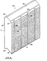
- the insulated siding structure as shown in Figure 1 comprises a hardboard panel 10 laminated to a layer 11 of rigid foam plastic material.
- the hardboard panel 10 can be for example one foot in height and up to sixteen feet in length for application as the siding to the outside of a building.
- the hardboard panel can be for example 3/8 inch thick and of conventional construction.
- the top edge of the panel indicated at 12 is mitered from the outer face toward the inner face adjacent the layer 11 at an angle of the order of 30°.
- the lower edge indicated at 13 is formed by a rounded surface which may be half round or merely have chamfered edges so as to provide a pleasing appearance and to avoid sharp corners which can be easily damaged or 14 chipped.
- the outer face of the panel 10 is coated in a baked paint finish which includes the lower surface 13 and terminates at the upper surface 12.
- an elongate slot 15 which receives a plastic strip 16 along the full length of the panel.
- the angle of the slot and therefore of the strip is the same as the upper surface 12 so they lie parallel with the strip 16 inclined downwardly relative to the inside surface of the panel.
- the foamed plastic insulation layer 11 comprises preferably a polystyrene foam which is relatively rigid and which can be formed in layers of the order of three or four inches thick for lamination to the panel 10.
- the foam is formed by a suitable molding process into the shape illustrated in Figures 1 and 3. It will be appreciated that in Figure 3 the foam layer 11 is inverted and viewed from the other side.
- the foam layer has a front face 17 and a rear face 18 which are parallel and flat.
- the upper surface of the layer is formed from two flat faces 19 and 20 which together form a V-shaped channel.
- the angle of the surface 19 to the front face 17 is the same angle as the angle of the upper surface 12 of the panel 10 so that when attached to the panel the surface 12 and 19 are effectively contiguous.
- the dimension of the surface 19 extending from the front face 17 towards the rear face 18 is of the order of 2/3 of the thickness of the layer that is approximately two inches in a layer of three inch thickness.
- the surface 20 is inclined relative to the rear face 18 at the same angle as the surface 19 so that the edge 21 between the surface 20 and the rear face 18 is at a lower height than the edge 22 between the surface 19 and the front face 17.
- the lower face 23 of the layer 11 is again divided into two surfaces 24 and 25 which are parallel and of equal dimension to the surfaces 19 and 20 respectively.--The dimensions and angle of the surface 24 are arranged such that the surface commences on the upper side of the strip 16 and extends downwardly to an edge 26 between the surface 24 and the surface 25 such that the edge 26 lies in the same horizontal plane as or slightly above the lower surface 13 of the panel 10.
- the surface 24 has a first channel 27 recessed therefrom adjacent the inner face 17 and extending along the full length of the layer 11. As shown in Figure 1, this channel or recess 27 is effectively rectangular in shape and is arranged adjacent the strip 16 so the strip 16 extends into the channel 27 but does not close it leaving a channel extending along the full length of the layer 11 adjacent the strip 16.
- a plurality of rectangular channels 29 is provided recessed into the front face 17 and extending substantially vertically down the front face from the upper surface 19 to the channel 27 in the lower surface 24. The upper end of the channels 29 is visible in Figure 1.
- the lower end of the channel 29 is flared as at 28 so as to accommodate any ice which may form in moisture collecting at the bottom of the channel 29.
- the front face 17 of the layer is roughened for example by engagement with a pinned wheel to form a suitable surface for adhesion to the panel 10.
- a layer of adhesive for example a foamed moisture-proof adhesive is then 110 applied to the rear surface of the panel 10 for attachment of the layer 11.
- the rear surface of the panel can also be painted or otherwise coated at least at the lower edge which is exposed in order to prevent the entry of moisture. Suitable adhesive will of course be well known to one skilled in the art.
- the recessed channels 29 therefore do not contact the rear surface of the panel 10 and therefore remain as channels passing between the panel and the front face 17 of the layer 11.
- the position of the layer relative to the panel is arranged such that the upper surface 19 is contiguous with the surface 12 while the lower surface 24 just contacts the upper edge of the strip 16 leaving a section 161 free from the foam layer.
- channels 27 and 29 provide a communication system for vapor and gases through the panel from the top to the bottom and also along the panel.
- edges 25 and 21 which constitute the uppermost and lowermost edges of the foam layer 11 are within the confines of the upper edge and lower edge of the panel 10 and thus are effectively protected by the solid panel 10 and can be stacked and packaged without damage.
- the hardboard layer 10 is protected by a moisture vapor barrier formed by the adhesive and/or coating on the rear surface and by a baked on paint finish on the front surface. Effectively therefore, moisture cannot penetrate into the hardboard layer and is confined to running down the outer face or the inner face through the channels 29.
- the front and rear faces of the insulated siding formed by the front face of the panel 10 and the rear face 18 of the layer 11 are parallel thus enabling ready packaging of a number of the sidings in rectangular structure.
- an angle bracket 40 is attached to the wall to be covered by nails 41.
- the bracket 40 extends along the the full length of the intended panel.
- a triangular foam piece is then inserted as indicated at 42 to fill the space beneath the surface 25.
- the angle of the support arm 43 of the bracket is arranged so that it lies coincident with the surface 24.
- a lowermost siding is applied to the flat outer face of a building.
- the outer face of the building is indicated at 30 and including a vertical stud 31 forming a framework for the building.
- the outer face 30 may be formed by some form of paneling or may be the original siding of the building or may comprise just the studs 31 with an intervening insulation layer.
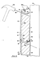
- a first insulated siding indicated at 101 is attached to the outer face.
- the fastening for the sidings can be for example spikes or nails which are simply hammered into the stud 31 at a position adjacent the upper edge of the siding.
- a spacer member 34 is positioned between the outer surface 30 of the building, the upper surface of the siding and the top inner edge of the panel 10.
- the spacer 34 comprises a rigid body with the lower surface shaped including a lip 34A to fit into the space defined by those surfaces and extending along a length of the siding.
- the length could be of the order of four feet so that the spacer bridges a number of studs 31 and provides a straight line regardless of any misalignment of one or two of the studs 31.
- the spacer 34 thus accurately spaces the rear surface of the panel 10 relative to the surface 30 regardless of any force applied to the front surface of the panel by the spike 32 or the hammer 33.
- the position of the spike is arranged such that when the next above panel is applied on top of the first panel the overhang portion indicated at 35 in Figure 2 covers the head of the spike as well as the other . edge of the panel 10.
- the spike is then angled slightly downwardly so as to pass through the foam below the upper surface and through the rear face 18 of the foam into the stud 31.
- the panel 10 of the siding overlies the panel 10 of the lower siding and extends slightly in front thereof so that the upper edge 12 of the panel of the lower side engages the strip 16 of the upper siding.
- the upper surface of the foam layer 11 engages the lower surface of the foam 11 of the upper side thus forming an interlock.
- the lower surface 25 is spaced from the upper surface 20 by a distance approximately equal to the thickness of the panel 10.
- the rear face 18 of the layer 11 is spaced from the front face 30 of the building again by a distance equal to the thickness of the panel 10 with the rear face 18 then inclined rearwardly towards the building so that it contacts the outer face of the building substantially in line contact with the top edge of the rear surface 18 indicated at 36.
- the space between the surfaces 25 and 20 is completely filled with a sponge or flexible foam layer 37 which acts to prevent the passage of air through between the panels.
- the sponge strip 37 is shaped so that it completely fills the space beneath the surface 25 and it turns upwardly in L-shape along the back of the panel to form an L-shape in cross-section. Thus the sponge strip contacts the full extent of the surface 20 and part of the surface 19.
- the sponge strip 42 beneath the lowermost panel is triangular shaped in order to completely fill in a similar manner the space beneath the surface 25 bearing in mind that the angle bracket 40 does not include the upwardly inclined surface 20 in view of the difficulty of manufacture of a bracket of that shape.
- the sponge 37 can either be supplied on site for installation as part of one of the panels that is adhered to either the surface 20 or the surface 25 or it can be supplied as a separate item for introduction during the assembly.
- the spacer 34 includes a handle or handles 38 on its upper surface so that it can be readily lifted away from the installed panel so the next above panel can be placed in position as shown in Figure 2.
- the channels 29 can be arranged so they are lined between one siding and the next above siding but this is not essential in view of the channel 27 which extends across all the channels 29 thus effectively forming a communicating network of channels which allow the moisture to escape.
- the spline or strip 16 takes some of the weight or forces between the two adjacent sidings and therefore tends to form an airtight seal between the top of one panel and the next adjacent panel. Other parts of the weight are taken by the spike 32 and yet further parts by the interconnection between the foam layers 11. The whole structure, therefore, provides an interlocking system which provides structural strength for the building rather than applying weight to the building and therefore the siding can be applied to any building without concern for its withstanding additional forces.
- the adhesive layer between the panel 10 and the foam 11 can be applied with a comb-like object thus providing horizontal ridges in the adhesive. These ridges can to some extent provide a plurality of closely spaced horizontal moisture vapor transmission channels to yet further add to the network of moisture communication channels throughout the siding.
- the hardboard panel 10 can be replaced by an aluminum sheet with interlocking clip arrangements thus providing an overlapping system similar to that shown in Figures 2 and 4.
- the present invention therefore, provides a new construction material which is relatively inexpensive to manufacture and inexpensive to apply to a building. It can be quickly and easily installed by relatively unskilled labour. It provides a wall covering that affords excellent thermal and acoustic insulation. It overcomes the mechanical and physical disadvantages of conventional plastic foam boards. It provides an effective air seal while allowing the transmission of moisture.through a communication network within and between each-panel. It provides an effective interconnection technique between each siding and the next adjacent siding.
- the foam insulation material provides a continuous layer which interconnects one with the next to minimize thermal bridging which can occur where wood and metal members of a structure are interconnected. It provides a very high insulating value which can be of the order of R-15 or greater.
- the overlapping edge between the panels 10 adequately protects the joins against infiltration of water.
- Hardboard sheets with a thickness of at least 3/8 inch are preferred because hardboard has acceptable stiffness, low moisture content with minimum expansion and acceptable weight to strength ratios. It is also readily available and relatively cheap.
- Polystyrene foam is the preferred foam insulation layer and this can be of the type manufactured under the trade mark STYRO-FOAM SM which exhibits very low thermal conductivity over a very long time span.
- the arrangement of the nail 32 parallel to the surface 19 that is inclined downwardly at an angle enables the siding panel to be firmly attached to the building.
- the downward direction initially provides a pulling force on the panel downwardly against the next adjacent lower panel so as to hold the panels as tight as possible against one another.
- the panel in order for the panel to become loose by riding up away from the next adjacent lower panel, it has to bend the nail which in turn reduces the distance between the head of the nail and the outer surface of the building thereby squeezing the upper edge of the panel.
- the forces on the panels work together to hold the panels in place and to hold the hardboard panel against the foam insulation layer.
Landscapes
- Engineering & Computer Science (AREA)
- Architecture (AREA)
- Civil Engineering (AREA)
- Structural Engineering (AREA)
- Physics & Mathematics (AREA)
- Acoustics & Sound (AREA)
- Electromagnetism (AREA)
- Finishing Walls (AREA)
- Building Environments (AREA)
- Laminated Bodies (AREA)
Applications Claiming Priority (2)
| Application Number | Priority Date | Filing Date | Title |
|---|---|---|---|
| CA000459473A CA1250125A (fr) | 1984-07-23 | 1984-07-23 | Panneau de parement, isole, et methode de pose connexe |
| CA459473 | 1984-07-23 |
Publications (2)
| Publication Number | Publication Date |
|---|---|
| EP0170342A2 true EP0170342A2 (fr) | 1986-02-05 |
| EP0170342A3 EP0170342A3 (fr) | 1987-06-03 |
Family
ID=4128365
Family Applications (1)
| Application Number | Title | Priority Date | Filing Date |
|---|---|---|---|
| EP85300888A Withdrawn EP0170342A3 (fr) | 1984-07-23 | 1985-02-11 | Bardage isolé et méthode pour son application |
Country Status (5)
| Country | Link |
|---|---|
| EP (1) | EP0170342A3 (fr) |
| JP (1) | JPS6164948A (fr) |
| KR (1) | KR860001262A (fr) |
| AU (1) | AU4480585A (fr) |
| CA (1) | CA1250125A (fr) |
Cited By (2)
| Publication number | Priority date | Publication date | Assignee | Title |
|---|---|---|---|---|
| DE19703874A1 (de) * | 1997-02-03 | 1998-08-06 | Bierbach Gmbh & Co Kg Befestig | Außenwand |
| US10316515B2 (en) | 2016-01-29 | 2019-06-11 | Owens Corning Intellectual Capital, Llc | Structural insulated sheathing |
Families Citing this family (2)
| Publication number | Priority date | Publication date | Assignee | Title |
|---|---|---|---|---|
| CN112922249A (zh) * | 2017-11-09 | 2021-06-08 | 包头市山川圣阳热能科技有限公司 | 一种可发热的仿木墙裙板制作方法 |
| CN112376762A (zh) * | 2020-11-23 | 2021-02-19 | 中铁十四局集团建筑工程有限公司 | 一种安全可靠节能的框架玻璃幕墙系统及组装方法 |
Family Cites Families (7)
| Publication number | Priority date | Publication date | Assignee | Title |
|---|---|---|---|---|
| US1832397A (en) * | 1930-10-20 | 1931-11-17 | Victor J Hultquist | Tile |
| US3826054A (en) * | 1972-05-15 | 1974-07-30 | B Culpepper | Building insulation and sheathing |
| DE2623355A1 (de) * | 1976-05-25 | 1977-12-08 | Paul Kaiser | Fassadenplatte |
| DE2831284A1 (de) * | 1978-07-17 | 1980-01-31 | Plein Karl Josef | Wandverkleidung, vorzugsweise waerme schutzverkleidung |
| US4292776A (en) * | 1979-08-13 | 1981-10-06 | Macdonald Milton | Unitary combined backer and siding board |
| FR2542350B1 (fr) * | 1983-03-07 | 1985-10-31 | Smac Acieroid | Veture a lame d'air ventilee |
| FR2546560A1 (fr) * | 1983-05-25 | 1984-11-30 | Miplacol | Panneaux pour le revetement de la face externe de parois de batiments |
-
1984
- 1984-07-23 CA CA000459473A patent/CA1250125A/fr not_active Expired
-
1985
- 1985-02-11 EP EP85300888A patent/EP0170342A3/fr not_active Withdrawn
- 1985-07-11 AU AU44805/85A patent/AU4480585A/en not_active Abandoned
- 1985-07-20 KR KR1019850005198A patent/KR860001262A/ko not_active Withdrawn
- 1985-07-23 JP JP60161346A patent/JPS6164948A/ja active Pending
Cited By (3)
| Publication number | Priority date | Publication date | Assignee | Title |
|---|---|---|---|---|
| DE19703874A1 (de) * | 1997-02-03 | 1998-08-06 | Bierbach Gmbh & Co Kg Befestig | Außenwand |
| DE19703874C2 (de) * | 1997-02-03 | 2002-11-07 | Bierbach Gmbh & Co Kg Befestig | Außenwand |
| US10316515B2 (en) | 2016-01-29 | 2019-06-11 | Owens Corning Intellectual Capital, Llc | Structural insulated sheathing |
Also Published As
| Publication number | Publication date |
|---|---|
| EP0170342A3 (fr) | 1987-06-03 |
| AU4480585A (en) | 1986-01-30 |
| CA1250125A (fr) | 1989-02-21 |
| JPS6164948A (ja) | 1986-04-03 |
| KR860001262A (ko) | 1986-02-24 |
Similar Documents
| Publication | Publication Date | Title |
|---|---|---|
| US4586304A (en) | Insulated siding and method for its application | |
| US3159943A (en) | Composite building siding | |
| CA1133224A (fr) | Element de type bardeau pour le batiment | |
| US5836135A (en) | Drainage track | |
| CA2267000C (fr) | Revetement de vinyle renforce | |
| US7934352B1 (en) | Grooved foam backed panels | |
| US4034528A (en) | Insulating vinyl siding | |
| US4320613A (en) | Profiled insulating underboard | |
| US4176504A (en) | Weather proof sandwich panel floor attachment device | |
| US8795813B2 (en) | Ribbed backed panels | |
| US20110296781A1 (en) | Insulating finishable panel | |
| US20160168846A1 (en) | Bracket, a building module, a method for making the module, and a method for using the module to construct a building | |
| US4567701A (en) | Prefabricated panel for a post and sill panelized log wall system | |
| US10995497B1 (en) | Furring and flashing strip system | |
| US20120285109A1 (en) | Siding having backer | |
| US1976947A (en) | Wall veneer | |
| US8336269B1 (en) | Siding having facing and backing portion with grooved and ribbed backing portion surface | |
| EP0170342A2 (fr) | Bardage isolé et méthode pour son application | |
| US20130167456A1 (en) | Building module, a method for making same, and a method for using same to construct a building | |
| JPH0330482Y2 (fr) | ||
| US5165211A (en) | Aluminum covered polystyrene roof tile and method of application to a roof | |
| CN85108643A (zh) | 绝缘墙板及其使用方法 | |
| JPS609317Y2 (ja) | モルタル壁クラック防止下地構造 | |
| JPH0415472Y2 (fr) | ||
| JPS609623B2 (ja) | 外囲体 |
Legal Events
| Date | Code | Title | Description |
|---|---|---|---|
| PUAI | Public reference made under article 153(3) epc to a published international application that has entered the european phase |
Free format text: ORIGINAL CODE: 0009012 |
|
| AK | Designated contracting states |
Designated state(s): AT BE CH DE FR GB IT LI LU NL SE |
|
| PUAL | Search report despatched |
Free format text: ORIGINAL CODE: 0009013 |
|
| AK | Designated contracting states |
Kind code of ref document: A3 Designated state(s): AT BE CH DE FR GB IT LI LU NL SE |
|
| STAA | Information on the status of an ep patent application or granted ep patent |
Free format text: STATUS: THE APPLICATION IS DEEMED TO BE WITHDRAWN |
|
| 18D | Application deemed to be withdrawn |
Effective date: 19871204 |