EP0170543A1 - Mechanische und elektrische Montagevorrichtung für hochintegrierte, elektronische Computer-Leiterplatten - Google Patents
Mechanische und elektrische Montagevorrichtung für hochintegrierte, elektronische Computer-Leiterplatten Download PDFInfo
- Publication number
- EP0170543A1 EP0170543A1 EP85401127A EP85401127A EP0170543A1 EP 0170543 A1 EP0170543 A1 EP 0170543A1 EP 85401127 A EP85401127 A EP 85401127A EP 85401127 A EP85401127 A EP 85401127A EP 0170543 A1 EP0170543 A1 EP 0170543A1
- Authority
- EP
- European Patent Office
- Prior art keywords
- connectors
- receptacle
- cards
- connector
- card
- Prior art date
- Legal status (The legal status is an assumption and is not a legal conclusion. Google has not performed a legal analysis and makes no representation as to the accuracy of the status listed.)
- Granted
Links
- 238000003780 insertion Methods 0.000 claims abstract description 18
- 230000037431 insertion Effects 0.000 claims abstract description 18
- 230000010354 integration Effects 0.000 claims abstract description 13
- 230000001681 protective effect Effects 0.000 claims abstract description 3
- 230000002787 reinforcement Effects 0.000 claims description 4
- 239000002184 metal Substances 0.000 abstract description 5
- 238000000429 assembly Methods 0.000 description 6
- 238000005516 engineering process Methods 0.000 description 5
- 230000015654 memory Effects 0.000 description 5
- 238000010586 diagram Methods 0.000 description 4
- 238000002513 implantation Methods 0.000 description 3
- 239000000758 substrate Substances 0.000 description 3
- 230000007613 environmental effect Effects 0.000 description 2
- 230000006870 function Effects 0.000 description 2
- 239000004593 Epoxy Substances 0.000 description 1
- 230000006399 behavior Effects 0.000 description 1
- 239000000919 ceramic Substances 0.000 description 1
- 238000001816 cooling Methods 0.000 description 1
- 230000000694 effects Effects 0.000 description 1
- 239000011521 glass Substances 0.000 description 1
- 230000017525 heat dissipation Effects 0.000 description 1
- 238000002347 injection Methods 0.000 description 1
- 239000007924 injection Substances 0.000 description 1
- 238000009434 installation Methods 0.000 description 1
- 229910001234 light alloy Inorganic materials 0.000 description 1
- 238000012423 maintenance Methods 0.000 description 1
- 238000004519 manufacturing process Methods 0.000 description 1
- 238000000034 method Methods 0.000 description 1
- 238000000465 moulding Methods 0.000 description 1
- 239000008188 pellet Substances 0.000 description 1
- 239000004576 sand Substances 0.000 description 1
- 238000000926 separation method Methods 0.000 description 1
- 230000035939 shock Effects 0.000 description 1
- 238000009423 ventilation Methods 0.000 description 1
Images


Classifications
-
- H—ELECTRICITY
- H05—ELECTRIC TECHNIQUES NOT OTHERWISE PROVIDED FOR
- H05K—PRINTED CIRCUITS; CASINGS OR CONSTRUCTIONAL DETAILS OF ELECTRIC APPARATUS; MANUFACTURE OF ASSEMBLAGES OF ELECTRICAL COMPONENTS
- H05K7/00—Constructional details common to different types of electric apparatus
- H05K7/14—Mounting supporting structure in casing or on frame or rack
- H05K7/1422—Printed circuit boards receptacles, e.g. stacked structures, electronic circuit modules or box like frames
- H05K7/1424—Card cages
-
- H—ELECTRICITY
- H05—ELECTRIC TECHNIQUES NOT OTHERWISE PROVIDED FOR
- H05K—PRINTED CIRCUITS; CASINGS OR CONSTRUCTIONAL DETAILS OF ELECTRIC APPARATUS; MANUFACTURE OF ASSEMBLAGES OF ELECTRICAL COMPONENTS
- H05K7/00—Constructional details common to different types of electric apparatus
- H05K7/20—Modifications to facilitate cooling, ventilating, or heating
Definitions
- the invention relates to the field of the production of complex computer systems, and more particularly to a high density mechanical and electrical assembly device suitable for the interconnection of highly integrated electronic cards, in particular in harsh environments.
- connection points is the order of magnitude necessary for these types of technologies.
- Another format used for civil applications, for a 32-bit DLX calculator for example, is the so-called "double europe" format in which the cards have dimensions of 320 mm x 320 mm, and which each have four 96-point connectors, two on each of two parallel edges. Cards having this format do not allow to withstand severe environmental constraints, for example those imposed for military systems.
- the connectors of electronic cards in CEN format are connected by means of connectors called "backplane" placed on a support, the cards sliding in orthogonal slides at the bottom of the receptacle basket.
- the card connectors and the backplane connectors face each other as soon as the card is positioned in the basket.
- the connectors arranged on the opposite edge of the card, for cards in the double europe format are connected by the front face, the interconnection with the external environment being thus effected by the front face.
- the spacing of the connection points in these 96-pin connectors is 2.54 mm, the standard spacing of the cards in the basket being either 12.7 mm or 7.62 mm.
- the evacuation of calories is generally provided in the frame forming the mechanical framework of the card, the shape of which is adapted to the necessary dissipation.
- the subject of the invention is a mechanical and electrical assembly device for high integration computer electronic cards which makes it possible to solve these problems in a "small" conventional format compatible with mechanical integration in a 1/2 ATR or 3/4 box.
- ATR for example.
- it uses high density connectors, for example 200 points, with zero insertion force, associated with locking means and with a particular receptacle.
- a mechanical and electrical assembly device for highly integrated electronic computer cards comprises a one-piece receptacle shaped U-shaped in the bottom of which is provided at least one slot, and in the walls lateral of which are provided recesses each receiving at least one multicontact connector, the contacts of which are distributed along the card insertion slot in the connector, this connector having - zero insertion force and being associated with a device for locking-unlocking, this receptacle being intended for the connection of electronic cards having spaced contact tracks like the contacts of the connectors, on at least one face of the card and on two opposite sides and comprising a thermal connector on a third side placed, in locked position, in the corresponding slot at the bottom of the receptacle, the bottom of the receptacle forming heat exchanger backsplash.
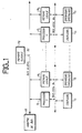
- FIG. 1 there is shown a multi-processor and multi-bus system for understanding the advantage of the assembly device according to the invention.
- This system includes 16 or 32 bit processors, P 1 ... P n with which local memories M 1 ... M n are associated.
- a certain number of couplers C 1 ... C n are associated respectively with each of the processors P 1 ... P n , as well as specialized operators 0 1 ... 0 n .
- index i, i 1 to n
- the processor P., the memory M i , the couplers Ci, and the specialized operators 0. are interconnected via a local bus B.
- these sub-assemblies are interconnected with one another via a global bus BG, 1 associated with a global memory MG; a bus arbitration circuit, AR, is provided to govern the exchanges between the sub-assemblies.
- the global bus with power connections must have approximately 200 points; each central processor unit or local memory is connected to the global bus by approximately 100 points.
- the outputs of processors, local memories, couplers, or specialized operators are also made by sets of 100 points, like the inputs outputs. Consequently, it is advantageous to provide suitable assembly systems, allowing the possible integration of several functions on the same card with a high integration density, the assembly system comprising around 400 connection points. to connect a card to the global bus of a system as well as to the local buses of different sub-assemblies.
- the mechanical and electrical assembly device consists of a receptacle with which motherboards are associated with possible protection means suitable for the interconnection of plug-in electronic elements, or cards, including the contact points and thermal connectors are organized in a particular way, as will be described below.
- FIG. 2 An elementary receptacle of the electrical assembly device according to the invention is shown in FIG. 2.
- This receptacle 10 is intended to receive, maintain and interconnect a pluggable electronic element, by means of two connectors with zero insertion force.
- This receptacle 10 consists of a U-shaped metal profile, the dimensions of which, length of the branches 1, height of the bottom h and width e are adapted to the standard used.
- This receptacle is made of light alloy, AG4 for example, by molding techniques of the sand, shell, lost wax, or injection type.
- Each branch of the U has a rectangular recess, receiving a connector 30, with 200 contacts and zero insertion force.
- the slot of the connector is extended to the ends of the branches of the U so that the insertion of the plug-in electronic element is made by sliding in the slots, parallel to the branches.
- a slot 50 is also provided in the bottom of the receptacle, and is intended to receive a thermal connector provided in the plug-in electronic element.
- the thickness E of the bottom of the U is sufficient for this receptacle to perform the function of thermal backsplash.
- the connectors with zero insertion force therefore comprise 100 contacts on each side of the connector, spaced 1.27 mm apart, face to face or alternated.
- the terminations 32, orthogonal to the connector are alternated in steps of 1.27 mm. These terminations are tinned and of the type to be soldered on a printed circuit.
- the zero insertion force connectors 30 each have 200 contacts as indicated above, at a spacing of 1.27 mm, and operate as follows: each connector has two positions for the contacts and is controlled by a device locking-unlocking 31.
- the connector When inserting the plug-in electronic element into the slots of the receptacle and of the connector, the connector is in the open position, its contacts being erased in slots of the connector and, no force is applied to the contact track of the plug-in electronic element
- the locking-unlocking device 31 allows the contacts to come out of their housings to apply them to the corresponding tracks of the card files, also in 1.27 mm steps. The contacts are then locked in this position.
- the passage from the open position to the closed position is effected by a locking-unlocking system 31 accessible at the end of each branch of the receptacle by suitable tools.
- FIG. 3 represents the assembly device system according to the invention, with a multi-card receptacle.
- the receptacle 10 is intended to receive, maintain, and interconnect, a set of pluggable electronic elements or electronic cards using connectors with zero insertion force.
- the receptacle itself consists of a metal profile, the section of which is U-shaped and the length of which is designed to receive a certain number of cards.
- Each side wall associated with a branch of the U is intended to receive connectors with 200 contacts at zero insertion force, and, as described above, the bottom of the U is reserved for thermal evacuation.
- the walls corresponding to the branches of the profiled U are hollowed out to each receive a set of connectors.
- These connectors can be interconnected by means of a wiring circuit for each side wall, for example a motherboard, 20 and 21 respectively, previously soldered to the wave at these connectors.
- These motherboards 20 and 21 are printed circuits allowing direct interconnections between cards arranged in the same multi-card receptacle.
- the spacing between the cards provided being the standard spacing 12.7 mm and the width of the connectors also being close to 12.7 mm, the recess 40 of the receptacle for positioning connectors soldered to the motherboard 20 or 21 is produced in one go over the entire length of the receptacle, this to avoid overlapping several tolerances as to positioning.
- the connectors 30 protrude from the receptacle, and their insertion slot is therefore accessible inside the U, without having to make a slot in the receptacle 10.
- the bottom of the metal profile 10 forming the receptacle comprises slots 50 spaced 12.7 mm apart, into which thermal connectors provided on one of the edges of the electronic cards can be inserted.
- Supply reinforcement bars 60 can be provided and welded on the face of the motherboard opposite to that carrying the connectors, and over the entire length of the profile.
- the receptacle is provided with a locking-unlocking device 31 formed by a locking-unlocking element associated with each connector 30, and arranged along the receptacle.
- This receptacle 10 which forms the framework of the assembly device according to the invention can be supplemented by a covering which makes it possible to protect the mother cards as well as the daughter cards inserted in the receptacle.
- metallic protective covers 70 and 71 are provided for the two motherboards carrying the connectors. They are fixed to the receptacle 10 via the reinforcement bars 60 and the edges of the motherboards. These covers can be made airtight.
- the ends of the U-shaped receptacle profile can be closed in the case of use in a bay by flanges, or in the case of a direct use by panels, 72 and 73 in FIG. 3 for example, one possibly being provided with an operational console applied at one end and the other carrying the external interconnection sockets at the other end .
- the face of the receptacle left free for the introduction of the cards is closed by a plate 74 bearing on backsplashes provided on the fourth side of the cards to provide additional thermal conduction to the outside.
- Such a structure makes it possible to provide that all the supply and global bus connections will be provided on one of the side walls of the U-shaped receptacle, the global bus output being provided for example in such a connection device by means of 'a high density connector on the upper motherboard reserved for this purpose, in which no electronic card is plugged in and to which a screened ribbon cable 80 is connected.
- the connection between the various connectors is made directly via the motherboard 21 in printed circuit for the interconnection between cards carried by the same receptacle.
- Shielded ribbon cables 81, 82, 83 for example can be provided and connected to some of the high density connectors to make the input / output connections.
- the backrest of the receptacle, that is to say the bottom of the U, receiving the thermal connectors of the cards is the natural thermal radiator in this technology.
- the heat exchanges can be carried out at this level either by natural convection, or by conduction (the backsplash of the receptacle being fixed on a heat exchanger, or a heat pipe, or an exchanger with pellet effect etc.), or by forced convection , the backsplash can be opened to allow the passage of forced ventilation.
- the upper motherboard, associated with the global bus can also allow, as indicated above, to distribute the power on the connectors of the upper part.
- This global bus motherboard can be produced by multilayer printed circuit. The possible connection of this bus to the outside is provided by metallized holes at the end of the cards allowing the connection ment of a printed tablecloth.
- the local bus motherboard is adapted to each application.
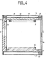
- FIG. 4 shows in section the mechanical electrical assembly device according to the invention in which an electronic card has been inserted.
- the card 100 includes a central useful zone, a thermal connector 55 for insertion into a slot 50 of the backsplash of the receptacle, two files of 200 points each located in two zones of the card 35 located on two opposite sides and constituting the guide zone: the connection tracks are deposited by photoengraving, in steps of 1.27 mm.
- the two side walls of the device are symmetrical but the connector part 30 is shown at the top of FIG. 4 and the card part with its contact tracks in the area 35 at the bottom of the figure.
- the overall dimensions of the card can be 80 mm x 190 mm.
- This card format allows the implantation by face of 30 conventional 14 or 16 pin boxes, or 60 boxes of the "chip carrier" type, or even 100 to 120 hybridized chips.
- a format compatible with mechanical integration in a 3/4 ATR box that is to say 145 x 190 mm, such a card allows the implantation by face of 60 14 or 16 pin converter boxes, or 120 chip type boxes carrier.
- This format also allows the implantation of hybridized chips by means of suitable supports.
- the dissipated powers envisaged can be of the order of 20 watts for a ceramic substrate, 15 watts for a colaminated substrate, or 10 watts for a substrate in epoxy glass.
- the invention is not limited to the embodiments described and shown.
- the value indicated for the pitch of the connectors 1.27 mm, was chosen to be half the usual pitch 2.54 mm.
- this value is not limiting and neighboring values making it possible to keep the same order of magnitude for the number of connection points could also be chosen.
- the number of connection points, 400 is not limiting. It was indicated to allow to keep a few additional connection points in addition to the points necessary in a 32-bit system.
- the connectors described, having contacts of each side of the insertion slot are suitable for double-sided cards. However, connectors suitable for single-sided cards, comprising contacts on one side of the insertion slot can also be used.
- the thermal connector can also be used to increase, beyond 400 points, the connection capacity of an electronic card (for example bus power supply, electrical and mechanical masses etc ).
- the mechanical and electrical assembly device has been described above as comprising as many connectors as the recess provided for in the side walls of the receptacle can contain.
- this configuration can be adapted to the configuration of the application, and some of the connectors provided for the elementary spacing can be eliminated, for example when a sub-assembly is wired in double thickness and occupies two elementary spaces. It would also be possible to maintain mechanically a sub-assembly comprising two cards to provide a connector in which the electrical contacts are not used.
- the mechanical and electrical assembly device according to the invention which simultaneously provides the mechanical strength and the electrical connections, is particularly well adaptable, because of the possibility of physical separation of the wiring between the global bus and the local buses, and the makes wide possibilities for extension by standardizing the wiring.
- This assembly device can accommodate all types of single or double-sided cards: classic cards with standard components, "Chip carrier” cards, hybrid circuit cards, or cards using components from different technologies.
Landscapes
- Engineering & Computer Science (AREA)
- Microelectronics & Electronic Packaging (AREA)
- Physics & Mathematics (AREA)
- Thermal Sciences (AREA)
- Coupling Device And Connection With Printed Circuit (AREA)
- Mounting Of Printed Circuit Boards And The Like (AREA)
Applications Claiming Priority (2)
| Application Number | Priority Date | Filing Date | Title |
|---|---|---|---|
| FR8409308A FR2566221B1 (fr) | 1984-06-14 | 1984-06-14 | Dispositif d'assemblage mecanique et electrique pour cartes electroniques informatiques a haute integration |
| FR8409308 | 1984-06-14 |
Publications (2)
| Publication Number | Publication Date |
|---|---|
| EP0170543A1 true EP0170543A1 (de) | 1986-02-05 |
| EP0170543B1 EP0170543B1 (de) | 1988-09-14 |
Family
ID=9305004
Family Applications (1)
| Application Number | Title | Priority Date | Filing Date |
|---|---|---|---|
| EP85401127A Expired EP0170543B1 (de) | 1984-06-14 | 1985-06-07 | Mechanische und elektrische Montagevorrichtung für hochintegrierte, elektronische Computer-Leiterplatten |
Country Status (9)
| Country | Link |
|---|---|
| US (1) | US4731698A (de) |
| EP (1) | EP0170543B1 (de) |
| JP (1) | JPS6122583A (de) |
| CA (1) | CA1223083A (de) |
| DE (1) | DE3565036D1 (de) |
| DK (1) | DK262885A (de) |
| FR (1) | FR2566221B1 (de) |
| MX (1) | MX158352A (de) |
| NO (1) | NO852421L (de) |
Families Citing this family (32)
| Publication number | Priority date | Publication date | Assignee | Title |
|---|---|---|---|---|
| IT8535502V0 (it) * | 1985-01-03 | 1985-01-03 | Selenia Ind Elettroniche | Struttura elettromeccanica,atta ad ospitare moduli elettronici,da utilizzare preferenzialmente in ripartitori di centrali telefoniche utilizzanti anche circuiti stampati fprmatp europa |
| US5485351A (en) * | 1989-06-09 | 1996-01-16 | Labinal Components And Systems, Inc. | Socket assembly for integrated circuit chip package |
| US5282111A (en) * | 1989-06-09 | 1994-01-25 | Labinal Components And Systems, Inc. | Thermal transfer plate and integrated circuit chip or other electrical component assemblies including such plate |
| US5051096A (en) * | 1989-10-23 | 1991-09-24 | International Business Machines Corp. | Planar board support structure |
| JPH0773590B2 (ja) * | 1990-05-17 | 1995-08-09 | 武平 赤羽 | 義 歯 |
| US5454080A (en) * | 1992-02-10 | 1995-09-26 | International Business Machines Corporation | Removable hard disk drive system with circuit for hot insertion and removal responsive to contacts of zero-insertion-force connector on the lateral side of the drive |
| US5280411A (en) * | 1993-05-10 | 1994-01-18 | Southwest Research Institute | Packaging for an electronic circuit board |
| US5700342A (en) * | 1993-06-30 | 1997-12-23 | Simmonds Precision Products Inc. | Composite enclosure for electronic hardware |
| US5520976A (en) * | 1993-06-30 | 1996-05-28 | Simmonds Precision Products Inc. | Composite enclosure for electronic hardware |
| GB9524543D0 (en) * | 1995-11-30 | 1996-01-31 | Amp Great Britain | Interconnection system for electronic controllers to a bus |
| RU2158063C2 (ru) * | 1996-07-23 | 2000-10-20 | ЦНИИ "Электроприбор" | Радиоэлектронный прибор |
| DE19854096A1 (de) * | 1998-11-24 | 2000-05-25 | Merck Patent Gmbh | Anschlußträger für plattenförmige Mikrokomponenten |
| TW417904U (en) * | 1999-05-28 | 2001-01-01 | Hon Hai Prec Ind Co Ltd | Fastening device for expansion card |
| RU2196398C2 (ru) * | 2001-03-11 | 2003-01-10 | Федеральное государственное унитарное предприятие "Центральный научно-исследовательский институт "Морфизприбор" | Пульт управления аппаратуры морской техники |
| US6785138B1 (en) | 2002-09-05 | 2004-08-31 | Added Communications Of Georgia, Inc. | Repeater case for HDSL modules |
| WO2006129350A1 (ja) * | 2005-05-31 | 2006-12-07 | Fujitsu Limited | 通信装置、情報処理装置及び外線ケーブルの接続方法 |
| US7740489B2 (en) | 2008-10-13 | 2010-06-22 | Tyco Electronics Corporation | Connector assembly having a compressive coupling member |
| US7896698B2 (en) * | 2008-10-13 | 2011-03-01 | Tyco Electronics Corporation | Connector assembly having multiple contact arrangements |
| US7867032B2 (en) * | 2008-10-13 | 2011-01-11 | Tyco Electronics Corporation | Connector assembly having signal and coaxial contacts |
| US8113851B2 (en) * | 2009-04-23 | 2012-02-14 | Tyco Electronics Corporation | Connector assemblies and systems including flexible circuits |
| US7789669B1 (en) | 2009-04-23 | 2010-09-07 | Tyco Electronics Corporation | Removable card connector assemblies having flexible circuits |
| US8215964B2 (en) * | 2010-01-13 | 2012-07-10 | Tyco Electronics Corporation | Connectors and assemblies having a plurality of moveable mating arrays |
| US8282290B2 (en) | 2010-01-13 | 2012-10-09 | Tyco Electronics Corporation | Connectors and assemblies having a plurality of moveable mating arrays |
| US7789668B1 (en) | 2009-04-23 | 2010-09-07 | Tyco Electronics Corporation | Connector assemblies and systems including flexible circuits |
| US7794233B1 (en) | 2009-06-09 | 2010-09-14 | Tyco Electronics Corporation | Flexible circuit member for electrically coupling connectors with one another |
| US8282422B2 (en) | 2009-11-24 | 2012-10-09 | Tyco Electronics Corporation | Electrical connector assembly having a separable mating interface |
| US8033835B2 (en) * | 2009-12-18 | 2011-10-11 | Tyco Electronics Corporation | Interconnect assembly having a separable mating interface |
| US8033852B2 (en) * | 2009-12-23 | 2011-10-11 | Tyco Electronics Corporation | Connector assembly for coupling circuit boards |
| US8221146B2 (en) * | 2010-01-11 | 2012-07-17 | Tyco Electronics Corporation | Linearly actuated connector mating interface |
| US7918683B1 (en) | 2010-03-24 | 2011-04-05 | Tyco Electronics Corporation | Connector assemblies and daughter card assemblies configured to engage each other along a side interface |
| US8292644B2 (en) | 2010-04-09 | 2012-10-23 | Tyco Electronics Corporation | Connector assembly having a floating mating array |
| US8251755B2 (en) | 2010-06-14 | 2012-08-28 | Tyco Electronics Corporation | Connector with a laterally moving contact |
Citations (8)
| Publication number | Priority date | Publication date | Assignee | Title |
|---|---|---|---|---|
| FR2292400A1 (fr) * | 1974-11-20 | 1976-06-18 | Applic Elettro Telefoniche | Dispositif de connexion pour circuits de telecommunication |
| DE2757811A1 (de) * | 1976-12-29 | 1978-07-13 | Fujitsu Ltd | Printplattenaufbau |
| US4214292A (en) * | 1978-11-30 | 1980-07-22 | Sperry Corporation | Printed circuit board guide spring |
| FR2471059A1 (fr) * | 1979-11-29 | 1981-06-12 | Thomson Csf Mat Tel | Connecteur electrique du genre de ceux pour cartes comportant des conducteurs imprimes ou graves ainsi que fiche de connexion electrique enfichable dans un tel connecteur |
| FR2477828A1 (fr) * | 1980-03-07 | 1981-09-11 | Thomson Csf Mat Tel | Systeme d'interconnexion electrique et thermique pour des cartes a circuits electroniques, et armoire electrique equipee d'un tel systeme |
| EP0058759A2 (de) * | 1981-02-25 | 1982-09-01 | Siemens Aktiengesellschaft | Steuergerät in Modulbauweise |
| EP0068195A1 (de) * | 1981-06-12 | 1983-01-05 | COMPAGNIE INDUSTRIELLE DES TELECOMMUNICATIONS CIT-ALCATEL S.A. dite: | Gestell für elektronische Einrichtung |
| US4454566A (en) * | 1981-11-27 | 1984-06-12 | Bell Telephone Laboratories, Incorporated | Heat removal from cabinets housing electronic equipment |
Family Cites Families (8)
| Publication number | Priority date | Publication date | Assignee | Title |
|---|---|---|---|---|
| CA915796A (en) * | 1972-11-28 | I. Shaw Jeffery | Mounting arrangement for electric circuit | |
| US3467891A (en) * | 1967-10-03 | 1969-09-16 | Gen Electric | Combination electrical,mechanical,and thermal connector assembly |
| US3631325A (en) * | 1970-06-15 | 1971-12-28 | Sperry Rand Corp | Card module and end wall treatment facilitating heat transfer and sliding |
| US3992653A (en) * | 1975-08-18 | 1976-11-16 | Sperry Rand Corporation | Zero insertion force card guide |
| SU731623A1 (ru) * | 1976-09-01 | 1980-04-30 | Предприятие П/Я Г-4371 | Радиоэлектронный модуль со сменными платами |
| JPS55123734A (en) * | 1979-03-16 | 1980-09-24 | Sharp Corp | Mode display unit of electronic desk calculator |
| JPS5713990U (de) * | 1980-06-28 | 1982-01-25 | ||
| JPS5913850B2 (ja) * | 1981-08-27 | 1984-04-02 | 株式会社 サアミ | カ−テン装置 |
-
1984
- 1984-06-14 FR FR8409308A patent/FR2566221B1/fr not_active Expired
-
1985
- 1985-06-07 EP EP85401127A patent/EP0170543B1/de not_active Expired
- 1985-06-07 DE DE8585401127T patent/DE3565036D1/de not_active Expired
- 1985-06-10 CA CA000483592A patent/CA1223083A/en not_active Expired
- 1985-06-11 US US06/743,610 patent/US4731698A/en not_active Expired - Fee Related
- 1985-06-12 DK DK262885A patent/DK262885A/da not_active Application Discontinuation
- 1985-06-13 JP JP60129085A patent/JPS6122583A/ja active Pending
- 1985-06-14 NO NO852421A patent/NO852421L/no unknown
- 1985-06-14 MX MX205658A patent/MX158352A/es unknown
Patent Citations (8)
| Publication number | Priority date | Publication date | Assignee | Title |
|---|---|---|---|---|
| FR2292400A1 (fr) * | 1974-11-20 | 1976-06-18 | Applic Elettro Telefoniche | Dispositif de connexion pour circuits de telecommunication |
| DE2757811A1 (de) * | 1976-12-29 | 1978-07-13 | Fujitsu Ltd | Printplattenaufbau |
| US4214292A (en) * | 1978-11-30 | 1980-07-22 | Sperry Corporation | Printed circuit board guide spring |
| FR2471059A1 (fr) * | 1979-11-29 | 1981-06-12 | Thomson Csf Mat Tel | Connecteur electrique du genre de ceux pour cartes comportant des conducteurs imprimes ou graves ainsi que fiche de connexion electrique enfichable dans un tel connecteur |
| FR2477828A1 (fr) * | 1980-03-07 | 1981-09-11 | Thomson Csf Mat Tel | Systeme d'interconnexion electrique et thermique pour des cartes a circuits electroniques, et armoire electrique equipee d'un tel systeme |
| EP0058759A2 (de) * | 1981-02-25 | 1982-09-01 | Siemens Aktiengesellschaft | Steuergerät in Modulbauweise |
| EP0068195A1 (de) * | 1981-06-12 | 1983-01-05 | COMPAGNIE INDUSTRIELLE DES TELECOMMUNICATIONS CIT-ALCATEL S.A. dite: | Gestell für elektronische Einrichtung |
| US4454566A (en) * | 1981-11-27 | 1984-06-12 | Bell Telephone Laboratories, Incorporated | Heat removal from cabinets housing electronic equipment |
Also Published As
| Publication number | Publication date |
|---|---|
| NO852421L (no) | 1985-12-10 |
| DE3565036D1 (en) | 1988-10-20 |
| DK262885D0 (da) | 1985-06-12 |
| FR2566221A1 (fr) | 1985-12-20 |
| DK262885A (da) | 1985-12-15 |
| US4731698A (en) | 1988-03-15 |
| MX158352A (es) | 1989-01-26 |
| EP0170543B1 (de) | 1988-09-14 |
| JPS6122583A (ja) | 1986-01-31 |
| FR2566221B1 (fr) | 1988-03-25 |
| CA1223083A (en) | 1987-06-16 |
Similar Documents
| Publication | Publication Date | Title |
|---|---|---|
| EP0170543B1 (de) | Mechanische und elektrische Montagevorrichtung für hochintegrierte, elektronische Computer-Leiterplatten | |
| EP0196726B1 (de) | Aus stapelbaren Modulen bestehendes elektronisches System | |
| EP2625940B1 (de) | Elektronisches modul, führungsschiene eines derartigen moduls und leiterplatte für den einsatz in ein derartiges modul | |
| CA2343018C (fr) | Dispositif de connexion pour un ensemble de structures modulaires porte-cartes electroniques et rack equipe d'un tel dispositif, accueillant un tel ensemble | |
| US4454566A (en) | Heat removal from cabinets housing electronic equipment | |
| EP0438012A2 (de) | Anordnung für doppelseitige Rückwand | |
| EP1550361B1 (de) | Dreidimensionales elektronisches modul | |
| US4107760A (en) | Dual printed circuit card mount assembly | |
| EP1884149B1 (de) | In schwierigen umgebungen arbeitende modulare elektronische vorrichtung | |
| EP0599678A1 (de) | Anordnung zur Erwärmung von elektronischen Platten | |
| FR2929482A1 (fr) | Calculateur a l'agencement simplifie, destine a l'aeronautique | |
| FR2577102A1 (fr) | Structure de montage pour modules de circuits electroniques | |
| CA2898070A1 (fr) | Systeme de connexion pour cartes de protection d'un systeme de distribution et rack integrant ledit systeme | |
| FR2594603A1 (fr) | Connecteur pour bus informatique | |
| US6831844B1 (en) | Electronic circuit unit providing EMI shielding | |
| FR2579859A1 (fr) | Arrangement de modules de circuits electriques et bati comprenant un tel arrangement | |
| EP0710066B1 (de) | Einschub für elektronische Karten und sein Träger | |
| EP4332728B1 (de) | Computerblade mit versetzten netzwerkkarten | |
| EP0710065B1 (de) | Einschub für elektronische Karten | |
| FR2764473A1 (fr) | Tiroir electronique comportant un dispositif ameliore d'evacuation de chaleur | |
| FR2630859A1 (fr) | Boitier ceramique multicouches a plusieurs puces de circuit-integre | |
| EP3675606A1 (de) | Gedruckter schaltkreis, der einen qsfp-anschluss »belly-to-belly« mit einem qsfp-dd-anschluss ermöglicht, und entsprechendes system | |
| EP4324308B1 (de) | Elektronische verbinder zur verwendung an bord eines raumfahrzeugs | |
| EP3503699B1 (de) | Verbindungssystem von elektronischen karten, und gehäuse für computerberechnungen, das ein solches system umfasst | |
| FR2700069A1 (fr) | Système d'interconnexion de cartes d'un système informatique rapide. |
Legal Events
| Date | Code | Title | Description |
|---|---|---|---|
| PUAI | Public reference made under article 153(3) epc to a published international application that has entered the european phase |
Free format text: ORIGINAL CODE: 0009012 |
|
| AK | Designated contracting states |
Designated state(s): BE DE GB IT NL SE |
|
| 17P | Request for examination filed |
Effective date: 19860606 |
|
| 17Q | First examination report despatched |
Effective date: 19880118 |
|
| RAP1 | Party data changed (applicant data changed or rights of an application transferred) |
Owner name: THOMSON-CSF |
|
| GRAA | (expected) grant |
Free format text: ORIGINAL CODE: 0009210 |
|
| AK | Designated contracting states |
Kind code of ref document: B1 Designated state(s): BE DE GB IT NL SE |
|
| ITF | It: translation for a ep patent filed | ||
| REF | Corresponds to: |
Ref document number: 3565036 Country of ref document: DE Date of ref document: 19881020 |
|
| GBT | Gb: translation of ep patent filed (gb section 77(6)(a)/1977) | ||
| RAP4 | Party data changed (patent owner data changed or rights of a patent transferred) |
Owner name: THOMSON-CSF |
|
| PLBE | No opposition filed within time limit |
Free format text: ORIGINAL CODE: 0009261 |
|
| STAA | Information on the status of an ep patent application or granted ep patent |
Free format text: STATUS: NO OPPOSITION FILED WITHIN TIME LIMIT |
|
| 26N | No opposition filed | ||
| PGFP | Annual fee paid to national office [announced via postgrant information from national office to epo] |
Ref country code: BE Payment date: 19900516 Year of fee payment: 6 |
|
| PGFP | Annual fee paid to national office [announced via postgrant information from national office to epo] |
Ref country code: GB Payment date: 19900518 Year of fee payment: 6 |
|
| PGFP | Annual fee paid to national office [announced via postgrant information from national office to epo] |
Ref country code: DE Payment date: 19900519 Year of fee payment: 6 |
|
| PGFP | Annual fee paid to national office [announced via postgrant information from national office to epo] |
Ref country code: SE Payment date: 19900523 Year of fee payment: 6 |
|
| ITTA | It: last paid annual fee | ||
| PGFP | Annual fee paid to national office [announced via postgrant information from national office to epo] |
Ref country code: NL Payment date: 19900630 Year of fee payment: 6 |
|
| PG25 | Lapsed in a contracting state [announced via postgrant information from national office to epo] |
Ref country code: GB Effective date: 19910607 |
|
| PG25 | Lapsed in a contracting state [announced via postgrant information from national office to epo] |
Ref country code: SE Effective date: 19910608 |
|
| PG25 | Lapsed in a contracting state [announced via postgrant information from national office to epo] |
Ref country code: BE Effective date: 19910630 |
|
| BERE | Be: lapsed |
Owner name: THOMSON-CSF Effective date: 19910630 |
|
| PG25 | Lapsed in a contracting state [announced via postgrant information from national office to epo] |
Ref country code: NL Effective date: 19920101 |
|
| GBPC | Gb: european patent ceased through non-payment of renewal fee | ||
| NLV4 | Nl: lapsed or anulled due to non-payment of the annual fee | ||
| PG25 | Lapsed in a contracting state [announced via postgrant information from national office to epo] |
Ref country code: DE Effective date: 19920401 |
|
| EUG | Se: european patent has lapsed |
Ref document number: 85401127.7 Effective date: 19920109 |