EP0170976B1 - Tête d'impression à aiguilles à assemblage simple - Google Patents
Tête d'impression à aiguilles à assemblage simple Download PDFInfo
- Publication number
- EP0170976B1 EP0170976B1 EP85109239A EP85109239A EP0170976B1 EP 0170976 B1 EP0170976 B1 EP 0170976B1 EP 85109239 A EP85109239 A EP 85109239A EP 85109239 A EP85109239 A EP 85109239A EP 0170976 B1 EP0170976 B1 EP 0170976B1
- Authority
- EP
- European Patent Office
- Prior art keywords
- needle
- group
- guiding
- printing head
- slide
- Prior art date
- Legal status (The legal status is an assumption and is not a legal conclusion. Google has not performed a legal analysis and makes no representation as to the accuracy of the status listed.)
- Expired
Links
Images

Classifications
-
- B—PERFORMING OPERATIONS; TRANSPORTING
- B41—PRINTING; LINING MACHINES; TYPEWRITERS; STAMPS
- B41J—TYPEWRITERS; SELECTIVE PRINTING MECHANISMS, i.e. MECHANISMS PRINTING OTHERWISE THAN FROM A FORME; CORRECTION OF TYPOGRAPHICAL ERRORS
- B41J2/00—Typewriters or selective printing mechanisms characterised by the printing or marking process for which they are designed
- B41J2/22—Typewriters or selective printing mechanisms characterised by the printing or marking process for which they are designed characterised by selective application of impact or pressure on a printing material or impression-transfer material
- B41J2/23—Typewriters or selective printing mechanisms characterised by the printing or marking process for which they are designed characterised by selective application of impact or pressure on a printing material or impression-transfer material using print wires
- B41J2/235—Print head assemblies
- B41J2/25—Print wires
- B41J2/255—Arrangement of the print ends of the wires
Definitions
- the present invention relates to a needle printing head improved for easy assembling.
- Needle printing heads having a modular structure consisting in groups or modules assembled each other are known in the art.
- a typical modular structure is for instance disclosed in US patent n. 4,260,270 which points out the head as constituted by:
- the needle guiding group is constituted by a conical or pyramidal nose internally provided with transversally arranged hollowed diaphragms and supplied, at the cone basis, with a drilled plate and, on the cone top, with a needle guiding ruby.
- Each of the needles is inserted into a corresponding opening in the plate, the diaphragms and the ruby.
- Each of the needles is provided with an impact head.
- a coil spring is inserted on each needle between the impact head and needle guiding group plate.
- the springs When the printing head is assembled, the springs are loaded and the needles kept in a rest position such that the needle printing tip is coplanar to the external side of the guiding ruby at the nose end. However, during the assembling, when the head is not assembled yet, the springs are released and impose to the needle a position such that the needle printing ends get out from the needle guiding ruby and practically prevent the assembling.
- the needles being not guided at the tip, they can stumble over the ruby instead of inserting into it, breaking themselves or displacing the ruby from its housing.
- the assembling is complicated by another problem that is the risk that the needles get out not only from the end ruby but from all their housings.
- the electromagnet group must be placed on the armature retaining group and, eventually, the needle guiding group must be placed on the two previous groups with the nose turned upwards.
- the improved mosaic head object of the present invention which is provided with means for axially move not only one diaphragm at the end of the needle guiding group, that is the plate or the ruby, but a contiguous diaphragm too.
- the head is shown with the nose turned upwards to better evidence, in the following, the assembling problems which must be solved.
- the head comprises a needle guiding group 1, an electromagnet group 2 and an armature retainer group 3.
- the needle guiding group consists of a nose or body 4 elongated in the direction of a longitudinal axis 8, with a generical C section tapered at the hand of top 5, a flange 6 arranged at the basis of nose 4 and extending outward this one and a cylindric or prismatic bush 7 extending at the opposite side of the flange with regard to nose 4.
- the needle guiding group can be suitably obtained by casting or by molding.
- Nose 4 and bush 7 are internally provided with needle guiding diaphragms 9,10,11 spaced along axis 8 of the group and arranged perpendicularly to it.
- Each of the diaphragms is provided with a number of openings equal to the number of the needles to be guided, which are circularly arranged around axis 8, in diaphragm 11, more distant from the top of the nose, then in elliptical configuration, more and more flattened, in the other diaphragms 10, 9.
- the top of the nose has a prismatic housing where a slide 12 is inserted axially movable along axis 8.
- Two pairs of V shaped grooves 13, 14, axially spaced by a distance H, are provided on the internal sides of the nose in correspondence of the inner portion of the prismatic housing.
- Slide 12 has an end 15 where a needle guiding ruby 16 is set which is provided with a number of openings, equal to the number of needles, arranged on one or two lines, or in alternative, provided with one or two contiguous needle guiding grooves.
- Slide 12 further has an internal diaphragm 17, it too provided with openings or contiguous grooves for the needle guiding.
- a certain number of needles is inserted into the diaphragm and the ruby openings.
- Each needle is guided by the openings of the diaphragms and the ruby, in a straight or slightly flexed run and, however, in a way such that the restraints do not apply significant friction to the needle sliding in axial direction.
- Fig. 1 shows, for sake of simplicity, only one needle 18 inserted in its housing.
- the lower end of the needle is provided with an impact head 19.
- a coil spring 20 is inserted on needle 18, between the lower diaphragm or base plate 11 and head 19.
- the spring acting on plate 11, tends to push head 19 and needle 18 downwards.
- spring 20 When needle 18 is in rest position spring 20 is suitably biased and has an axial development with a shortening of about 1,5 mm., as to the released condition.
- Fig. 2 shows slide 12 in perspective exploded view.
- Such slide is constituted by a prismatic body extending in the direction of axis 8 of the needle guiding group.
- the slide has an end 15 having a surface perpendicular to axis 8 and provided with an housing 24 wherein needle guiding ruby 16 is set.
- the thickness of such ruby is of about 1 mm.
- Slide 12 has a diaphragm 17 provided with a set of openings or with one or more continuous grooves for the needle guiding, in a back position as to end 15 at a distance of about 5-10 mm.
- diaphragm 17 is shown as provided with a groove 25.
- Groove 25 is provided with a countersunk throat 26 for allowing an easier insertion of the needles, as clearly shown by the section of Fig. 1.
- Fig. 2 is considered again and shows slide 12 which is provided with two elastical tongues 126, 127 each one extending along the sides of the slide and ending in a triangular tooth 28, 29 respectively.
- the pair of teeth 28,29 is intended to engage into pair of grooves 13 or, alternatively 14, in order that slide 12, inserted into the corresponding housing of nose 4, be able to assume two stable position.
- the distance H between the two couples of grooves 13, 14 is suitably chosen in order to be equal to, or slightly less than the springs compression, in its normal loaded, rest, position, that is, for instance 2 mm.
- Slide 12 positioning can be easily obtained by a push exerted on the slide towards the inside or the outside of nose 4 according to the desired position as to the already existing position.
- Electromagnetic group 2 and armature retaining element 3 are of conventional type and can be embodied as disclosed in the already mentioned US patent N. 4,260,270.
- the electromagnet group can be constituted by a toroidal body of plastic material, where the electromagnet cores, the related windings and the electrical connection elements with an external connector are encased, as for instance disclosed by US patent 4,433,927.
- a production problem arising out for the assembling of these elements, is to be pointed out.
- the armature retaining group 3 is a kind of cup, provided with housings for the several armatures, where the armatures are freely arranged.
- Electromagnet group 2 and armature group retainer 3 can be assembled in an unitary set by means of screws but, owing to encumbrancy and cost reasons, it is desirable to assemble the armature group, the electromagnet group and the needle guiding group by only one operation and by means of common fixing elements.
- fixing elements are for instance shown in the left side of Fig. 1 and consists of a screw and locking nut 31 which restrain each other armature group 3 and mounting flange 6 of needle guiding group 1, with interposition of armature group 2.
- a plurality of such screws can be used, arranged along armature group 3 and flange 6 periphery.
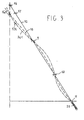
- the needle undergoes elastical reactions opposed by restraint reactions which rise to values much greater than the ones occurring when the needle is in normal position or when the axial shift occurs for only one restraint, and which, owing to the friction between needle and restraints, prevent its unthreading.
- the incidence angle of needle guiding group as to axis 8 is typically of 5°, but in Fig. 3 it is exaggerated to evidence the phenomenon.
- diaphragms 16,9, 10, 11 do not perform any action on the needle, which is free to fall down owing to its weight.
- the needle is therefore compelled to bend and get the position shown by hatched line 33.
- the needle bending is small, so the elastic reactions and the corresponding restraint reactions have small values.
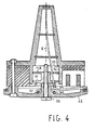
- the fundamental purpose of the invention is the one to reduce the distance between ruby 16 and basis plate 11 during the assembling phase assuring at the same time a controlled needle performance
- the bases plate can be mounted into the needle guiding group in order to be capable of an axial shift together with a contiguous diaphragm.
- Fig. 4 only shows the details of this solution useful to its understanding.
- plate 11 together with a contiguous diaphragm 11A, is housed (possibly with friction) into a cylindric or prismatic shaped housing 34 of bushing 7 in order to be able to take up different axial positions.
- Plates 11 and 11A can be pushed in a back position up to laying against a ledge 35 to allow the needle insertion and the head assembling.
- plate 11 When the assembling is completed plate 11 can be set again in working position by a screw 36 which, through armature retaining element 22, hold in a threaded housing of plates 11 and 11A.
- the invention can be applied not only to needle printing heads where needles and electromagnets are arranged on the same side as to the armatures, but also to printing heads where the electromagnets and the needles are arranged on opposite sides as to the attraction armatures, as for instance disclosed by US Patent No. 4,230,038.
- the slide of Fig. 2 can be provided with only one flexible tongue, instead of two, the relation teeth-grooves can be reversed (grooves into tongues and teeth on the sides of the needle guiding group) and other positioning elements such as screws or stop pins can be used to replace the couple teeth-grooves.
- the needle guiding friction that in the description is performed by a plurality of diaphragms, that is by elements of thin thickness can be performed by one or more continuous guiding elements extending along the needles of the kind disclosed for instance by US Patent No. 4,081,067 and by British Patent No. 1,450,346.
Landscapes
- Impact Printers (AREA)
Claims (6)
Applications Claiming Priority (2)
| Application Number | Priority Date | Filing Date | Title |
|---|---|---|---|
| IT2231584 | 1984-08-10 | ||
| IT22315/84A IT1175588B (it) | 1984-08-10 | 1984-08-10 | Testina stampante ad aghi perfezionata per un agevole assemblaggio |
Publications (3)
| Publication Number | Publication Date |
|---|---|
| EP0170976A2 EP0170976A2 (fr) | 1986-02-12 |
| EP0170976A3 EP0170976A3 (en) | 1986-08-06 |
| EP0170976B1 true EP0170976B1 (fr) | 1989-09-13 |
Family
ID=11194554
Family Applications (1)
| Application Number | Title | Priority Date | Filing Date |
|---|---|---|---|
| EP85109239A Expired EP0170976B1 (fr) | 1984-08-10 | 1985-07-23 | Tête d'impression à aiguilles à assemblage simple |
Country Status (3)
| Country | Link |
|---|---|
| EP (1) | EP0170976B1 (fr) |
| DE (1) | DE3572947D1 (fr) |
| IT (1) | IT1175588B (fr) |
Families Citing this family (3)
| Publication number | Priority date | Publication date | Assignee | Title |
|---|---|---|---|---|
| JPH0453949Y2 (fr) * | 1986-07-08 | 1992-12-18 | ||
| CN1029098C (zh) * | 1990-06-15 | 1995-06-28 | 精工爱普生株式会社 | 击点打印头及其制造方法 |
| DE4033698A1 (de) * | 1990-10-19 | 1992-04-30 | Mannesmann Ag | Verfahren zum drucken magnetisch lesbarer schriftzeichen und verwendung eines matrixdruckkopfes hierfuer sowie verfahren zu dessen herstellung |
Family Cites Families (3)
| Publication number | Priority date | Publication date | Assignee | Title |
|---|---|---|---|---|
| DE2702654A1 (de) * | 1974-06-25 | 1978-07-27 | Singer Co | Drahtmatrixdruckkopf |
| IT1099489B (it) * | 1978-09-11 | 1985-09-18 | Honeywell Inf Systems | Testina stampante a matrice perfezionata |
| DE3164230D1 (en) * | 1980-12-05 | 1984-07-19 | Tokyo Electric Co Ltd | Printing head of dot printer |
-
1984
- 1984-08-10 IT IT22315/84A patent/IT1175588B/it active
-
1985
- 1985-07-23 EP EP85109239A patent/EP0170976B1/fr not_active Expired
- 1985-07-23 DE DE8585109239T patent/DE3572947D1/de not_active Expired
Also Published As
| Publication number | Publication date |
|---|---|
| IT1175588B (it) | 1987-07-01 |
| EP0170976A3 (en) | 1986-08-06 |
| DE3572947D1 (en) | 1989-10-19 |
| IT8422315A0 (it) | 1984-08-10 |
| EP0170976A2 (fr) | 1986-02-12 |
Similar Documents
| Publication | Publication Date | Title |
|---|---|---|
| KR101989650B1 (ko) | 정렬핀을 클램프하기 위한 유연성 구조체를 갖는 광파이버 커넥터용 페룰 | |
| US5415559A (en) | Electrical connector having a plurality of contact pin springs | |
| EP1872954B1 (fr) | Tête d'impression à impact | |
| JPH0224983A (ja) | 電気コネクタ | |
| US6953285B2 (en) | Anti-backout latch for fiber optic connector | |
| DE69521106T2 (de) | Magnetkopfvorrichtung und magnetooptische Aufzeichnungsvorrichtung | |
| KR0121752B1 (ko) | 압전소자의 운동변환장치 및 그 제조방법 | |
| EP0170976B1 (fr) | Tête d'impression à aiguilles à assemblage simple | |
| US4660790A (en) | Cable support with tines | |
| EP0640855B1 (fr) | Appareil d'adjustage d'alignement des fibres optiques | |
| EP0374673B1 (fr) | Imprimante par points à aiguilles fonctionnant par percussion | |
| EP0413240B1 (fr) | Contact électrique | |
| EP2823966A1 (fr) | Dispositif pour alignement de tête | |
| EP0176974B1 (fr) | Rubis et agencement de guidage des aiguilles dans une tête d'impression à aiguilles | |
| KR920007468B1 (ko) | 비스루의 공급장치 | |
| EP0529345A2 (fr) | Assemblage de connecteur de bordure de carte | |
| US4511269A (en) | Cancel type printing head | |
| EP3659870B1 (fr) | Faisceau de câbles | |
| EP0053887A1 (fr) | Tête d'impression pour imprimante par points | |
| US4141661A (en) | Guide system for wire matrix printing | |
| EP0292297B1 (fr) | Machine à fabriquer des harnais de fil | |
| CA2252189C (fr) | Commutateur de fibres optiques n x 2n | |
| JPH0215390B2 (fr) | ||
| EP0175763B1 (fr) | Tete d'impression a aiguilles a haute vitesse munie d'un dispositif de decalage de la position d'impression des aiguilles | |
| JPH03193359A (ja) | ドツトマトリツクス印字ヘツド |
Legal Events
| Date | Code | Title | Description |
|---|---|---|---|
| PUAI | Public reference made under article 153(3) epc to a published international application that has entered the european phase |
Free format text: ORIGINAL CODE: 0009012 |
|
| AK | Designated contracting states |
Designated state(s): DE FR GB |
|
| PUAL | Search report despatched |
Free format text: ORIGINAL CODE: 0009013 |
|
| RHK1 | Main classification (correction) |
Ipc: B41J 7/48 |
|
| AK | Designated contracting states |
Kind code of ref document: A3 Designated state(s): DE FR GB |
|
| 17P | Request for examination filed |
Effective date: 19861124 |
|
| RAP1 | Party data changed (applicant data changed or rights of an application transferred) |
Owner name: HONEYWELL BULL ITALIA S.P.A. |
|
| 17Q | First examination report despatched |
Effective date: 19880531 |
|
| RAP1 | Party data changed (applicant data changed or rights of an application transferred) |
Owner name: BULL HN INFORMATION SYSTEMS ITALIA S.P.A. |
|
| GRAA | (expected) grant |
Free format text: ORIGINAL CODE: 0009210 |
|
| AK | Designated contracting states |
Kind code of ref document: B1 Designated state(s): DE FR GB |
|
| REF | Corresponds to: |
Ref document number: 3572947 Country of ref document: DE Date of ref document: 19891019 |
|
| ET | Fr: translation filed | ||
| PLBE | No opposition filed within time limit |
Free format text: ORIGINAL CODE: 0009261 |
|
| STAA | Information on the status of an ep patent application or granted ep patent |
Free format text: STATUS: NO OPPOSITION FILED WITHIN TIME LIMIT |
|
| 26N | No opposition filed | ||
| PGFP | Annual fee paid to national office [announced via postgrant information from national office to epo] |
Ref country code: GB Payment date: 19970714 Year of fee payment: 13 |
|
| PGFP | Annual fee paid to national office [announced via postgrant information from national office to epo] |
Ref country code: FR Payment date: 19970718 Year of fee payment: 13 |
|
| PGFP | Annual fee paid to national office [announced via postgrant information from national office to epo] |
Ref country code: DE Payment date: 19970801 Year of fee payment: 13 |
|
| PG25 | Lapsed in a contracting state [announced via postgrant information from national office to epo] |
Ref country code: GB Free format text: LAPSE BECAUSE OF NON-PAYMENT OF DUE FEES Effective date: 19980723 |
|
| GBPC | Gb: european patent ceased through non-payment of renewal fee |
Effective date: 19980723 |
|
| PG25 | Lapsed in a contracting state [announced via postgrant information from national office to epo] |
Ref country code: FR Free format text: LAPSE BECAUSE OF NON-PAYMENT OF DUE FEES Effective date: 19990331 |
|
| PG25 | Lapsed in a contracting state [announced via postgrant information from national office to epo] |
Ref country code: DE Free format text: LAPSE BECAUSE OF NON-PAYMENT OF DUE FEES Effective date: 19990501 |
|
| REG | Reference to a national code |
Ref country code: FR Ref legal event code: ST |