EP0171058A2 - Verfahren zum Berechnen des Spannungszustandes einer Schraube - Google Patents
Verfahren zum Berechnen des Spannungszustandes einer Schraube Download PDFInfo
- Publication number
- EP0171058A2 EP0171058A2 EP85109864A EP85109864A EP0171058A2 EP 0171058 A2 EP0171058 A2 EP 0171058A2 EP 85109864 A EP85109864 A EP 85109864A EP 85109864 A EP85109864 A EP 85109864A EP 0171058 A2 EP0171058 A2 EP 0171058A2
- Authority
- EP
- European Patent Office
- Prior art keywords
- tightening
- turning angle
- torque
- screw member
- plastic
- Prior art date
- Legal status (The legal status is an assumption and is not a legal conclusion. Google has not performed a legal analysis and makes no representation as to the accuracy of the status listed.)
- Granted
Links
Images

Classifications
-
- B—PERFORMING OPERATIONS; TRANSPORTING
- B25—HAND TOOLS; PORTABLE POWER-DRIVEN TOOLS; MANIPULATORS
- B25B—TOOLS OR BENCH DEVICES NOT OTHERWISE PROVIDED FOR, FOR FASTENING, CONNECTING, DISENGAGING, OR HOLDING
- B25B23/00—Details of, or accessories for, spanners, wrenches, screwdrivers
- B25B23/14—Arrangement of torque limiters or torque indicators in wrenches or screwdrivers
-
- B—PERFORMING OPERATIONS; TRANSPORTING
- B23—MACHINE TOOLS; METAL-WORKING NOT OTHERWISE PROVIDED FOR
- B23P—METAL-WORKING NOT OTHERWISE PROVIDED FOR; COMBINED OPERATIONS; UNIVERSAL MACHINE TOOLS
- B23P19/00—Machines for simply fitting together or separating metal parts or objects, or metal and non-metal parts, whether or not involving some deformation; Tools or devices therefor so far as not provided for in other classes
- B23P19/04—Machines for simply fitting together or separating metal parts or objects, or metal and non-metal parts, whether or not involving some deformation; Tools or devices therefor so far as not provided for in other classes for assembling or disassembling parts
- B23P19/06—Screw or nut setting or loosening machines
- B23P19/065—Arrangements for torque limiters or torque indicators in screw or nut setting machines
- B23P19/066—Arrangements for torque limiters or torque indicators in screw or nut setting machines by electrical means
-
- G—PHYSICS
- G05—CONTROLLING; REGULATING
- G05D—SYSTEMS FOR CONTROLLING OR REGULATING NON-ELECTRIC VARIABLES
- G05D17/00—Control of torque; Control of mechanical power
- G05D17/02—Control of torque; Control of mechanical power characterised by the use of electric means
-
- Y—GENERAL TAGGING OF NEW TECHNOLOGICAL DEVELOPMENTS; GENERAL TAGGING OF CROSS-SECTIONAL TECHNOLOGIES SPANNING OVER SEVERAL SECTIONS OF THE IPC; TECHNICAL SUBJECTS COVERED BY FORMER USPC CROSS-REFERENCE ART COLLECTIONS [XRACs] AND DIGESTS
- Y10—TECHNICAL SUBJECTS COVERED BY FORMER USPC
- Y10T—TECHNICAL SUBJECTS COVERED BY FORMER US CLASSIFICATION
- Y10T29/00—Metal working
- Y10T29/49—Method of mechanical manufacture
- Y10T29/49764—Method of mechanical manufacture with testing or indicating
- Y10T29/49766—Method of mechanical manufacture with testing or indicating torquing threaded assemblage or determining torque herein
- Y10T29/49767—Determining relative number of threaded member rotations
-
- Y—GENERAL TAGGING OF NEW TECHNOLOGICAL DEVELOPMENTS; GENERAL TAGGING OF CROSS-SECTIONAL TECHNOLOGIES SPANNING OVER SEVERAL SECTIONS OF THE IPC; TECHNICAL SUBJECTS COVERED BY FORMER USPC CROSS-REFERENCE ART COLLECTIONS [XRACs] AND DIGESTS
- Y10—TECHNICAL SUBJECTS COVERED BY FORMER USPC
- Y10T—TECHNICAL SUBJECTS COVERED BY FORMER US CLASSIFICATION
- Y10T29/00—Metal working
- Y10T29/53—Means to assemble or disassemble
- Y10T29/53687—Means to assemble or disassemble by rotation of work part
Definitions
- This invention relates to a method of evaluating the tightening condition of a screw member tightened in plastic tightening by a nut runner.
- a cylinder head is clamped to a cylinder block by tightening ten or so clamp bolts by a nut runner.
- the tightening condition of the clamp bolts must be strictly controlled.
- This manner of tightening a screw member is generally referred to as "plastic tightening".
- plastic tightening In the plastic tightening, when the force imparted to the screw member before terminating tightening enters far into the plastic range, the fatigue strength of the screw member is lowered and accordingly the tightening condition must be more strictly controlled.
- the plastic tightening condition is controlled by a "torque gradient method" in which the instantaneous gradient of a torque-revolution curve while a screw member is tightened, and also whether or not the state of change in the instantaneous gradient signal representing the instantaneous gradient comes to indicate a special point such as a yield point, i.e., whether or not change in the torque increasing rate (ratio of increase in torque to increase in the tightening turning angle) is reduced below a predetermined value, is detected, and the time the tightening of the screw member is to be terminated is determined on the basis of the detection.
- a yield point i.e., whether or not change in the torque increasing rate (ratio of increase in torque to increase in the tightening turning angle) is reduced below a predetermined value
- the torque increasing rate changes in the elastic range depending on the manufacturing accuracy of the screw member, physical properties of the member to be clamped' by the screw member and the like, and accordingly if the change in the elastic range is similar to that indicating the yield point, the change can be mistaken for the change indicating the yield point to terminate tightening of the screw member before it is sufficiently tightened up.
- the primary object of the present invention is to provide a method of precisely evaluating the plastic tightening condition of a screw member, thereby facilitating optimal control of the plastic tightening.
- the turning angle of the screw member and the tightening torque of the same are detected.
- the ratio of increase in torque to increase in the tightening turning angle, that is, the torque increasing rate is calculated. Tightening of the screw member is terminated when the force imparted to the screw member exceeds the elastic limit of the screw member and reaches a predetermined tightening point in the plastic range. The total tightening turning angle and the final tightening torque are detected upon termination of the tightening.
- the elastic tightening turning angle portion of the total tightening turning angle is calculated on the basis of the final tightening torque and the torque increasing rate in the elastic range, and the plastic tightening turning angle portion of the total tightening turning angle is calculated by subtracting the elastic tightening turning angle portion from the total tightening turning angle.
- the plastic tightening turning angle portion thus obtained is compared with a preset tolerance range to evaluate the tightening.
- the ratio of increase in torque T2-Tl (Figure 1) when the tightening torque T increases from Tl to T2 to increase in the turning angle 8 in the elastic range in which the turning angle and the tightening angle linearly change is calculated. That is, the torque increasing rate dT/d0 representing the inclination a of turning angle-tightening angle curve is calculated.
- the tightening torque T3 and the turning angle 6 upon termination of tightening are detected.
- Elastic tightening turning angle 61 when the tightening torque T3 upon termination of tightening is assumed to be the elastic limit torque, is calculated on the basis of the torque increasing rate dT/d6 (inclination or angle a).
- the difference 82 between the detected turning angle 63 upon termination of tightening and the elastic tightening angle 61 represents the turning angle in the plastic range (the amount of plastic elongation of the screw member).
- the plastic tightening turning angle 62 is compared with a preset value. When the plastic tightening angle 62 for a given screw member is larger than the preset value, it is determined that the amount of plastic elongation of the screw member is larger than the tolerance and the screw member is insufficient in load bearing ability. On the other hand, when the plastic tightening turning angle 62 is smaller than the preset value, it is determined that the screw member has not been subjected to plastic tightening yet.
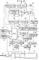
- a nut runner 1 is provided with a socket 3 adapted to be engaged with a screw member 2 such as a bolt or a nut.
- the driving force of a motor 4 is transmitted to the socket 3 by way of reduction gears 5.
- the nut runner 1 is further provided with a turning angle detector 6 for detecting the tightening turning angle 6 and a torque detector 7 for detecting the tightening torque.
- the detecting signals of the turning angle detector 6 and the torque detector 7 are delivered to an evaluating circuit 8 for evaluating tightening condition of the screw member 2.
- the ratio of increase in torque T2-T1 when the tightening torque T increases from Tl to T2 to increase in turning angle 6 in the elastic range, that is, the torque increasing rate dT/d ⁇ is stored.
- the tightening torque T3 and the turning angle 6 upon termination of tightening are detected.
- Elastic tightening turning angle 61 is calculated on the basis of the torque increasing rate dT/d6.
- the plastic tightening turning angle 62 is compared with a preset value having a predetermined width. That is, it is determined whether or not the plastic tightening angle 62 is within a preset range.
- a preset value having a predetermined width. That is, it is determined whether or not the plastic tightening angle 62 is within a preset range.
- the plastic tightening angle 82 for a given screw member is above the preset value, it is determined that the amount of plastic elongation of the screw member is larger than the tolerance and the screw member is insufficient in load bearing ability.
- the plastic tightening turning angle 62 is below the preset value, it is determined that the screw member has not yet been subjected to plastic tightening.
- the output signal of the torque detector 7 for detecting the tightening torque of the nut runner 1 is input into first and second comparators 15 and 16 and compared with preset torque values Tl and T2 respectively generated from preset torque value generators 13 and 14.
- the outputs of the first and second comparators 15 and 16 are input into a logic circuit 17 which opens and closes first and second gate circuits 28 and 31 according to the outputs of the comparators 15 and 16.
- the first gate circuit 28 controls initiation and termination of count of pulse signals from the turning angle detector in a first counter 29 and the second gate circuit 31 controls initiation and termination of count of pulse signals from the turning angle detector in a second counter 32.
- the preset torque values Tl and T2 generated from the preset torque value generators 13 and 14 have been experimentally determined in advance according to the screw member 2 to be used.
- the logic circuit 17 closes an analogue switch 18 according to the output of the first comparator 15 to permit transmission of the output signal of the torque detector 7 to a peak hold circuit (memory circuit) 19 which stores a peak value of changing tightening torque T.
- a peak hold circuit memory circuit
- the peak value of the tightening torque T stored in the peak hold circuit 19 increases with progress of tightening.
- an analogue switch 27 is kept open by the logic circuit 17, and the output of the peak hold circuit 19 (D.C.) is delivered to a voltage follower 21 by way of a resistor 21.
- D.C. the output of the peak hold circuit 19
- the difference El-Eo represents the torque increasing rate.
- the output El has a voltage proportional to the present peak value and the output Eo has a voltage proportional to the peak value at a time earlier by a delay time determined by the value R2 of the resistor 22 and the capacity Cl of the capacitor 23. Therefore, the value R2 of the resistor 22 and the capacity Cl of the capacitor 23 are selected according to the torque increasing rate corresponding to the screw member 2 to be used.
- the subtracting circuit 24 calculates the voltage difference El-Eo.
- the output of the subtracting circuit 24 is delivered to a holding circuit 26 by way of an analogue switch 25 which is closed under the control of a signal from the logic circuit 17, and stored in the holding circuit 26.
- a tightening termination turning angle 6 0 defining the point at which tightening of the screw member 2 by the nut runner 1 is to be terminated is set by a preset value generator 33 and the preset tightening termination turning angle ⁇ o generated by the preset value generator 33 is input into a comparator 34.
- Into the comparator 34 is also input a detecting signal from the second counter 32 representing the total tightening turning angle 63, and when the total tightening turning angle 63 becomes equal to the preset tightening termination turning angle 6 0 , an output of the comparator 34 is delivered to the logic circuit 17.
- the output of the subtracting circuit 35 is compared, by a comparator 37, with a preset value (tolerance) generated from a preset value generator 36 for setting a preset value of the plastic tightening turning angle 82.
- the tightening condition of the screw member 2 is evaluated on the basis of the output of the comparator 37.
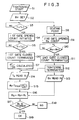
- step Sl the motor 4 of the nut runner 1 is energized to start tightening of the screw member 2.
- step S2 the preset tightening termination turning angle 6 0 is read in.
- step S8 a seating point at which the screw member is seated and from which the turning torque begins to increase or tightening of the screw member is initiated is calculated.
- step S9 the second gate 31 is opened and the total tightening turning angle 63 is detected by the second counter 32. Then in step S10, it is determined whether or not the detected total tightening turning angle 63 is equal to the preset tightening termination angle 8 0 .
- step S12 When the detected total tightening turning angle ⁇ 3 becomes equal to the preset tightening termination angle ⁇ o, the second gate 31 is closed (step Sll). Thereafter, the motor 4 of the nut runner 1 is de-energized to terminate tightening (step S12).
- step S3 it is determined whether or not the torque value T detected by the torque detector 7 is equal to the preset torque value Tl in step S3.
- the first gate 28 is opened to initiate counting of the tightening turning angle by the first counter 29 (step S4).
- step S5 it is determined whether or not the detected torque T is equal to the preset torque value T2.
- the first gate 28 is closed to terminate counting of the tightening turning angle by the first counter 29 (step S6).
- step S7 the torque increasing rate dT/d ⁇ is calculated.
- the total tightening turning angle 83 is read in step S13, and the final tightening torque T3 is read in step S14.
- the calculated value of the plastic tightening angle 82 is compared with the preset value in step S17 and when it is outside the tolerance range, it is determined that the tightening is not satisfactory (step S18) and otherwise it is determined that the tightening is satisfactory (step S19).
Landscapes
- Engineering & Computer Science (AREA)
- Mechanical Engineering (AREA)
- Physics & Mathematics (AREA)
- General Physics & Mathematics (AREA)
- Automation & Control Theory (AREA)
- Details Of Spanners, Wrenches, And Screw Drivers And Accessories (AREA)
Applications Claiming Priority (2)
| Application Number | Priority Date | Filing Date | Title |
|---|---|---|---|
| JP165149/84 | 1984-08-07 | ||
| JP59165149A JPS6144582A (ja) | 1984-08-07 | 1984-08-07 | ナツトランナ−における塑性締め良否判定方法 |
Publications (3)
| Publication Number | Publication Date |
|---|---|
| EP0171058A2 true EP0171058A2 (de) | 1986-02-12 |
| EP0171058A3 EP0171058A3 (en) | 1987-11-11 |
| EP0171058B1 EP0171058B1 (de) | 1990-05-02 |
Family
ID=15806809
Family Applications (1)
| Application Number | Title | Priority Date | Filing Date |
|---|---|---|---|
| EP85109864A Expired - Lifetime EP0171058B1 (de) | 1984-08-07 | 1985-08-06 | Verfahren zum Berechnen des Spannungszustandes einer Schraube |
Country Status (4)
| Country | Link |
|---|---|
| US (1) | US4620450A (de) |
| EP (1) | EP0171058B1 (de) |
| JP (1) | JPS6144582A (de) |
| DE (1) | DE3577412D1 (de) |
Cited By (7)
| Publication number | Priority date | Publication date | Assignee | Title |
|---|---|---|---|---|
| FR2625338A1 (fr) * | 1987-12-24 | 1989-06-30 | Szerszamgepipari Muevek | Procede pour developper une force de serrage par programmation numerique et son dispositif de mise en oeuvre, en particulier pour la poupee mobile de machines-outils |
| US5229931A (en) * | 1988-09-21 | 1993-07-20 | Honda Giken Kogyo Kabushiki Kaisha | Nut runner control system and method of monitoring nut runners |
| GB2225130B (en) * | 1988-09-21 | 1993-08-04 | Honda Motor Co Ltd | Method of monitoring nut runners |
| EP0642890A1 (de) * | 1993-09-09 | 1995-03-15 | Robert Bosch Gmbh | Verfahren zum Herstellen einer Fügeverbindung, insbesondere einer Schraubverbindung |
| EP2042262A1 (de) * | 2007-09-25 | 2009-04-01 | Mazda Motor Corporation | Bolzenschließverfahren, Computerprogrammprodukt und Vorrichtung |
| EP2340424A4 (de) * | 2008-10-22 | 2015-03-04 | Atlas Copco Ind Tech Ab | Testverfahren und werkzeug zum testen befestigter befestigungen |
| EP2826596A3 (de) * | 2013-07-19 | 2015-07-22 | Panasonic Intellectual Property Management Co., Ltd. | Schlagdrehwerkzeug und Schlagdrehwerkzeugaufsatz |
Families Citing this family (27)
| Publication number | Priority date | Publication date | Assignee | Title |
|---|---|---|---|---|
| FR2589096B1 (fr) * | 1985-10-29 | 1990-10-19 | Framatome Sa | Procede et dispositif de recheche de la position optima de vissage de goujons de grandes dimensions |
| US4941362A (en) * | 1987-06-29 | 1990-07-17 | Sps Technologies, Inc. | Torque and angular displacement sensing in controlled wrenches |
| US4823616A (en) * | 1987-06-29 | 1989-04-25 | Sps Technologies, Inc. | Torque and angular displacement sensing in yield threshold controlled wrenches |
| JPH07106548B2 (ja) * | 1988-01-14 | 1995-11-15 | 林時計工業株式会社 | 滑り検出機能を備えた電動ドライバ |
| US4995145A (en) * | 1990-01-08 | 1991-02-26 | Allen-Bradley Company, Inc. | Reduction of relaxation induced tension scatter in fasteners |
| US5212862A (en) * | 1990-10-09 | 1993-05-25 | Allen-Bradley Company, Inc. | Torque-angle window control for threaded fasteners |
| US5131130A (en) * | 1990-10-09 | 1992-07-21 | Allen-Bradley Company, Inc. | Torque-angle window control for threaded fasteners |
| US5321506A (en) * | 1991-06-14 | 1994-06-14 | Usx Corporation | Automatic screw-on pipe couplings |
| US5315501A (en) * | 1992-04-03 | 1994-05-24 | The Stanley Works | Power tool compensator for torque overshoot |
| US5366026A (en) * | 1992-08-28 | 1994-11-22 | Nissan Motor Company, Ltd. | Impact type clamping apparatus |
| US5396703A (en) * | 1993-04-20 | 1995-03-14 | Ingersoll-Rand Company | Method of inspecting bearing insert assemblies |
| US5727299A (en) * | 1996-06-24 | 1998-03-17 | Dominion Tool & Die Company, Inc. | Wheel alignment machine and method |
| FR2771040B1 (fr) * | 1997-11-17 | 2000-01-07 | Serac Group | Procede de commande d'une broche de vissage |
| SE513563C2 (sv) * | 1998-03-19 | 2000-10-02 | Atlas Copco Tools Ab | Metod för självprogrammering av styrsystem för kraftmutterdragare under initiala åtdragningsförlopp |
| US6314817B1 (en) | 1998-05-14 | 2001-11-13 | Atlas Copco Tools Ab | Method for tightening a threaded fastener above its yield point |
| SE518436C2 (sv) * | 1998-05-14 | 2002-10-08 | Atlas Copco Tools Ab | Metod för bestämning av axialkraften i ett gängat fästelement vid åtdragning över sträckgränsen |
| KR100496658B1 (ko) * | 2003-03-31 | 2005-06-22 | 주식회사 세한전동 | 조립 검증 기능의 카운터를 구비한 전동 드라이버 시스템 |
| DE102007019409B3 (de) * | 2007-04-23 | 2008-11-13 | Lösomat Schraubtechnik Neef Gmbh | Kraftschrauber |
| JP5645423B2 (ja) * | 2010-02-23 | 2014-12-24 | キヤノン株式会社 | 回転駆動装置及びロボットアーム |
| KR200490007Y1 (ko) | 2015-04-28 | 2019-11-04 | 밀워키 일렉트릭 툴 코포레이션 | 정밀 토크 스크류드라이버 |
| US10357871B2 (en) | 2015-04-28 | 2019-07-23 | Milwaukee Electric Tool Corporation | Precision torque screwdriver |
| JP6973352B2 (ja) * | 2018-10-29 | 2021-11-24 | オムロン株式会社 | 底付き判定基準設定方法 |
| JP7443931B2 (ja) * | 2020-05-27 | 2024-03-06 | コニカミノルタ株式会社 | ネジ締め装置、およびネジ締め方法 |
| JP7592844B2 (ja) | 2020-08-10 | 2024-12-02 | ミルウォーキー エレクトリック ツール コーポレイション | クラッチ設定センサを備える電動ドライバ |
| CN116669908B (zh) * | 2020-12-22 | 2025-12-30 | 发那科株式会社 | 螺纹紧固系统 |
| CN116160232B (zh) * | 2022-12-16 | 2025-10-24 | 国能铁路装备有限责任公司 | 机车车轮部件组装方法 |
| CN117161739A (zh) * | 2023-08-30 | 2023-12-05 | 浙江吉利控股集团有限公司 | 气缸盖螺栓拧紧方法及装置 |
Family Cites Families (8)
| Publication number | Priority date | Publication date | Assignee | Title |
|---|---|---|---|---|
| USRE31569E (en) * | 1976-08-09 | 1984-05-01 | Rockwell International Corporation | Tension control of fasteners |
| ZA774188B (en) * | 1976-08-09 | 1979-05-30 | Rockwell International Corp | Tension control of fasteners |
| US4179786A (en) * | 1976-08-09 | 1979-12-25 | Rockwell International Corporation | Tension control of fasteners |
| SE423344B (sv) * | 1976-11-22 | 1982-05-03 | Atlas Copco Ab | Forfarande och anordning for reglerad atdragning av skruvforband |
| US4106176A (en) * | 1977-04-06 | 1978-08-15 | Ingersoll-Rand Company | Method and apparatus for fastener tensioning |
| US4344216A (en) * | 1979-12-10 | 1982-08-17 | Sps Technologies, Inc. | Apparatus and method for tightening an assembly |
| GB2096361A (en) * | 1981-03-31 | 1982-10-13 | Int Harvester Co | Method and apparatus for automatically tensioning threaded fasteners |
| US4510424A (en) * | 1983-09-08 | 1985-04-09 | Daiichi Dentsu Kabushiki Kaisha | Nut runner control circuit |
-
1984
- 1984-08-07 JP JP59165149A patent/JPS6144582A/ja active Granted
-
1985
- 1985-08-05 US US06/762,337 patent/US4620450A/en not_active Expired - Lifetime
- 1985-08-06 DE DE8585109864T patent/DE3577412D1/de not_active Expired - Fee Related
- 1985-08-06 EP EP85109864A patent/EP0171058B1/de not_active Expired - Lifetime
Cited By (9)
| Publication number | Priority date | Publication date | Assignee | Title |
|---|---|---|---|---|
| FR2625338A1 (fr) * | 1987-12-24 | 1989-06-30 | Szerszamgepipari Muevek | Procede pour developper une force de serrage par programmation numerique et son dispositif de mise en oeuvre, en particulier pour la poupee mobile de machines-outils |
| US5229931A (en) * | 1988-09-21 | 1993-07-20 | Honda Giken Kogyo Kabushiki Kaisha | Nut runner control system and method of monitoring nut runners |
| GB2225130B (en) * | 1988-09-21 | 1993-08-04 | Honda Motor Co Ltd | Method of monitoring nut runners |
| EP0642890A1 (de) * | 1993-09-09 | 1995-03-15 | Robert Bosch Gmbh | Verfahren zum Herstellen einer Fügeverbindung, insbesondere einer Schraubverbindung |
| US5631823A (en) * | 1993-09-09 | 1997-05-20 | Robert Bosch Gmbh | Method of making a connection, particulary a screw connection |
| EP2042262A1 (de) * | 2007-09-25 | 2009-04-01 | Mazda Motor Corporation | Bolzenschließverfahren, Computerprogrammprodukt und Vorrichtung |
| EP2340424A4 (de) * | 2008-10-22 | 2015-03-04 | Atlas Copco Ind Tech Ab | Testverfahren und werkzeug zum testen befestigter befestigungen |
| EP2826596A3 (de) * | 2013-07-19 | 2015-07-22 | Panasonic Intellectual Property Management Co., Ltd. | Schlagdrehwerkzeug und Schlagdrehwerkzeugaufsatz |
| US9701000B2 (en) | 2013-07-19 | 2017-07-11 | Panasonic Intellectual Property Management Co., Ltd. | Impact rotation tool and impact rotation tool attachment |
Also Published As
| Publication number | Publication date |
|---|---|
| EP0171058A3 (en) | 1987-11-11 |
| JPH0549434B2 (de) | 1993-07-26 |
| US4620450A (en) | 1986-11-04 |
| EP0171058B1 (de) | 1990-05-02 |
| DE3577412D1 (de) | 1990-06-07 |
| JPS6144582A (ja) | 1986-03-04 |
Similar Documents
| Publication | Publication Date | Title |
|---|---|---|
| US4620450A (en) | Method of evaluating tightening condition of screw | |
| US4685050A (en) | Method of tightening threaded fasteners | |
| US6167606B1 (en) | Method for tightening a screw connection by means of an impact screwdriver having a variable speed electric drive motor | |
| GB1594479A (en) | Tightening system | |
| US4828473A (en) | Injection control apparatus for an injection-molding machine | |
| US5631823A (en) | Method of making a connection, particulary a screw connection | |
| KR100203571B1 (ko) | 최적시간 볼트체결방법 | |
| US4562389A (en) | Automatic screwdriver or torquing tool control system | |
| US4571696A (en) | Electronically controlled screwdriver with quality check indicator | |
| SE440868B (sv) | Forfarande och anordning for reglerad atdragning av festelement | |
| US4413396A (en) | Microprocessor control yield point tightening system | |
| US4510424A (en) | Nut runner control circuit | |
| GB2096361A (en) | Method and apparatus for automatically tensioning threaded fasteners | |
| US5152046A (en) | Fastener tightening method | |
| US4485786A (en) | Air-fuel ratio control apparatus | |
| JPS59348B2 (ja) | ボルト締付方法 | |
| JP2864754B2 (ja) | チャック制御装置 | |
| US4458190A (en) | Electric discharge machining control device | |
| JP2586943B2 (ja) | 射出成形機の製品良否判別装置 | |
| JPS61103784A (ja) | ねじ部材の捻込み制御装置 | |
| JP2770107B2 (ja) | ボルト・ナット異常締め付け検出方法 | |
| US4078273A (en) | Process for the preuse work-hardening of bolts | |
| JP2658487B2 (ja) | ねじ締付方法 | |
| GB2148551A (en) | Apparatus for tightening a threaded fastener | |
| JPS61284376A (ja) | 耐力検出ボルト締付機 |
Legal Events
| Date | Code | Title | Description |
|---|---|---|---|
| PUAI | Public reference made under article 153(3) epc to a published international application that has entered the european phase |
Free format text: ORIGINAL CODE: 0009012 |
|
| 17P | Request for examination filed |
Effective date: 19850913 |
|
| AK | Designated contracting states |
Designated state(s): DE FR GB |
|
| PUAL | Search report despatched |
Free format text: ORIGINAL CODE: 0009013 |
|
| AK | Designated contracting states |
Kind code of ref document: A3 Designated state(s): DE FR GB |
|
| 17Q | First examination report despatched |
Effective date: 19880823 |
|
| GRAA | (expected) grant |
Free format text: ORIGINAL CODE: 0009210 |
|
| AK | Designated contracting states |
Kind code of ref document: B1 Designated state(s): DE FR GB |
|
| REF | Corresponds to: |
Ref document number: 3577412 Country of ref document: DE Date of ref document: 19900607 |
|
| ET | Fr: translation filed | ||
| ET1 | Fr: translation filed ** revision of the translation of the patent or the claims | ||
| PLBE | No opposition filed within time limit |
Free format text: ORIGINAL CODE: 0009261 |
|
| STAA | Information on the status of an ep patent application or granted ep patent |
Free format text: STATUS: NO OPPOSITION FILED WITHIN TIME LIMIT |
|
| 26N | No opposition filed | ||
| PGFP | Annual fee paid to national office [announced via postgrant information from national office to epo] |
Ref country code: GB Payment date: 19960729 Year of fee payment: 12 |
|
| PGFP | Annual fee paid to national office [announced via postgrant information from national office to epo] |
Ref country code: FR Payment date: 19960809 Year of fee payment: 12 |
|
| PGFP | Annual fee paid to national office [announced via postgrant information from national office to epo] |
Ref country code: DE Payment date: 19960812 Year of fee payment: 12 |
|
| PG25 | Lapsed in a contracting state [announced via postgrant information from national office to epo] |
Ref country code: GB Free format text: LAPSE BECAUSE OF NON-PAYMENT OF DUE FEES Effective date: 19970806 |
|
| GBPC | Gb: european patent ceased through non-payment of renewal fee |
Effective date: 19970806 |
|
| PG25 | Lapsed in a contracting state [announced via postgrant information from national office to epo] |
Ref country code: FR Free format text: LAPSE BECAUSE OF NON-PAYMENT OF DUE FEES Effective date: 19980430 |
|
| PG25 | Lapsed in a contracting state [announced via postgrant information from national office to epo] |
Ref country code: DE Free format text: LAPSE BECAUSE OF NON-PAYMENT OF DUE FEES Effective date: 19980501 |
|
| REG | Reference to a national code |
Ref country code: FR Ref legal event code: ST |