EP0171126A1 - Dispositif de remplissage - Google Patents
Dispositif de remplissage Download PDFInfo
- Publication number
- EP0171126A1 EP0171126A1 EP85201280A EP85201280A EP0171126A1 EP 0171126 A1 EP0171126 A1 EP 0171126A1 EP 85201280 A EP85201280 A EP 85201280A EP 85201280 A EP85201280 A EP 85201280A EP 0171126 A1 EP0171126 A1 EP 0171126A1
- Authority
- EP
- European Patent Office
- Prior art keywords
- closure
- filling
- external thread
- cylindrical part
- gas container
- Prior art date
- Legal status (The legal status is an assumption and is not a legal conclusion. Google has not performed a legal analysis and makes no representation as to the accuracy of the status listed.)
- Granted
Links
- 238000007789 sealing Methods 0.000 claims abstract description 10
- 239000007789 gas Substances 0.000 description 27
- IJGRMHOSHXDMSA-UHFFFAOYSA-N Atomic nitrogen Chemical compound N#N IJGRMHOSHXDMSA-UHFFFAOYSA-N 0.000 description 10
- 229910052757 nitrogen Inorganic materials 0.000 description 5
- 230000007423 decrease Effects 0.000 description 3
- 239000002184 metal Substances 0.000 description 2
- 239000000725 suspension Substances 0.000 description 2
- 230000007797 corrosion Effects 0.000 description 1
- 238000005260 corrosion Methods 0.000 description 1
- 238000009434 installation Methods 0.000 description 1
- 230000003993 interaction Effects 0.000 description 1
- 238000003754 machining Methods 0.000 description 1
- 238000004519 manufacturing process Methods 0.000 description 1
- 239000012528 membrane Substances 0.000 description 1
- 238000000034 method Methods 0.000 description 1
- 125000004433 nitrogen atom Chemical group N* 0.000 description 1
- 238000003825 pressing Methods 0.000 description 1
Images

Classifications
-
- F—MECHANICAL ENGINEERING; LIGHTING; HEATING; WEAPONS; BLASTING
- F15—FLUID-PRESSURE ACTUATORS; HYDRAULICS OR PNEUMATICS IN GENERAL
- F15B—SYSTEMS ACTING BY MEANS OF FLUIDS IN GENERAL; FLUID-PRESSURE ACTUATORS, e.g. SERVOMOTORS; DETAILS OF FLUID-PRESSURE SYSTEMS, NOT OTHERWISE PROVIDED FOR
- F15B1/00—Installations or systems with accumulators; Supply reservoir or sump assemblies
- F15B1/02—Installations or systems with accumulators
- F15B1/04—Accumulators
- F15B1/08—Accumulators using a gas cushion; Gas charging devices; Indicators or floats therefor
-
- F—MECHANICAL ENGINEERING; LIGHTING; HEATING; WEAPONS; BLASTING
- F16—ENGINEERING ELEMENTS AND UNITS; GENERAL MEASURES FOR PRODUCING AND MAINTAINING EFFECTIVE FUNCTIONING OF MACHINES OR INSTALLATIONS; THERMAL INSULATION IN GENERAL
- F16F—SPRINGS; SHOCK-ABSORBERS; MEANS FOR DAMPING VIBRATION
- F16F9/00—Springs, vibration-dampers, shock-absorbers, or similarly-constructed movement-dampers using a fluid or the equivalent as damping medium
- F16F9/32—Details
- F16F9/43—Filling or drainage arrangements, e.g. for supply of gas
-
- F—MECHANICAL ENGINEERING; LIGHTING; HEATING; WEAPONS; BLASTING
- F17—STORING OR DISTRIBUTING GASES OR LIQUIDS
- F17C—VESSELS FOR CONTAINING OR STORING COMPRESSED, LIQUEFIED OR SOLIDIFIED GASES; FIXED-CAPACITY GAS-HOLDERS; FILLING VESSELS WITH, OR DISCHARGING FROM VESSELS, COMPRESSED, LIQUEFIED, OR SOLIDIFIED GASES
- F17C5/00—Methods or apparatus for filling containers with liquefied, solidified, or compressed gases under pressures
- F17C5/06—Methods or apparatus for filling containers with liquefied, solidified, or compressed gases under pressures for filling with compressed gases
-
- B—PERFORMING OPERATIONS; TRANSPORTING
- B60—VEHICLES IN GENERAL
- B60G—VEHICLE SUSPENSION ARRANGEMENTS
- B60G2206/00—Indexing codes related to the manufacturing of suspensions: constructional features, the materials used, procedures or tools
- B60G2206/01—Constructional features of suspension elements, e.g. arms, dampers, springs
- B60G2206/40—Constructional features of dampers and/or springs
- B60G2206/42—Springs
- B60G2206/422—Accumulators for hydropneumatic springs
- B60G2206/4222—Accumulators for hydropneumatic springs with a flexible separating wall; Membrane construction
-
- F—MECHANICAL ENGINEERING; LIGHTING; HEATING; WEAPONS; BLASTING
- F15—FLUID-PRESSURE ACTUATORS; HYDRAULICS OR PNEUMATICS IN GENERAL
- F15B—SYSTEMS ACTING BY MEANS OF FLUIDS IN GENERAL; FLUID-PRESSURE ACTUATORS, e.g. SERVOMOTORS; DETAILS OF FLUID-PRESSURE SYSTEMS, NOT OTHERWISE PROVIDED FOR
- F15B2201/00—Accumulators
- F15B2201/20—Accumulator cushioning means
- F15B2201/205—Accumulator cushioning means using gas
-
- F—MECHANICAL ENGINEERING; LIGHTING; HEATING; WEAPONS; BLASTING
- F15—FLUID-PRESSURE ACTUATORS; HYDRAULICS OR PNEUMATICS IN GENERAL
- F15B—SYSTEMS ACTING BY MEANS OF FLUIDS IN GENERAL; FLUID-PRESSURE ACTUATORS, e.g. SERVOMOTORS; DETAILS OF FLUID-PRESSURE SYSTEMS, NOT OTHERWISE PROVIDED FOR
- F15B2201/00—Accumulators
- F15B2201/30—Accumulator separating means
- F15B2201/315—Accumulator separating means having flexible separating means
- F15B2201/3151—Accumulator separating means having flexible separating means the flexible separating means being diaphragms or membranes
-
- F—MECHANICAL ENGINEERING; LIGHTING; HEATING; WEAPONS; BLASTING
- F15—FLUID-PRESSURE ACTUATORS; HYDRAULICS OR PNEUMATICS IN GENERAL
- F15B—SYSTEMS ACTING BY MEANS OF FLUIDS IN GENERAL; FLUID-PRESSURE ACTUATORS, e.g. SERVOMOTORS; DETAILS OF FLUID-PRESSURE SYSTEMS, NOT OTHERWISE PROVIDED FOR
- F15B2201/00—Accumulators
- F15B2201/40—Constructional details of accumulators not otherwise provided for
- F15B2201/415—Gas ports
-
- F—MECHANICAL ENGINEERING; LIGHTING; HEATING; WEAPONS; BLASTING
- F15—FLUID-PRESSURE ACTUATORS; HYDRAULICS OR PNEUMATICS IN GENERAL
- F15B—SYSTEMS ACTING BY MEANS OF FLUIDS IN GENERAL; FLUID-PRESSURE ACTUATORS, e.g. SERVOMOTORS; DETAILS OF FLUID-PRESSURE SYSTEMS, NOT OTHERWISE PROVIDED FOR
- F15B2201/00—Accumulators
- F15B2201/60—Assembling or methods for making accumulators
- F15B2201/615—Assembling or methods for making ports therefor
-
- F—MECHANICAL ENGINEERING; LIGHTING; HEATING; WEAPONS; BLASTING
- F17—STORING OR DISTRIBUTING GASES OR LIQUIDS
- F17C—VESSELS FOR CONTAINING OR STORING COMPRESSED, LIQUEFIED OR SOLIDIFIED GASES; FIXED-CAPACITY GAS-HOLDERS; FILLING VESSELS WITH, OR DISCHARGING FROM VESSELS, COMPRESSED, LIQUEFIED, OR SOLIDIFIED GASES
- F17C2201/00—Vessel construction, in particular geometry, arrangement or size
- F17C2201/01—Shape
- F17C2201/0104—Shape cylindrical
- F17C2201/0109—Shape cylindrical with exteriorly curved end-piece
-
- F—MECHANICAL ENGINEERING; LIGHTING; HEATING; WEAPONS; BLASTING
- F17—STORING OR DISTRIBUTING GASES OR LIQUIDS
- F17C—VESSELS FOR CONTAINING OR STORING COMPRESSED, LIQUEFIED OR SOLIDIFIED GASES; FIXED-CAPACITY GAS-HOLDERS; FILLING VESSELS WITH, OR DISCHARGING FROM VESSELS, COMPRESSED, LIQUEFIED, OR SOLIDIFIED GASES
- F17C2205/00—Vessel construction, in particular mounting arrangements, attachments or identifications means
- F17C2205/03—Fluid connections, filters, valves, closure means or other attachments
- F17C2205/0302—Fittings, valves, filters, or components in connection with the gas storage device
- F17C2205/0323—Valves
Definitions
- the invention relates to a filling device for filling a gas container provided with a screw closure, under pressure, in particular a hydro-pneumatic spring device, with an exchange closure with the same external thread as the screw closure, with a sealing shoulder which interacts with the gas container wall and with one the external thread coaxial cylindrical part, with a clamping element having a flange and a cylindrical part, a filling sleeve provided with a filling opening, which surrounds the cylindrical part of the clamping element in a sealing manner and is provided with a channel extending from the filling opening and which is between the flange and the wall of the gas container can be clamped, parts cooperating with the exchange closure being arranged within the clamping element.
- hydropneumatic spring devices are used in various modern automobiles, such as Citroen models GS, BX and CX.
- the pressure in the spherical gas containers decreases. This is because nitrogen atoms diffuse out through the metal of the sphere.
- the pressure has dropped to approx. 50% of the original value - for a gas tank in a front wheel suspension from approx. 75 bar to approx. 40 bar.
- the available travel will decrease over time. This process is so gradual, however, that the driver of a vehicle with this type of suspension hardly notices anything at the beginning, precisely because the spring system ensures that the height of the vehicle above the road surface is kept at the correct value.
- a filling device of the type described above, with which the gas containers could in principle be filled without disassembly, is known from FR-A-2 331 748.
- this known device takes up quite a lot of space both in length and in diameter, so that the use of this device for refilling the gas container without disassembly is problematic.
- this known device has the disadvantage that the pressing of the filling sleeve against the outer wall of the container by a number of between the flange and the instep Element-mounted disc springs is effected, which must be able to exert a large force, and that the device is only suitable to be used with a special screw or exchange closure, the threaded part screwed into the gas container with a longitudinally extending recess and whose cylindrical part located outside the gas container is provided with an external thread with left-hand thread and a transverse recess for interaction with the parts for loosening and tightening the closure.
- Said parts consist of a rotatable and sealing, on the top of the clamping element received, extending to the outside of the clamping element operating box, which fits into the square end of a longitudinally displaceable part received against the spring pressure within the clamping element, which with a Recess cooperating screwdriver part is provided.
- This known filling device is structurally complicated and therefore expensive to manufacture.
- the invention aims to provide a simple, easy-to-use and very reliable filling device that takes up very little space and can therefore be used even with a fairly narrow installation, with the gas containers of motor vehicles of the above-mentioned type being specifically used. Types to be filled without disassembly.
- Such a filling device is characterized according to the invention in that the cylindrical part of the interchangeable closure has a bore with an inner rim has winch and the parts cooperating with the interchangeable closure consist of a cylindrical threaded pin which is provided with a first external thread arranged at one end, fitting into this internal thread and detachably screwable, and with a second external thread arranged at the other end, the thread pitch of which is that of the external thread of the interchangeable closure matches, the threaded pin being sealingly screwable into the clamping element provided with an internal thread.
- the filling device according to the invention consists of only a few cylindrical parts which cooperate with one another via screw threads and which can be produced with simple machining operations.
- the filling sleeve is not pressed against the outer wall of the container by means of pressure springs, but takes place via cooperating threaded parts, which ensures a reliable seal at all times.
- the interchangeable closure does not have an external thread that could be damaged, but a slightly endangered central thread, and the longitudinal groove required by the prior art can be omitted.
- the invention further relates to the use of an exchange closure in combination with a filling device according to the invention.
- a gas container 1 is divided into two chambers by a gas-tight membrane, one of which is filled with nitrogen and is under a pressure of 60 to 80 bar. After a certain time, the nitrogen diffuses through the metal to the outside, so that the pressure in the gas container 1 decreases.
- the filling device according to the invention makes it possible to refill the gas container 1 with nitrogen under pressure.
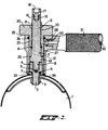
- This device comprises an exchange closure 2 with an external thread 3, which is designed in the same way as the original screw closure attached to the gas container 1, so that the exchange closure 2 can be screwed into the gas container 1 in its place.
- the exchange closure 2 has a cylindrical part 4 with a bore 5 which is provided with an internal thread.
- a steel-hard ball 6 rests on the bottom of this bore 5.
- An O-ring is arranged around the external thread 3, which secures the seal after filling.
- the threaded end 8 of a threaded pin 9 fits, which is provided over part of its length with an external thread 10, which has a larger diameter than the external thread 3, but has the same thread pitch.
- the external thread 10 is followed by a cylindrical section 11, which merges into a widened part 13 via a shoulder.
- a sealing ring 14 is arranged in the cylindrical section 11.
- the threaded pin 9 is provided with a bore 15 with an internal thread into which a threaded end 16 of a plug 17 fits, which is provided with an internal hexagon 18.
- a clamping element 20 is screwed onto the threaded pin 9 and is provided with an internal thread 21, a flange 22 and a cylindrical part 23.
- the clamping element 20 is surrounded by a filling sleeve 25, in the inner bore of which an O-ring 26 is arranged.
- a groove 27 is milled into the inner wall and ends in the filling opening 28.
- This filling opening 28 continues in a widened bore 29 (see FIG. 2 c), which is provided with an internal thread into which the threaded end 30 of a handle 31 fits, which has a filling channel 32 opening into the filling opening 28.
- the sleeve 25 has a sealing ring 33 on the underside.
- the replacement closure 2 is now placed on the gas container 1 and screwed into the external thread 3 of the gas container 1 by turning the clamping element 30.
- the longitudinal dimensions of the assembled parts are chosen so that when the sealing ring 33 seals at the lower end of the sleeve 25, an annular opening 35 remains free on the outer surface of the gas container 1 between the exchange closure 2 and the opening of the gas container 1. Nitrogen is then released under pressure from a suitable source, e.g. a high pressure nitrogen cylinder, introduced via the filling channel 32, the filling opening 28, the groove 27 and this opening 35 until the pressure in the gas container 1 has reached the desired final value.
- a suitable source e.g. a high pressure nitrogen cylinder
- the opening 35 in the gas container 1 is by holding the clamping element 20 and by tightening the Set screw 9 closed by means of a suitable tool. Since the external threads 3 and 10 have the same thread pitch, the interchangeable closure 2 is screwed into the filling opening when the setscrew 9 is tightened until the O-ring 7 lies sealingly against the outer surface of the gas container 1. The opening 35 is then closed.
- the tool is now disassembled by turning the threaded pin 9 to the left, whereby the surface of the part 8 detaches from the ball 7.
- the exchange closure 2 then remains in the gas container 1.
- the interchangeable closure 2 is finally additionally tightened with a suitable tool and closed with a plastic closure.
Landscapes
- Engineering & Computer Science (AREA)
- General Engineering & Computer Science (AREA)
- Mechanical Engineering (AREA)
- Physics & Mathematics (AREA)
- Fluid Mechanics (AREA)
- Filling Or Discharging Of Gas Storage Vessels (AREA)
- Closures For Containers (AREA)
- Manufacturing Of Electric Cables (AREA)
- Seal Device For Vehicle (AREA)
- Formation And Processing Of Food Products (AREA)
- Pens And Brushes (AREA)
- Sampling And Sample Adjustment (AREA)
Priority Applications (1)
| Application Number | Priority Date | Filing Date | Title |
|---|---|---|---|
| AT85201280T ATE34202T1 (de) | 1984-08-10 | 1985-08-07 | Fuelleinrichtung. |
Applications Claiming Priority (2)
| Application Number | Priority Date | Filing Date | Title |
|---|---|---|---|
| NL8402484A NL8402484A (nl) | 1984-08-10 | 1984-08-10 | Inrichting voor het met gas onder druk vullen van een met een schroefstop afgesloten houder, in het bijzonder de gasbol van een hydraupneumatische veerinrichting. |
| NL8402484 | 1984-08-10 |
Publications (2)
| Publication Number | Publication Date |
|---|---|
| EP0171126A1 true EP0171126A1 (fr) | 1986-02-12 |
| EP0171126B1 EP0171126B1 (fr) | 1988-05-11 |
Family
ID=19844316
Family Applications (1)
| Application Number | Title | Priority Date | Filing Date |
|---|---|---|---|
| EP85201280A Expired EP0171126B1 (fr) | 1984-08-10 | 1985-08-07 | Dispositif de remplissage |
Country Status (7)
| Country | Link |
|---|---|
| EP (1) | EP0171126B1 (fr) |
| AT (1) | ATE34202T1 (fr) |
| BE (1) | BE903017A (fr) |
| DE (2) | DE3562652D1 (fr) |
| ES (1) | ES288955Y (fr) |
| FR (1) | FR2568981B1 (fr) |
| NL (1) | NL8402484A (fr) |
Cited By (5)
| Publication number | Priority date | Publication date | Assignee | Title |
|---|---|---|---|---|
| EP0257682A3 (en) * | 1986-08-28 | 1988-10-05 | Tecnosir Snc Di Lazzari Carlo & Mella Maria | Valve and charging assembly to charge the spherical reservoirs of motor car suspensions with gas under pressure |
| EP0282626A3 (fr) * | 1987-03-18 | 1989-04-26 | Emmanuel Cafiso | Valve pour chambre pneumatique d'amortisseur hydropneumatique |
| FR2665489A1 (fr) * | 1990-07-31 | 1992-02-07 | Rougeux Jean | Gonfleur de spheres. |
| CN109139777A (zh) * | 2018-10-22 | 2019-01-04 | 中航飞机起落架有限责任公司 | 一种缓冲支柱的密封结构 |
| CN113124311A (zh) * | 2019-12-31 | 2021-07-16 | 西德福液压件(上海)有限公司 | 一种用于小型蓄能器安全填充氮气的装置 |
Citations (7)
| Publication number | Priority date | Publication date | Assignee | Title |
|---|---|---|---|---|
| GB264452A (en) * | 1926-01-18 | 1927-05-19 | Charles Sheppard Johann | Method and apparatus for filling and capping containers for gas under pressure |
| DE2000355A1 (de) * | 1970-01-07 | 1971-07-15 | Langen & Co | Hydrospeicher |
| DE2238356A1 (de) * | 1972-08-04 | 1974-02-14 | Fichtel & Sachs Ag | Fuellventil mit verschiebbarem ventilkoerper fuer hydropneumatische federungen von kraftfahrzeugen |
| DE2447343A1 (de) * | 1974-10-04 | 1976-04-15 | Teves Gmbh Alfred | Anschlusskopf eines gasfuellgeraetes |
| FR2331748A1 (fr) * | 1975-11-14 | 1977-06-10 | Bosch Gmbh Robert | Dispositif de remplissage de la chambre a gaz d'un reservoir sous pression |
| DE2843605A1 (de) * | 1978-10-06 | 1980-04-17 | Fichtel & Sachs Ag | Fuell- und pruefgeraet fuer druckraeume |
| DE3103952A1 (de) * | 1981-02-05 | 1982-08-12 | Boge Gmbh, 5208 Eitorf | Vorrichtung zum befuellen von schwingungsdaempfern |
-
1984
- 1984-08-10 NL NL8402484A patent/NL8402484A/nl not_active Application Discontinuation
- 1984-11-14 FR FR8417394A patent/FR2568981B1/fr not_active Expired
-
1985
- 1985-08-05 BE BE1/011310A patent/BE903017A/nl not_active IP Right Cessation
- 1985-08-07 DE DE8585201280T patent/DE3562652D1/de not_active Expired
- 1985-08-07 DE DE8522673U patent/DE8522673U1/de not_active Expired
- 1985-08-07 EP EP85201280A patent/EP0171126B1/fr not_active Expired
- 1985-08-07 AT AT85201280T patent/ATE34202T1/de not_active IP Right Cessation
- 1985-08-09 ES ES1985288955U patent/ES288955Y/es not_active Expired
Patent Citations (7)
| Publication number | Priority date | Publication date | Assignee | Title |
|---|---|---|---|---|
| GB264452A (en) * | 1926-01-18 | 1927-05-19 | Charles Sheppard Johann | Method and apparatus for filling and capping containers for gas under pressure |
| DE2000355A1 (de) * | 1970-01-07 | 1971-07-15 | Langen & Co | Hydrospeicher |
| DE2238356A1 (de) * | 1972-08-04 | 1974-02-14 | Fichtel & Sachs Ag | Fuellventil mit verschiebbarem ventilkoerper fuer hydropneumatische federungen von kraftfahrzeugen |
| DE2447343A1 (de) * | 1974-10-04 | 1976-04-15 | Teves Gmbh Alfred | Anschlusskopf eines gasfuellgeraetes |
| FR2331748A1 (fr) * | 1975-11-14 | 1977-06-10 | Bosch Gmbh Robert | Dispositif de remplissage de la chambre a gaz d'un reservoir sous pression |
| DE2843605A1 (de) * | 1978-10-06 | 1980-04-17 | Fichtel & Sachs Ag | Fuell- und pruefgeraet fuer druckraeume |
| DE3103952A1 (de) * | 1981-02-05 | 1982-08-12 | Boge Gmbh, 5208 Eitorf | Vorrichtung zum befuellen von schwingungsdaempfern |
Non-Patent Citations (1)
| Title |
|---|
| OLEODINAMICA-PNEUMATICA, Band 17, Nr. 2, Februar 1976, Seiten 50-54, Mailand, IT; "Qualche novita' sul mercato degli accessori" * |
Cited By (5)
| Publication number | Priority date | Publication date | Assignee | Title |
|---|---|---|---|---|
| EP0257682A3 (en) * | 1986-08-28 | 1988-10-05 | Tecnosir Snc Di Lazzari Carlo & Mella Maria | Valve and charging assembly to charge the spherical reservoirs of motor car suspensions with gas under pressure |
| EP0282626A3 (fr) * | 1987-03-18 | 1989-04-26 | Emmanuel Cafiso | Valve pour chambre pneumatique d'amortisseur hydropneumatique |
| FR2665489A1 (fr) * | 1990-07-31 | 1992-02-07 | Rougeux Jean | Gonfleur de spheres. |
| CN109139777A (zh) * | 2018-10-22 | 2019-01-04 | 中航飞机起落架有限责任公司 | 一种缓冲支柱的密封结构 |
| CN113124311A (zh) * | 2019-12-31 | 2021-07-16 | 西德福液压件(上海)有限公司 | 一种用于小型蓄能器安全填充氮气的装置 |
Also Published As
| Publication number | Publication date |
|---|---|
| FR2568981B1 (fr) | 1987-01-16 |
| ES288955U (es) | 1986-04-01 |
| BE903017A (nl) | 1986-02-05 |
| DE3562652D1 (en) | 1988-06-16 |
| DE8522673U1 (de) | 1985-11-14 |
| NL8402484A (nl) | 1986-03-03 |
| EP0171126B1 (fr) | 1988-05-11 |
| ATE34202T1 (de) | 1988-05-15 |
| ES288955Y (es) | 1986-12-01 |
| FR2568981A1 (fr) | 1986-02-14 |
Similar Documents
| Publication | Publication Date | Title |
|---|---|---|
| DE2210362C3 (de) | Selbsttätiges Druckregelventil | |
| DE2509200A1 (de) | Druckgefaess | |
| EP0171126B1 (fr) | Dispositif de remplissage | |
| EP0497193A2 (fr) | Elément de serrage et bride | |
| WO1995011452A1 (fr) | Dispositif compressible axialement pour chromatographie | |
| DE3925293C3 (de) | Vorrichtung zum lösbaren Verbinden einer Druckmittelleitung an einem Druckmittelanschluß | |
| DE1750053C3 (de) | Doppelrohrbruchsicherheitsventil | |
| EP0072023B1 (fr) | Appareil pour l'essai d'étanchéité d'objets creux | |
| EP0339525A2 (fr) | Dispositif pour l'obturation temporaire d'un bout d'un tuyau dans la domaine de tuyaux de chauffage à longue distance, de distribution d'eau et d'eaux usées | |
| EP1052159A2 (fr) | Coupe-circuit pour fluide sous pression pour direction assistée dans les positions extrêmes d'angle de braquage | |
| DE1806516A1 (de) | Kupplungsvorrichtung mit Absperreinrichtung zum Transport von Fluessigkeiten | |
| DE3230146A1 (de) | Vorrichtung zum pruefen der dichtigkeit von kuehlsystemen od. dgl. | |
| DE3213088A1 (de) | Von oben instandsetzbarer hydrospeicher | |
| EP0909917A2 (fr) | Système de stockage de gaz | |
| DE19756215C2 (de) | Schnell-Paß-System für Bauteile von Werkzeugmaschinen | |
| DE8601331U1 (de) | Ventil für die pneumatische Kammer eines hydropneumatischen Stossdämpfers | |
| DE2843605A1 (de) | Fuell- und pruefgeraet fuer druckraeume | |
| DE4327549A1 (de) | Verfahren zur Herstellung eines Keramikplungers für Pumpen u. dgl. | |
| DE3544782A1 (de) | Verschluss fuer einen benzineinfuellstutzen eines kraftfahrzeuges | |
| EP0328606A1 (fr) | Raccord a visser dans l'ouverture d'un recipient | |
| DE8620263U1 (de) | Membranventil | |
| DE2738522B2 (de) | Druckmittelbetriebener Arbeitszylinder | |
| DE3444443C2 (de) | Bierfaßlüfter mit Abdrückvorrichtung | |
| DE1182486B (de) | Absperrventil | |
| DE29605470U1 (de) | Ständer für stangenförmige Gegenstände |
Legal Events
| Date | Code | Title | Description |
|---|---|---|---|
| PUAI | Public reference made under article 153(3) epc to a published international application that has entered the european phase |
Free format text: ORIGINAL CODE: 0009012 |
|
| 17P | Request for examination filed |
Effective date: 19850807 |
|
| AK | Designated contracting states |
Designated state(s): AT BE CH DE FR GB IT LI LU NL SE |
|
| 17Q | First examination report despatched |
Effective date: 19860820 |
|
| GRAA | (expected) grant |
Free format text: ORIGINAL CODE: 0009210 |
|
| AK | Designated contracting states |
Kind code of ref document: B1 Designated state(s): AT BE CH DE FR GB IT LI LU NL SE |
|
| REF | Corresponds to: |
Ref document number: 34202 Country of ref document: AT Date of ref document: 19880515 Kind code of ref document: T |
|
| ITF | It: translation for a ep patent filed | ||
| GBT | Gb: translation of ep patent filed (gb section 77(6)(a)/1977) | ||
| REF | Corresponds to: |
Ref document number: 3562652 Country of ref document: DE Date of ref document: 19880616 |
|
| ET | Fr: translation filed | ||
| PLBE | No opposition filed within time limit |
Free format text: ORIGINAL CODE: 0009261 |
|
| STAA | Information on the status of an ep patent application or granted ep patent |
Free format text: STATUS: NO OPPOSITION FILED WITHIN TIME LIMIT |
|
| 26N | No opposition filed | ||
| ITTA | It: last paid annual fee | ||
| REG | Reference to a national code |
Ref country code: CH Ref legal event code: PUE Owner name: CITROTOOLS LIMITED |
|
| NLS | Nl: assignments of ep-patents |
Owner name: CITROTOOLS LIMITED TE NICOSIA, CYPRUS. |
|
| REG | Reference to a national code |
Ref country code: FR Ref legal event code: TP |
|
| REG | Reference to a national code |
Ref country code: GB Ref legal event code: 732 |
|
| ITPR | It: changes in ownership of a european patent |
Owner name: CESSIONE;CITROTOOLS LIMITED |
|
| EPTA | Lu: last paid annual fee | ||
| EAL | Se: european patent in force in sweden |
Ref document number: 85201280.6 |
|
| REG | Reference to a national code |
Ref country code: CH Ref legal event code: PFA Free format text: CITROTOOLS LIMITED TRANSFER- SPHERETOOLS LIMITED |
|
| NLT1 | Nl: modifications of names registered in virtue of documents presented to the patent office pursuant to art. 16 a, paragraph 1 |
Owner name: SPHERETOOLS LIMITED |
|
| NLUE | Nl: licence registered with regard to european patents |
Effective date: 19980220 |
|
| REG | Reference to a national code |
Ref country code: FR Ref legal event code: CD |
|
| REG | Reference to a national code |
Ref country code: FR Ref legal event code: CL |
|
| REG | Reference to a national code |
Ref country code: GB Ref legal event code: 732E |
|
| REG | Reference to a national code |
Ref country code: GB Ref legal event code: IF02 |
|
| PGFP | Annual fee paid to national office [announced via postgrant information from national office to epo] |
Ref country code: GB Payment date: 20040621 Year of fee payment: 20 |
|
| PGFP | Annual fee paid to national office [announced via postgrant information from national office to epo] |
Ref country code: DE Payment date: 20040824 Year of fee payment: 20 Ref country code: AT Payment date: 20040824 Year of fee payment: 20 |
|
| PGFP | Annual fee paid to national office [announced via postgrant information from national office to epo] |
Ref country code: SE Payment date: 20040826 Year of fee payment: 20 Ref country code: FR Payment date: 20040826 Year of fee payment: 20 Ref country code: CH Payment date: 20040826 Year of fee payment: 20 |
|
| PGFP | Annual fee paid to national office [announced via postgrant information from national office to epo] |
Ref country code: LU Payment date: 20040827 Year of fee payment: 20 |
|
| PGFP | Annual fee paid to national office [announced via postgrant information from national office to epo] |
Ref country code: NL Payment date: 20040830 Year of fee payment: 20 Ref country code: BE Payment date: 20040830 Year of fee payment: 20 |
|
| PG25 | Lapsed in a contracting state [announced via postgrant information from national office to epo] |
Ref country code: GB Free format text: LAPSE BECAUSE OF EXPIRATION OF PROTECTION Effective date: 20050806 |
|
| PG25 | Lapsed in a contracting state [announced via postgrant information from national office to epo] |
Ref country code: NL Free format text: LAPSE BECAUSE OF EXPIRATION OF PROTECTION Effective date: 20050807 |
|
| BE20 | Be: patent expired |
Owner name: *SPHERETOOLS LTD Effective date: 20050807 |
|
| REG | Reference to a national code |
Ref country code: CH Ref legal event code: PL Ref country code: GB Ref legal event code: PE20 |
|
| NLV7 | Nl: ceased due to reaching the maximum lifetime of a patent |
Effective date: 20050807 |
|
| EUG | Se: european patent has lapsed | ||
| BE20 | Be: patent expired |
Owner name: *SPHERETOOLS LTD Effective date: 20050807 |