EP0171267A2 - Streckrichteinrichtung - Google Patents
Streckrichteinrichtung Download PDFInfo
- Publication number
- EP0171267A2 EP0171267A2 EP85305504A EP85305504A EP0171267A2 EP 0171267 A2 EP0171267 A2 EP 0171267A2 EP 85305504 A EP85305504 A EP 85305504A EP 85305504 A EP85305504 A EP 85305504A EP 0171267 A2 EP0171267 A2 EP 0171267A2
- Authority
- EP
- European Patent Office
- Prior art keywords
- work roll
- cylinders
- roll
- guide
- support
- Prior art date
- Legal status (The legal status is an assumption and is not a legal conclusion. Google has not performed a legal analysis and makes no representation as to the accuracy of the status listed.)
- Withdrawn
Links
Images


Classifications
-
- B—PERFORMING OPERATIONS; TRANSPORTING
- B21—MECHANICAL METAL-WORKING WITHOUT ESSENTIALLY REMOVING MATERIAL; PUNCHING METAL
- B21D—WORKING OR PROCESSING OF SHEET METAL OR METAL TUBES, RODS OR PROFILES WITHOUT ESSENTIALLY REMOVING MATERIAL; PUNCHING METAL
- B21D1/00—Straightening, restoring form or removing local distortions of sheet metal or specific articles made therefrom; Stretching sheet metal combined with rolling
- B21D1/05—Stretching combined with rolling
Definitions
- the present invention relates to devices for flexing metal strips and, more particularly, devices for tension leveling metal strips by bending the strips around rolls having a relatively small diameter.
- a typical tension leveling line such as that disclosed in U.S. Patent No. 3,828,599 (With- row) and U.S. Patent No. 3,958,439 (Kawaguchi et al.), includes an entry drag bridle, an exit tension bridle and flexing means positioned between the entry and exit bridles.
- the strip is uncoiled by an uncoiling apparatus, passed through the tension leveling line, then recoiled on a recoiler.
- the flexing means typically includes a plurality of work rolls having a relatively small diameter about which the strip of material is passed.
- the rolls are positioned to extend transversely of the strip and are located so that the strip forms an undulating or zig-zag path as it passes from one work roll to the next.
- the entry drag bridle and exit tension bridle apply a tensile force to the strip as it passes through the flexing means, forcing the strip to conform to the small radiuses of the work rolls.
- tension leveling systems are capable of elongations of up to 2%, but most defects can be corrected by less than 1.0% elongation.
- U.S. Patent No. 3,260,093 shows a tension leveling apparatus in which a large diameter support roll is rotatably mounted on a frame and a work roll is similarly rotatably mounted on the same support frame directly above the support roll.
- U.S. Patent No. 3,513,677 (Polakowski) a tension leveling device is shown in which a work roll having a relatively small diameter is cradled between two larger support rolls. The work roll and both support rolls are rotatably attached to a frame.
- a problem inherent in the Miyamatsu device is that the fluid supporting the work roll must be supplied in high volume and will inevitably collect on the work material, necessitating additional time and equipment to effect subsequent removal of the fluid.
- the present invention is a tension leveling apparatus which includes a work roll having a relatively small diameter which is supported along its length by a single support roll having a relatively large diameter.
- the support roll is rotatably attached at a fixed position to a support frame and, therefore, its axis of rotation is fixed in position.
- the work roll is not fixed and is positionable relative to the rotational axis of the support roll by a feedback control system.
- the feedback control system senses the direction of the forces exerted upon the work roll by a strip passing over it and positions the work roll relative to the strip and the support roll so that the tangential components of these forces are in equilibrium. Consequently, a major portion of the forces exerted upon the work roll by the strip are applied along a radius of the support roll.
- the work roll is positioned so that the strip holds it against the support roll and does not require bearings to keep it in place. Therefore, the friction of the work roll against the support roll and against other components of the system is minimized.
- tension leveling apparatus of the present invention over prior art systems is that work rolls of an exceedingly small diameter--on the order of 1/4 inches to 3/4 inches (6.39mm to 19.05mm)--can be supported by a single support roll of a relatively large diameter--on the order of 5" (127mm)--without the necessity of expensive bearings or additional support rolls of an intermediate diameter to hold the work roll in position and prevent it from deflecting.
- a tension leveling apparatus which utilizes a work roll having a relatively small diameter, fewer work rolls are required in a tension leveling line to achieve a given amount of strip coil elongation.
- the use of small work rolls reduces the amount of strip tension required in a leveling line to generate the requisite bending stresses which cause the elongation of the strip.
- the feedback control system includes a guide tube having a hollow, cylindrical interior that encloses the support roll and end pieces which are rotatably attached to the support roll so that the guide tube may rotate relative to the support roll.
- the guide tube includes a longitudinal slot which is defined by opposing guide surfaces and is sized to receive the work roll so that the work roll contacts the enclosed support roll and protrudes beyond the outer surface of the guide tube to contact a strip coil passing over it.
- a feedback control device is operatively connected to the guide tube so that it senses a tangential component of the force exerted by a strip coil upon the work roll which tends to urge the work roll against one of the guide surfaces of the guide tube.
- the control device includes a pair of opposing, pressurized cylinders having pistons which are joined by a common rod that is linked to the guide tube. The control system selectively depressurizes one of the cylinders and pressurized the other so that the pistons urge the rod and guide tube to rotate in a direction counter to the tangential force applied against the guide tube by the work roll until that force component is minimized.
- control system design of the preferred embodiment is that the guide tube houses the work roll within a slot without the use of expensive anti-friction bearings which would add- to the cost of manufacturing the apparatus as well as the cost of maintaining the apparatus.
- a tension leveling apparatus in which a work roll having a relatively small diameter is supported by a single support roll having a relatively large diameter; a tension leveling apparatus in which a feedback control system continuously positions the work roll relative to the support roll in order to balance the tangential forces exerted upon the work roll by a strip coil passing over it so that the forces tending to displace the work roll are in equilibrium; a tension leveling apparatus in which the work roll is supported relative to a support roll without expensive and delicate anti-friction bearings; and a tension leveling apparatus which is relatively simple in construction and yet provides a high degree of strip elongation per unit.
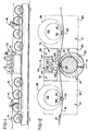
- a preferred embodiment of the tension leveling apparatus comprises five tension leveling modules 12.
- the apparatus also preferably includes a vertically positionable roller 13 which is used to remove any curvature in the strip 18 remaining after passing through the leveling modules 12.
- the tension leveling apparatus 10 is positioned between an entry drag bridle assembly 14 and an exit tension bridle assembly 16.
- the entry drag bridle 14 and exit tension bridle 16 are of well-known design and, together with the tension leveling apparatus 10, form a tension leveling line for leveling a strip 18 of metallic material such as steel, aluminum and the like.
- the strip 18 is unwound from a coil mounted on an uncoiler (not shown) and fed through the bridle 14.
- the strip 18 leaving the bridle 16 is rewound into a coil on a recoiler (not shown).
- each of the tension leveling modules 12 includes a cylindrical work roll 20, preferably having a diameter of between 0.25 inches and 0.75 inches (6.35mm and 19.05mm), a cylindrical support roll 22, and a feedback control system 24 which includes a guide tube 26 and controls 28.
- the modules 12 are arranged in alternating upright and inverted positions so that the strip 18 forms an undulating or zig-zag path as it passes through the tension leveling apparatus 10 and is bent partially around the circumference of each of the work rolls 20.
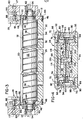
- the guide tube 26 is generally cylindrical in shape and includes a body portion 30 having an interior wall 32 which defines a cylindrical, longitudinal hollow interior 34 sized to receive the support roll 22.
- the guide tube body 30 includes a longitudinal slot 36 which is bordered by a pair of opposing guide surfaces 38, 40 (see also Fig. 6).
- the slot 36 is sized to receive the work roll 20, and the body is dimensioned to allow a lower portion of the work roll to contact the support roll 22 and an upper portion of the work roll to protrude outwardly beyond the outer surface of the body to contact a strip 18.
- the guide tube 26 includes a pair of opposing end plates 42, 44 which are attached to the ends of the body 30 by bolts 46.
- the end plates 42, 44 each include an upper opening 48, which is aligned with the slot 36 to permit the work roll 20 to be inserted or removed from the slot.
- the work roll 20 is captured within the slot 36 and openings 48 by end caps 50 which are threaded into the openings, and preferably are made of a low friction material such as bronze. In the alternative, antifriction bearings may be used.
- the support roll 22 consists of a cylindrical main body 52 and a pair of end stubs 54, 56 extending outwardly from the main body along a rotational axis A thereof (see Fig. 7).
- the main body preferably is made of hardened steel and has a polished outer surface.
- the main body 52 also includes a continuous, helical groove 58 which acts to remove accumulations of oxidation picked up from the strip passing over the work roll 20 and circulate lubricating fluid.
- the end stubs 54, 56 are rotatably attached to a support frame 60 by anti-friction bearings 62 of well-known design.
- the end plates 42, 44 of the guide tube 26 each include an opening 63 which includes bearings 64 that support the guide tube on the end stubs 54, 56, so that the guide tube may be rotated independently of the support roll 22.
- each of the end plates 42, 44 includes a yoke portion 66 which pivotally engages a cylindrical pin 68 which is a component of the feedback control system 24.
- a yoke portion 66 which pivotally engages a cylindrical pin 68 which is a component of the feedback control system 24.
- each of the controls 28 includes a pair of opposing cylinders 70, 72 which are divided into inner chambers 74, 76 and outer chambers 78, 80 by flexible diaphragms 82, 84, respectively.
- Each of the cylinders 70, 72 is made up of a base plate 86, and annular side wall 88, and an end plate 90 which is secured to the annular side wall by bolts 92.
- the outer peripheries of the diaphragms 82, 84 are clamped between the side walls 88 and base plates 86.
- Each of the cylinders 70, 72 includes a piston 94, 96, respectively, which comprises a head 98 attached to a rod 100 by a screw 102.
- the screws 102 pass through central orifices in the diaphragms 82, 84.
- the heads 98 and rod 100 are shaped to provide a clamping engagement with the diaphragms 82, 84.
- passages 104, 106 extend between the outer chambers 78, 80 and an outlet opening 108 which surrounds the pin 68.
- the outlet opening 108 is sized to allow the pin 68 to move slightly within it so that it may alternately block the orifices 110, 112 of the passages 104, 106, respectively.
- the cylinders 70, 72 are separated by walls 114, 116, which are spaced on either side of the rod 100, pin 68 and yoke portion 66.
- the side walls 116 of each control 28 arc attached to the frame 60 by screws 117 to fix the controls in position (see Fig. 3).
- a channel 118 joins inner chamber 74 to inner chamber 76, and extends through the base plates 86 of cylinders 70, 72, and through wall 114.
- a restriction 120 is placed within the channel 118 to act as a damping means to damp oscillations which might occur during operation or the controls 28.
- the central portion of the rod 100 includes a manifold 122 having a port 123 which is adapted to be connected to a flexible hose (not shown) connected to a source of pressurized air.
- the port 123 communicates with a passage 126 which is connected to the passages 104, 106 by orifices 124, 125, respectively, at a point adjacent to the orifices 110, 112. Pressurized air introduced to the port 123 flows through the passage 126 and orifices 124, 125, through passages 104, 106 to pressurize the outer chambers 78, 80 of the cylinders 70, 72.
- Pin 68 is a loose fit in the opening 108 allowing air in outer chambers 78, 80 to escape through orifices 110, 112.
- the orifices 124, 125, 110, 112 are sized such that the pressure of fluid entering port 123 is reduced by approximately 50% through each of the orifices 124, 125, and 50% through each of the orifices 110, 112.
- outer chambers 78, 80 are at the 'ame pressure, i.e., approximately 50% of the incoming fluid pressure at port 123.
- Outer chambers 78, 80 may alternately be depressurized by a slight movement of the pin 68 within the outlet opening 108, which would uncover one or the other of orifices 110, 112, and cover the other, thereby allowing the compressed air within the associated outer chamber to escape to the atmosphere. Concurrently, pressure in the other chamber would rise. The resulting differential would force manifold 122 to act against the initiating movement of pin 68 and move yoke 66, guide tube 26 and guide surfaces 38, 40 to position work roll 20 such that forces acting on it were again in equilibrium.
- a strip 18 of metal is unwound from a coil on an uncoiler (not shown) and threaded through the entry drag bridle 14, the tension leveling apparatus 10 and the exit tension bridle 16, as shown in Fig. 1.
- the end of the strip is again formed into a coil on a recoiling machine (not shown) of well-known design.
- proper tension is maintained by the entry drag bridle 14 and exit tension bridle 16, so that the strip is forced to bend partially around the relatively small circumferences of the work rolls 20 of the tension leveling modules 12. This bending causes a slight elongation of the shorter portions of the strip 18 and produces a strip having a substantially uniform length across its width, thereby removing any wavy sections which may have been present in the center of the strip or along its edges.
- the controls 28 function in the same fashion.
- the outer chamber 78 which has been pressurized by compressed air from the manifold 122 in the manner previously described, is depressurized as air escapes through the orifice 110.
- outer chamber 80 remains pressurized since the orifice 112 is closed by the pin 68. This imbalance allows the compressed air in chamber 80 to expand against the piston 98 and displace the pistons 94, 98, rod 100 and pin 68 in a direction toward the depressurized cylinder 70.
- the yoke portion 66 is rotated so that the guide tube 26 rotates in a direction counter to the force applied against guide surface 40.
- the position of the work roll 20 of each module 12 relative to the strip 18 changes until the pressure of the work rolls against the guide surfaces 38, 40 is substantially eliminated.
- the guide tube 26 and yoke 66 will rotate in a counterclockwise direction (as seen in Fig. 2) which applies pressure against the pins 68 to urge them against the orifices 110.
- the pressurized air expands against the head 98 of the piston 94 to displace the rod 100 and pin 68 is a direction counter to the force exerted by the work roll against the guide surface 38.
- Oscillations occurring in the guide tube 26 are damped out by the resistance to fluid flow from the inner chamber 74, 76 through channel 118 and restriction 120.
- the work rolls 20 of the tension leveling modules 12 are maintained in a state of equilibrium so that they are balanced upon and held against their respective support rolls 22 by the strip 18.
- the sum of all the forces exerted upon the work rolls 20 by the strip 18 acts along a line which passes through the centers of the work rolls 20 and the support rolls 22, so that the support rolls bear substantially the entire force exerted upon the work rolls, and the guide surfaces 38, 40 of the guide tube 26 bear a minimal amount of force, if any.
- FIG. 7 Another example of a feedback control system is shown in Fig. 7.
- the system 24' utilizes a work roll and support roll which are constructed and operate identically to the corresponding components previously discussed and shown in Figs. 1-5.
- the yoke portion 66' of the guide tube 22' is shaped to pivotally engage a pin 68' which is attached to a clevis 128.
- Clevis 128 is attached to a ball bearing screw 130.
- Screw 130 engages a ball bearing nut 132 which is rotated by reversible servo motor 134, and is attached to a stationary member such as support housing 60 (Fig. 3). The nut must be fixed in position relative to the guide tube 26'.
- a strain gauge 136 is mounted on the ball screw 130 and is connected to an amplifier 138.
- the amplifier 138 includes a comparator which compares the signal generated by the strain gauge 136 with a reference voltage, and generates a positive or negative signal when the screw 130 is placed under tension or compression, respectively.
- the amplifier is connected to the reversible motor 134.
- transducers could be used to sense the forces applied by the work roll 20 upon the guide surfaces 38, 40, and a control could be used to activate a double-acting cylinder or reversible motor to pivot the guide tube 26.
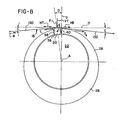
- Fig. 8 An analysis of the forces exerted by a strip 18 upon the work roll 20 and support roll 22 is best shown in Fig. 8. Briefly, the guide tube 26 is rotated by the feedback control system 24 in the manner previously described so that the work roll 20 is positioned relative to the support roll 22 and strip 18 such that the forces of the strip tangential to the work roll are balanced by the tangential component of the vertical forces upon the work roll resulting from strip tension.
- Angle C is the angle at which the strip 18 bends from a straight path.
- a force VT normal to the straight path of the strip, is exerted upon the work roll 20 by the strip 18 and is represented by the following equation:
- HT of VT which is the component of VT acting parallel and opposite to HB, acts upon the work roll 20 in a direction opposite to the Bending Losses and is calculated by the following equation:
- Angle D is the angle at which a line F, which passes through the center E of the work roll 20 and the center A of the support roll 22 makes with a line G which passes through the center A of the support roll and is perpendicular to the straight path of the strip, represented by line H.
- forces tangential to the work roll 20 are reduced to a very low value, thereby minimizing friction between the work roll and the guide surfaces 3R, 40 of the guide tube 26.
- the resultant of the forces acting upon the work roll 20 acts to hold the work roll against the support roll 22.
- angle D is automatically and continuously maintained at the value which results in equilibrium of work roll 20. Any change in tension, roll loss or strip velocity which upset this equilibrium will result in movement of work roll 20 towards one or the other guide surfaces 38 or 40 and produce a displacement of pin 68 to produce a response in the feedback control system to force the work roll 20 to a new position of equilibrium.
Landscapes
- Engineering & Computer Science (AREA)
- Mechanical Engineering (AREA)
- Straightening Metal Sheet-Like Bodies (AREA)
- Registering, Tensioning, Guiding Webs, And Rollers Therefor (AREA)
Applications Claiming Priority (2)
| Application Number | Priority Date | Filing Date | Title |
|---|---|---|---|
| US06/639,542 US4587822A (en) | 1984-08-10 | 1984-08-10 | Tension leveling apparatus |
| US639542 | 1996-04-29 |
Publications (2)
| Publication Number | Publication Date |
|---|---|
| EP0171267A2 true EP0171267A2 (de) | 1986-02-12 |
| EP0171267A3 EP0171267A3 (de) | 1987-04-22 |
Family
ID=24564527
Family Applications (1)
| Application Number | Title | Priority Date | Filing Date |
|---|---|---|---|
| EP85305504A Withdrawn EP0171267A3 (de) | 1984-08-10 | 1985-08-01 | Streckrichteinrichtung |
Country Status (3)
| Country | Link |
|---|---|
| US (1) | US4587822A (de) |
| EP (1) | EP0171267A3 (de) |
| JP (1) | JPH0688076B2 (de) |
Families Citing this family (6)
| Publication number | Priority date | Publication date | Assignee | Title |
|---|---|---|---|---|
| JP2633902B2 (ja) * | 1988-04-27 | 1997-07-23 | 株式会社日立製作所 | 矯正機,矯正装置,及び矯正方法並びに矯正ライン設備 |
| JP3427863B2 (ja) * | 1994-12-27 | 2003-07-22 | 住友金属鉱山株式会社 | 電解用種板の歪み矯正方法 |
| JP4837173B2 (ja) * | 2001-01-30 | 2011-12-14 | 株式会社岡村製作所 | ローラコンベアにおける搬送物移載装置 |
| US6668610B2 (en) * | 2001-12-27 | 2003-12-30 | Alcan International Limited | Method for continuous tension leveling of aluminum strip |
| US20070066777A1 (en) * | 2004-09-03 | 2007-03-22 | Bzowej Eugene I | Methods for producing crosslinkable oligomers |
| US20090297323A1 (en) * | 2008-05-30 | 2009-12-03 | Genesis Worldwide Ii, Inc. | Method and apparatus for stacking sheet materials |
Family Cites Families (11)
| Publication number | Priority date | Publication date | Assignee | Title |
|---|---|---|---|---|
| BE651588A (de) * | 1963-08-07 | |||
| US3260093A (en) * | 1964-04-01 | 1966-07-12 | Natalis H Polakowski | Strip flattening device |
| BE668383A (de) * | 1964-08-17 | |||
| US3344637A (en) * | 1965-02-01 | 1967-10-03 | Natalis H Polakowski | Strip rolling mill system and process |
| US3513677A (en) * | 1967-08-02 | 1970-05-26 | Natalis H Polakowski | Metal strip processing machine |
| US3828599A (en) * | 1971-11-09 | 1974-08-13 | Prod Machinery Corp | Apparatus and method for leveling metal strip |
| DD100168A1 (de) * | 1972-12-06 | 1973-09-12 | ||
| US3812701A (en) * | 1972-12-14 | 1974-05-28 | Toyo Kohan Co Ltd | Method and an apparatus of leveling a metal strip |
| US3812697A (en) * | 1973-02-05 | 1974-05-28 | Toyo Kohan Co Ltd | Method and an apparatus of leveling a metal strip |
| JPS52837B2 (de) * | 1973-05-31 | 1977-01-11 | ||
| DE2536582C3 (de) * | 1975-08-16 | 1979-08-09 | Bwg Bergwerk- Und Walzwerk-Maschinenbau Gmbh, 4100 Duisburg | Wechseltraverse |
-
1984
- 1984-08-10 US US06/639,542 patent/US4587822A/en not_active Expired - Fee Related
-
1985
- 1985-08-01 EP EP85305504A patent/EP0171267A3/de not_active Withdrawn
- 1985-08-10 JP JP60175005A patent/JPH0688076B2/ja not_active Expired - Lifetime
Also Published As
| Publication number | Publication date |
|---|---|
| JPS6188921A (ja) | 1986-05-07 |
| EP0171267A3 (de) | 1987-04-22 |
| US4587822A (en) | 1986-05-13 |
| JPH0688076B2 (ja) | 1994-11-09 |
Similar Documents
| Publication | Publication Date | Title |
|---|---|---|
| KR100258660B1 (ko) | 조강재의 안내 방법 및 그 장치 | |
| US4222255A (en) | Rolling device having at least one controlled deflection roll | |
| CN106488810B (zh) | 自激第三八度轧机振动的处理阻尼 | |
| US4212504A (en) | Backing device for a working roll of a roll stand | |
| KR910011349A (ko) | 압연기용 두께 제어 시스템 | |
| EP0534602B1 (de) | Walzwerk und Walzverfahren | |
| US4249290A (en) | Controlled deflection roll | |
| US4587822A (en) | Tension leveling apparatus | |
| KR890011636A (ko) | 압연기와 압연기장치 | |
| KR930010335B1 (ko) | 압연기 및 압연방법 | |
| US3648342A (en) | Movable combination of rolls | |
| US3834202A (en) | Metal strip straightening machine | |
| KR20020016781A (ko) | 조절 가능한 모니터링 가이드 | |
| US3328992A (en) | Method of and apparatus for obtaining flat metallic strip | |
| JPS5994509A (ja) | 帯材用の圧延機 | |
| US4324122A (en) | Metal strip cold-reduction mill | |
| US3425249A (en) | Rolling mill | |
| GB1584273A (en) | Methods of and mills for rolling metal strip | |
| US20100162784A1 (en) | Flattening device | |
| US4353237A (en) | Method of rolling strip | |
| EP0479750A1 (de) | Vorrichtung zum Anstellen der Walzkaliber in einem Walzgerüst | |
| EP0508475A2 (de) | Streckrollen-Richtmaschine | |
| JPS5817683B2 (ja) | ロ−ル圧延台の作動ロ−ル用バックアップ装置 | |
| SE527607C2 (sv) | Metod och anordning för trådmatning | |
| US3812701A (en) | Method and an apparatus of leveling a metal strip |
Legal Events
| Date | Code | Title | Description |
|---|---|---|---|
| PUAI | Public reference made under article 153(3) epc to a published international application that has entered the european phase |
Free format text: ORIGINAL CODE: 0009012 |
|
| AK | Designated contracting states |
Designated state(s): DE FR GB IT |
|
| PUAL | Search report despatched |
Free format text: ORIGINAL CODE: 0009013 |
|
| AK | Designated contracting states |
Kind code of ref document: A3 Designated state(s): DE FR GB IT |
|
| STAA | Information on the status of an ep patent application or granted ep patent |
Free format text: STATUS: THE APPLICATION IS DEEMED TO BE WITHDRAWN |
|
| 18D | Application deemed to be withdrawn |
Effective date: 19871023 |
|
| RIN1 | Information on inventor provided before grant (corrected) |
Inventor name: BRADLEE, CHARLES R. |