EP0171364B1 - Dentale Verankerung für herausnehmbare Teilprothese - Google Patents
Dentale Verankerung für herausnehmbare Teilprothese Download PDFInfo
- Publication number
- EP0171364B1 EP0171364B1 EP19850830142 EP85830142A EP0171364B1 EP 0171364 B1 EP0171364 B1 EP 0171364B1 EP 19850830142 EP19850830142 EP 19850830142 EP 85830142 A EP85830142 A EP 85830142A EP 0171364 B1 EP0171364 B1 EP 0171364B1
- Authority
- EP
- European Patent Office
- Prior art keywords
- fitting
- fact
- cylindrical body
- prosthesis
- runners
- Prior art date
- Legal status (The legal status is an assumption and is not a legal conclusion. Google has not performed a legal analysis and makes no representation as to the accuracy of the status listed.)
- Expired
Links
Images
Classifications
-
- A—HUMAN NECESSITIES
- A61—MEDICAL OR VETERINARY SCIENCE; HYGIENE
- A61C—DENTISTRY; APPARATUS OR METHODS FOR ORAL OR DENTAL HYGIENE
- A61C13/00—Dental prostheses; Making same
- A61C13/225—Fastening prostheses in the mouth
- A61C13/273—Fastening prostheses in the mouth removably secured to residual teeth by using bolts or locks
Definitions
- the present invention relates to a coupling for partial dentures, removable.
- a removable partial prosthesis is used when the number and the arrangement of the remaining teeth of an arch do not allow the placement of a fixed prosthesis.
- a removable prosthesis includes a support gutter on the bones of the jaw as well as an anchoring system to at least one pillar, by means of hooks or a precision coupling composed of two slides with male-type attachments. female, one welded to a crown cast on the abutment tooth and the other incorporated into the prosthesis.
- Document FR-A-1,134,137 discloses a coupling with a retention head carried by a shaft mounted to slide in the bore of the prosthesis so as to be able to approach or move away from the abutment tooth and with a cheek mounted to slide on this shaft and pushed outwards by a spring which rests on a nut whose displacement makes it possible to adjust the tension of the spring.
- This known coupling nevertheless requires repeated and difficult adjustment operations, which involve dismantling the various components each time and maneuvering the nut several times; in the case of a two-part prosthesis with the abutment tooth interposed, this maneuver seems very difficult.
- the main objective of the present invention is to eliminate the above-mentioned drawbacks.
- the invention solves the problem of producing a precision coupling for a removable partial dental prosthesis, easy to use and with variable operation.
- the compression that is to say the retentive force
- the compression is adjustable from a point of the alveolar gutter of the prosthesis, by rotation of a member about its own axis, which is inclined with respect to the direction of translation of the retaining element of the slide incorporated in the prosthesis and the operating characteristics of the device can be modified by changing only the conformation of the retentive head which must be inserted in the slide welded to the abutment tooth, without changing the general appearance of the prosthesis.
- the advantages obtained by virtue of the present invention essentially consist in the fact that it is possible to precisely adjust the containment of the anchorage by acting on the head of a screw which appears on the surface of the alveolar gutter of the prosthesis; that said adjustment is obtained without having to disassemble the parts making up the slide of the coupling incorporated in the prosthesis; that the components of the slide incorporated in the prosthesis are held mutually in place without locking clips; that the containment sheath of the components of the slide incorporated in the prosthesis can be replaced in the event of possible wear by galvanic erosion; that the retaining head is an interchangeable element whose shape is related to the desired operating characteristic of the coupling; that the head can be removed from the male element while remaining attached to the female element of the coupling; that a coupling produced in accordance with the invention is simple in construction, easy to apply and safe to operate, even after a long period of use.
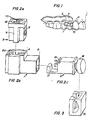
- Figure 1 shows the overall view of a partial prosthesis with removable coupling produced in accordance with the invention, in the position of use;
- Figures 2A-2B-2C show, in enlarged exploded axonometric perspective, the three parts making up the male element of the hitch of Figure 1;
- Figure 3 shows, in enlarged axonometric perspective, a female element of the coupling of Figure 1;
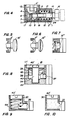
- Figure 4 shows, in vertical section, the components of Figures 2A-2B-2C after assembly, to form a rigid coupling;
- Figure 5 shows the detail of a retentive head to form a semi-rigid hitch;
- Figure 6 shows the detail of a retentive head to form an elastic coupling;
- Figure 7 shows the detail of a retentive pusher head;
- Figure 8 shows, in vertical section, the components of the female element, to form a simplified push hitch, according to the invention;
- Figure 9 shows, in vertical section, the components of the female element, to form another simplified push hitch
- the coupling for removable prosthesis illustrated in the attached figures is composed of a sliding element, intended to be integrated into the prosthesis, and of a sliding element, intended to be fixed, in a traditional way, on a tooth. pillar.
- the head 2 comprises a sheath 2 ′ casing, open at one of its vertical ends and with a central hole, in correspondence with the other vertical end; this sheath can be placed, precisely, in the horizontal wing of the envelope 1 and is provided with a flange 17 and a groove 21; an axial pivot 14 with thread 15 passes through said hole 24, integrating with an external, retentive head 16 and exits, at the opposite end of the sheath, with a point 10, contracted and of square section for mounting therein a bevel gear 5; on the thread 15 of said pivot 14 is screwed a plate 19, square, with interposition of a spring 18.
- the aforementioned casing 3 comprises a body 6 provided with two longitudinal slides 9, a transverse projection 8, intended to be inserted in the corresponding groove 21 of the head 2, and a cavity 7 where the flange should be inserted correspondent 17 of head 2; said body 6 is further suitably hollowed out so as to be able to contain a cylindrical body 4 'provided in its lower part with a bevel gear 4 intended to retain the bevel gear 5 mentioned above; said body 4 ′ is further provided with a notch 12 making it possible to control the rotation of the pinion 4 and an internal thread 13 making it possible to facilitate the extraction of the casing 3 from the casing 1.
- Said envelope is a square section housing body with a right angle development, open at its upper horizontal end and at its vertical lateral end, provided with two vertical grooves 20 allowing the insertion of the corresponding slides 9 of the casing 3; its two wings, the horizontal and the vertical, allow the insertion, respectively, of the head 2 and of the casing 3, which must be inserted in this order.
- To dismantle the device first extract the casing 3 and then the head 2.
- the adjustment of the retentive force takes place by rotating the pinion 4, in one direction or the other, by acting with a screwdriver on the notch 12 of the body 4 ', in fact, by doing so, the rotation is caused pinion 5 and pivot 14 as well as the simultaneous translation of the plate 19 along the axis of the pivot 14, and the latter, by compressing, more or less, the spring 18, determines the desired tensile force of the head 16.
- the axis of rotation of the pinion 4 is inclined relative to the axis of the pivot 14, at an angle equal or not to 90 °, so however that the base of the body 4 ' with the notch 12 is flush with the surface of the alveolar gutter of the prosthesis.
- the axes of the pinion 4 and the pivot 14 with the retaining head 16 may be oblique to each other, that is to say that they may not be in the same plane. ; in this case the transmission of the movement will be obtained by means of an endless screw, in place of the pinion 4, and of a helical tooth wheel in place of the pinion 5.
- the head 16 will be cylindrical and with flat bases and the sheath head will be flat, as shown in Figure 4 of the accompanying drawings, so that the head 16 can be inserted into the groove of the female slide of the coupling, without possibility of movement.
- the head 16 ′ will be cylindrical and with slightly convex bases and the head 2 ′ of the sheath 2 will be slightly convex, as shown in FIG. 5 of the attached drawings, so that the head can be inserted into the groove of the female slide of the coupling, with a certain, limited possibility of rotation.
- the head 16 In case of elastic coupling, that is to say hinged, with vertical and horizontal rotation, the head 16 "will be cylindrical with strongly convex bases and the head 2" of the sheath 2 will be strongly convex, as shown in Figure 6 of the accompanying drawings, so that the head 16 can be inserted into the groove of the female slide of the hitch with great freedom of rotation.
- the retaining head 16 with its corresponding pivot 14 can be replaced by a pusher 16 "', as shown in Figure 7 of the accompanying drawings.
- Said body 40 ′ and said pivot 40 are conveniently connected to the housing 30, by means of machines known as such, such as for example elastic rings 41.
- Said body 40 is further provided with a notch 42 in dovetail, allowing its rotation to be controlled and its extraction from the housing 30.
Landscapes
- Health & Medical Sciences (AREA)
- Oral & Maxillofacial Surgery (AREA)
- Dentistry (AREA)
- Epidemiology (AREA)
- Life Sciences & Earth Sciences (AREA)
- Animal Behavior & Ethology (AREA)
- General Health & Medical Sciences (AREA)
- Public Health (AREA)
- Veterinary Medicine (AREA)
- Dental Prosthetics (AREA)
Claims (11)
Priority Applications (1)
| Application Number | Priority Date | Filing Date | Title |
|---|---|---|---|
| AT85830142T ATE47028T1 (de) | 1984-06-11 | 1985-06-10 | Dentale verankerung fuer herausnehmbare teilprothese. |
Applications Claiming Priority (4)
| Application Number | Priority Date | Filing Date | Title |
|---|---|---|---|
| IT1740684 | 1984-06-11 | ||
| IT1740684A IT1229045B (it) | 1984-06-11 | 1984-06-11 | Ancoraggio per protesi dentali parziali amovibili con scatola di regolazione di forza ritentiva e funzioni variabili di collegamento |
| IT8417413A IT1229048B (it) | 1984-11-20 | 1984-11-20 | Ancoraggio per protesi dentali parziali amovibili con sistema esposto di regolazione di tenuta e funzioni variabili di collegamento |
| IT1741384 | 1984-11-20 |
Publications (3)
| Publication Number | Publication Date |
|---|---|
| EP0171364A2 EP0171364A2 (de) | 1986-02-12 |
| EP0171364A3 EP0171364A3 (en) | 1987-05-06 |
| EP0171364B1 true EP0171364B1 (de) | 1989-10-11 |
Family
ID=26326933
Family Applications (1)
| Application Number | Title | Priority Date | Filing Date |
|---|---|---|---|
| EP19850830142 Expired EP0171364B1 (de) | 1984-06-11 | 1985-06-10 | Dentale Verankerung für herausnehmbare Teilprothese |
Country Status (2)
| Country | Link |
|---|---|
| EP (1) | EP0171364B1 (de) |
| DE (1) | DE3573526D1 (de) |
Families Citing this family (1)
| Publication number | Priority date | Publication date | Assignee | Title |
|---|---|---|---|---|
| FR2656664A1 (fr) * | 1990-01-03 | 1991-07-05 | Coulange Michel | Procede d'accrochage par elements autobloquants, dispositif mettant en óoeuvre ce procede d'accrochage, et appareil utilisant un tel dispositif. |
Family Cites Families (5)
| Publication number | Priority date | Publication date | Assignee | Title |
|---|---|---|---|---|
| FR1066607A (fr) * | 1952-07-19 | 1954-06-08 | Dispositif de fixation pour des prothèses dentaires partielles leur permettant une légère mobilité dans plusieurs sens | |
| FR1134137A (fr) * | 1955-07-19 | 1957-04-08 | Dispositif pour la fixation de prothèses à des dents voisines | |
| FR1492847A (fr) * | 1966-02-25 | 1967-08-25 | Dispositif de maintien des prothèses dentaires dans la bouche d'édentés partiels | |
| FR2094650A5 (de) * | 1970-06-29 | 1972-02-04 | Narboru Victor | |
| IT1089491B (it) * | 1977-11-11 | 1985-06-18 | Boesmi Natalino | Congegno di ritegnoa tassello elastico per protesi amovibili in odontoiatria |
-
1985
- 1985-06-10 EP EP19850830142 patent/EP0171364B1/de not_active Expired
- 1985-06-10 DE DE8585830142T patent/DE3573526D1/de not_active Expired
Also Published As
| Publication number | Publication date |
|---|---|
| DE3573526D1 (en) | 1989-11-16 |
| EP0171364A2 (de) | 1986-02-12 |
| EP0171364A3 (en) | 1987-05-06 |
Similar Documents
| Publication | Publication Date | Title |
|---|---|---|
| EP0986350B1 (de) | Implantat, insbesondere zum einsatz eines wirbelkörpers in der wirbelsäulenchirurgie | |
| EP0436697B1 (de) | Vorrichtung zum geraderichten, befestigen, zusammendrücken und ausdehnen der wirbelsäule | |
| EP0962287B1 (de) | Mit einer Verriegelungsvorrichtung versehenes Antriebswerkzeug | |
| EP0971639B1 (de) | Vorrichtung zur wirbelsäulen-osteosythese mit versetzt angeordnetem zwischenwirbelverankerungsstab | |
| EP2983623B1 (de) | Abnehmbarer griff mit einer vorrichtung für lösbare montage | |
| FR2729557A1 (fr) | Implant de type cage intersomatique, et instrumentation et procede pour sa pose | |
| FR2629977A1 (fr) | Ensemble demontable de materiel electrique ou electronique comprenant un boitier et son logement | |
| EP3609362B1 (de) | Armbandglied | |
| EP1034750B1 (de) | Zahnimplantat mit Mitteln zur Verhinderung der Drehbewegung der Aufbaustruktur | |
| EP3756501A1 (de) | Befestigungsvorrichtung für armband | |
| FR3012319A1 (fr) | Dispositif de liaison entre un implant dentaire et une prothese dentaire trans-fixee | |
| EP0230846B1 (de) | Winkelstück für endodontisches Instrument zum Halten eines Durchbohrwerkzeuges einer Feile oder eines anderen Werkzeuges | |
| WO1988008691A1 (fr) | Fixateur externe pour chirurgie osseuse | |
| EP0687448A1 (de) | Femoral-patellare Prothese und Hilfseinrichtung zur Herstellung von trochlearen Abdrücken zur Aufnahme einer solchen Prothese | |
| FR2808992A1 (fr) | Analogue de laboratoire pour prothese dentaire | |
| FR2500295A1 (fr) | Dispositif de contention d'une prothese dentaire amovible | |
| FR2935620A1 (fr) | Outil pour l'ebavurage de percages, avec des lames de coupe disposees par paire et un porte-outil entraine en rotation | |
| EP1929975B1 (de) | Schraubenzieher für den Einsatz im zahnmedizinischen oder chirurgischen Bereich | |
| EP0171364A2 (de) | Dentale Verankerung für herausnehmbare Teilprothese | |
| FR2587613A1 (fr) | Dispositif pour retenir une prothese dentaire amovible | |
| FR2656212A1 (fr) | Systeme d'enclouage centro-medullaire pour immobiliser une fracture d'un os. | |
| FR2690760A1 (fr) | Charnière élastique sans vis apparente. | |
| FR2720624A1 (fr) | Implant dentaire et éléments auxiliaires amovibles s'y adaptant. | |
| CH632145A5 (fr) | Piece a main dentaire. | |
| FR2489127A1 (fr) | Dispositif d'ouverture de mollusques fixable sur un support |
Legal Events
| Date | Code | Title | Description |
|---|---|---|---|
| PUAI | Public reference made under article 153(3) epc to a published international application that has entered the european phase |
Free format text: ORIGINAL CODE: 0009012 |
|
| AK | Designated contracting states |
Designated state(s): AT BE CH DE FR GB IT LI LU NL SE |
|
| PUAL | Search report despatched |
Free format text: ORIGINAL CODE: 0009013 |
|
| AK | Designated contracting states |
Kind code of ref document: A3 Designated state(s): AT BE CH DE FR GB IT LI LU NL SE |
|
| 17P | Request for examination filed |
Effective date: 19870404 |
|
| 17Q | First examination report despatched |
Effective date: 19881021 |
|
| GRAA | (expected) grant |
Free format text: ORIGINAL CODE: 0009210 |
|
| AK | Designated contracting states |
Kind code of ref document: B1 Designated state(s): AT BE CH DE FR GB IT LI LU NL SE |
|
| REF | Corresponds to: |
Ref document number: 47028 Country of ref document: AT Date of ref document: 19891015 Kind code of ref document: T |
|
| ITF | It: translation for a ep patent filed | ||
| GBT | Gb: translation of ep patent filed (gb section 77(6)(a)/1977) | ||
| REF | Corresponds to: |
Ref document number: 3573526 Country of ref document: DE Date of ref document: 19891116 |
|
| PLBE | No opposition filed within time limit |
Free format text: ORIGINAL CODE: 0009261 |
|
| STAA | Information on the status of an ep patent application or granted ep patent |
Free format text: STATUS: NO OPPOSITION FILED WITHIN TIME LIMIT |
|
| 26N | No opposition filed | ||
| ITTA | It: last paid annual fee | ||
| EPTA | Lu: last paid annual fee | ||
| EAL | Se: european patent in force in sweden |
Ref document number: 85830142.7 |
|
| PGFP | Annual fee paid to national office [announced via postgrant information from national office to epo] |
Ref country code: SE Payment date: 20000607 Year of fee payment: 16 |
|
| PGFP | Annual fee paid to national office [announced via postgrant information from national office to epo] |
Ref country code: GB Payment date: 20000615 Year of fee payment: 16 |
|
| PGFP | Annual fee paid to national office [announced via postgrant information from national office to epo] |
Ref country code: AT Payment date: 20000626 Year of fee payment: 16 |
|
| PGFP | Annual fee paid to national office [announced via postgrant information from national office to epo] |
Ref country code: LU Payment date: 20000627 Year of fee payment: 16 |
|
| PGFP | Annual fee paid to national office [announced via postgrant information from national office to epo] |
Ref country code: NL Payment date: 20000630 Year of fee payment: 16 |
|
| PGFP | Annual fee paid to national office [announced via postgrant information from national office to epo] |
Ref country code: FR Payment date: 20000703 Year of fee payment: 16 |
|
| PG25 | Lapsed in a contracting state [announced via postgrant information from national office to epo] |
Ref country code: FR Free format text: LAPSE BECAUSE OF NON-PAYMENT OF DUE FEES Effective date: 20010228 |
|
| REG | Reference to a national code |
Ref country code: FR Ref legal event code: ST |
|
| PG25 | Lapsed in a contracting state [announced via postgrant information from national office to epo] |
Ref country code: LU Free format text: LAPSE BECAUSE OF NON-PAYMENT OF DUE FEES Effective date: 20010610 Ref country code: GB Free format text: LAPSE BECAUSE OF NON-PAYMENT OF DUE FEES Effective date: 20010610 Ref country code: AT Free format text: LAPSE BECAUSE OF NON-PAYMENT OF DUE FEES Effective date: 20010610 |
|
| PG25 | Lapsed in a contracting state [announced via postgrant information from national office to epo] |
Ref country code: SE Free format text: LAPSE BECAUSE OF NON-PAYMENT OF DUE FEES Effective date: 20010611 |
|
| PG25 | Lapsed in a contracting state [announced via postgrant information from national office to epo] |
Ref country code: NL Free format text: LAPSE BECAUSE OF NON-PAYMENT OF DUE FEES Effective date: 20020101 |
|
| GBPC | Gb: european patent ceased through non-payment of renewal fee |
Effective date: 20010610 |
|
| EUG | Se: european patent has lapsed |
Ref document number: 85830142.7 |
|
| NLV4 | Nl: lapsed or anulled due to non-payment of the annual fee |
Effective date: 20020101 |
|
| PGFP | Annual fee paid to national office [announced via postgrant information from national office to epo] |
Ref country code: BE Payment date: 20020731 Year of fee payment: 18 |
|
| PGFP | Annual fee paid to national office [announced via postgrant information from national office to epo] |
Ref country code: CH Payment date: 20020823 Year of fee payment: 18 |
|
| PG25 | Lapsed in a contracting state [announced via postgrant information from national office to epo] |
Ref country code: LI Free format text: LAPSE BECAUSE OF NON-PAYMENT OF DUE FEES Effective date: 20030630 Ref country code: CH Free format text: LAPSE BECAUSE OF NON-PAYMENT OF DUE FEES Effective date: 20030630 Ref country code: BE Free format text: LAPSE BECAUSE OF NON-PAYMENT OF DUE FEES Effective date: 20030630 |
|
| PGFP | Annual fee paid to national office [announced via postgrant information from national office to epo] |
Ref country code: DE Payment date: 20031129 Year of fee payment: 19 |
|
| BERE | Be: lapsed |
Owner name: *MENICAGLI IVANO Effective date: 20030630 |
|
| REG | Reference to a national code |
Ref country code: CH Ref legal event code: PL |
|
| PG25 | Lapsed in a contracting state [announced via postgrant information from national office to epo] |
Ref country code: DE Free format text: LAPSE BECAUSE OF NON-PAYMENT OF DUE FEES Effective date: 20050101 |