EP0171505A2 - Agencement du distributeur pour un moteur à combustion interne - Google Patents
Agencement du distributeur pour un moteur à combustion interne Download PDFInfo
- Publication number
- EP0171505A2 EP0171505A2 EP85103769A EP85103769A EP0171505A2 EP 0171505 A2 EP0171505 A2 EP 0171505A2 EP 85103769 A EP85103769 A EP 85103769A EP 85103769 A EP85103769 A EP 85103769A EP 0171505 A2 EP0171505 A2 EP 0171505A2
- Authority
- EP
- European Patent Office
- Prior art keywords
- distributor
- camshaft
- driver
- rotor
- ignition
- Prior art date
- Legal status (The legal status is an assumption and is not a legal conclusion. Google has not performed a legal analysis and makes no representation as to the accuracy of the status listed.)
- Ceased
Links
Images
Classifications
-
- F—MECHANICAL ENGINEERING; LIGHTING; HEATING; WEAPONS; BLASTING
- F02—COMBUSTION ENGINES; HOT-GAS OR COMBUSTION-PRODUCT ENGINE PLANTS
- F02P—IGNITION, OTHER THAN COMPRESSION IGNITION, FOR INTERNAL-COMBUSTION ENGINES; TESTING OF IGNITION TIMING IN COMPRESSION-IGNITION ENGINES
- F02P7/00—Arrangements of distributors, circuit-makers or -breakers, e.g. of distributor and circuit-breaker combinations or pick-up devices
- F02P7/10—Drives of distributors or of circuit-makers or -breakers
Definitions
- the invention relates to an ignition distributor arrangement on internal combustion engines, in which the ignition distributor is fastened to the housing of the internal combustion engine and is driven by a camshaft, the ignition distributor being aligned axially with the camshaft and having a distributor rotor provided with a cylindrical basic shape and having a cylindrical cylinder connected downstream of the camshaft Driver cooperates.
- the object of the invention is to provide an improved ignition distributor arrangement in which the fastening of the driver and the distributor rotor reliably withstands the vibrations occurring during operation of the internal combustion engine.
- connection designed in this way - driver and distributor rotor - is not solved by the speeds and vibrations occurring during operation of the internal combustion engine. This is supported by the symmetrical mass distribution on the distributor rotor (avoiding unbalance). Due to the relatively close approach of the outer diameter of the flange to the diameter of the opening, the distributor rotor space is effectively covered with respect to the toothed belt wheel space, whereby an additional dust cap can be omitted.
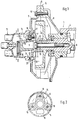
- An internal combustion engine 1 with valves, not shown, comprises an overhead camshaft 2, which is supported with its one end region 3 in an insert 5 assigned to a camshaft housing 4.
- the insert 5 is part of a housing 6 which surrounds a toothed belt wheel 7 which serves to drive the camshaft 2.
- the housing 6 is formed by a receiving part 8 connected to the insert 5 and a closure part 9, which are assembled in a vertical plane A-A and connected by means of screws 10.
- An ignition distributor 11 is arranged coaxially with the longitudinal center axis B-B of the camshaft 2 and is driven by the latter.
- a cylindrical driver 12 is provided downstream of the camshaft 2 and also the toothed belt wheel 7, which is connected to the camshaft 2 in a rotationally and axially secure manner together with the toothed belt wheel 7, a screw 13 serving to axially secure the driver 12 and the toothed belt wheel 7. Further details can be found in DE-PS 3 027 695.
- the ignition distributor 11 comprises a distributor housing 14 and a distributor rotor 15, which has a cylindrical basic shape and an asymmetrical contact finger 16.
- the driver 12 has, on the side facing the distributor rotor 15, a flange 17, which runs transversely to the longitudinal center axis BB of the camshaft 2 and has a corresponding one Dating extension 18 of the distributor rotor 15 is introduced.
- the driver 12 and the distributor rotor 14 are connected in the region of the flange 17 and the extension 18 via a screw 19, the longitudinal central axis CC of which extends parallel to the longitudinal central axis BB of the camshaft 2.
- the circular outer diameter E of the flange 17 is only slightly smaller than the diameter G of a surrounding, also circular opening 22 of the closure part 9.
- the distributor housing 14 is pushed with a collar 23 onto a corresponding receptacle 24 of the closure part 9.
Landscapes
- Engineering & Computer Science (AREA)
- Chemical & Material Sciences (AREA)
- Combustion & Propulsion (AREA)
- Mechanical Engineering (AREA)
- General Engineering & Computer Science (AREA)
- Ignition Installations For Internal Combustion Engines (AREA)
- Valve-Gear Or Valve Arrangements (AREA)
Applications Claiming Priority (2)
| Application Number | Priority Date | Filing Date | Title |
|---|---|---|---|
| DE19843419184 DE3419184A1 (de) | 1984-05-23 | 1984-05-23 | Zuendverteileranordnung an brennkraftmaschinen |
| DE3419184 | 1984-05-23 |
Publications (2)
| Publication Number | Publication Date |
|---|---|
| EP0171505A2 true EP0171505A2 (fr) | 1986-02-19 |
| EP0171505A3 EP0171505A3 (fr) | 1986-12-30 |
Family
ID=6236643
Family Applications (1)
| Application Number | Title | Priority Date | Filing Date |
|---|---|---|---|
| EP85103769A Ceased EP0171505A3 (fr) | 1984-05-23 | 1985-03-28 | Agencement du distributeur pour un moteur à combustion interne |
Country Status (4)
| Country | Link |
|---|---|
| US (1) | US4619227A (fr) |
| EP (1) | EP0171505A3 (fr) |
| JP (1) | JPS611872A (fr) |
| DE (1) | DE3419184A1 (fr) |
Cited By (1)
| Publication number | Priority date | Publication date | Assignee | Title |
|---|---|---|---|---|
| DE4412548A1 (de) * | 1994-04-12 | 1995-10-19 | Schlosser Werner Diopl Ing Fh | Hubkolbenmotor mit Nockenwelle |
Families Citing this family (5)
| Publication number | Priority date | Publication date | Assignee | Title |
|---|---|---|---|---|
| JPH0633762B2 (ja) * | 1987-07-06 | 1994-05-02 | 日本電装株式会社 | 内燃機関のための配電装置 |
| JPH0541265Y2 (fr) * | 1987-07-31 | 1993-10-19 | ||
| JPH0541267Y2 (fr) * | 1987-08-31 | 1993-10-19 | ||
| KR100271087B1 (en) | 1992-07-16 | 2000-11-01 | Snow Brand Milk Products Co Ltd | Protein synthesis stimulator comprising tcf-2 for the treatment of hypoproteinemia |
| US5345899A (en) * | 1993-08-26 | 1994-09-13 | General Motors Corporation | Ignition distributor drive |
Family Cites Families (8)
| Publication number | Priority date | Publication date | Assignee | Title |
|---|---|---|---|---|
| US4037577A (en) * | 1974-07-08 | 1977-07-26 | Gallo Michael R | Auto ignition system |
| US4082926A (en) * | 1976-07-29 | 1978-04-04 | General Motors Corporation | Ignition distributor rotor with corona generating points of electrically conductive paint |
| JPS5566663A (en) * | 1979-06-29 | 1980-05-20 | Mitsubishi Electric Corp | Ignition device for engine |
| US4333433A (en) * | 1980-03-17 | 1982-06-08 | Eltra Corporation | Electronic ignition system with mechanical advance |
| DE3027695C2 (de) * | 1980-07-22 | 1987-02-12 | Dr.Ing.H.C. F. Porsche Ag, 7000 Stuttgart | Zündverteileranordnung an Brennkraftmaschinen |
| DE3124177A1 (de) * | 1981-06-19 | 1983-01-20 | Robert Bosch Gmbh, 7000 Stuttgart | Zuendverteiler fuer brennkraftmaschinen |
| DE3246903A1 (de) * | 1982-03-31 | 1983-10-13 | Robert Bosch Gmbh, 7000 Stuttgart | Hochspannungs-verteiler fuer zuendanlagen von brennkraftmaschinen |
| US4454856A (en) * | 1982-08-27 | 1984-06-19 | Ford Motor Company | Distributor construction and signal generator |
-
1984
- 1984-05-23 DE DE19843419184 patent/DE3419184A1/de not_active Ceased
-
1985
- 1985-03-28 EP EP85103769A patent/EP0171505A3/fr not_active Ceased
- 1985-05-14 US US06/733,784 patent/US4619227A/en not_active Expired - Fee Related
- 1985-05-21 JP JP60107101A patent/JPS611872A/ja active Pending
Cited By (1)
| Publication number | Priority date | Publication date | Assignee | Title |
|---|---|---|---|---|
| DE4412548A1 (de) * | 1994-04-12 | 1995-10-19 | Schlosser Werner Diopl Ing Fh | Hubkolbenmotor mit Nockenwelle |
Also Published As
| Publication number | Publication date |
|---|---|
| US4619227A (en) | 1986-10-28 |
| EP0171505A3 (fr) | 1986-12-30 |
| DE3419184A1 (de) | 1985-11-28 |
| JPS611872A (ja) | 1986-01-07 |
Similar Documents
| Publication | Publication Date | Title |
|---|---|---|
| DE3923984C2 (fr) | ||
| DE4324791A1 (de) | Zylinderkopfanordnung einer Brennkraftmaschine | |
| DE4341370A1 (de) | Drehschwingungsdämpfer, insbesondere für Kraftfahrzeuge | |
| DE69612087T2 (de) | Kipphebelvorrichtung für brennkraftmaschine | |
| DE4341371A1 (de) | Drehschwingungsdämpfer, insbesondere für Kraftfahrzeuge | |
| DE2525086A1 (de) | Zerstaeubungsvorrichtung fuer das kraftstoffgemisch einer verbrennungsmaschine | |
| EP0237718A2 (fr) | Vilebrequin pour machine à piston alternatif | |
| EP0171505A2 (fr) | Agencement du distributeur pour un moteur à combustion interne | |
| EP0113450A1 (fr) | Culasse pour un moteur à combustion interne à quatre temps | |
| EP0075659A2 (fr) | Moteur à combustion à quatre cylindres | |
| DE69602569T2 (de) | Verbesserte Ventildrehvorrichting | |
| DE3443031A1 (de) | Kolbenring-anordnung | |
| DE3823745C2 (de) | Schwungscheibe mit Schwingungsdämpfer | |
| DE69102584T2 (de) | Brennkraftmaschine mit einem Spanner für die Antriebskette zwischen zwei obenliegenden Nockenwellen. | |
| EP0344597B1 (fr) | Culasse pour moteur à combustion interne | |
| DE3541700A1 (de) | Brennkraftmaschine mit mindestens einer obenliegenden nockenwelle | |
| DE102005033974B4 (de) | Kipphebelachsensicherung und -anordnung | |
| DE3224762A1 (de) | Einspritzpumpen-nockenwelle | |
| DE4119692C2 (de) | Verteiler für die Zündanlage eines Verbrennungsmotors | |
| EP0077435B1 (fr) | Mécanisme à manivelle pour une machine à combustion interne | |
| DE19502836C2 (de) | Brennkraftmaschine | |
| DE4340035B4 (de) | Mechanischer Tassenstößel | |
| EP0264608B1 (fr) | Support pour masses à inertie rotatives | |
| EP0276372B1 (fr) | Arbre à cames dans un moteur à combustion interne | |
| EP0335072B1 (fr) | Amortisseur de vibrations de rotation |
Legal Events
| Date | Code | Title | Description |
|---|---|---|---|
| PUAI | Public reference made under article 153(3) epc to a published international application that has entered the european phase |
Free format text: ORIGINAL CODE: 0009012 |
|
| AK | Designated contracting states |
Designated state(s): DE FR GB IT SE |
|
| 17P | Request for examination filed |
Effective date: 19860702 |
|
| PUAL | Search report despatched |
Free format text: ORIGINAL CODE: 0009013 |
|
| AK | Designated contracting states |
Kind code of ref document: A3 Designated state(s): DE FR GB IT SE |
|
| 17Q | First examination report despatched |
Effective date: 19880718 |
|
| STAA | Information on the status of an ep patent application or granted ep patent |
Free format text: STATUS: THE APPLICATION HAS BEEN REFUSED |
|
| 18R | Application refused |
Effective date: 19890121 |
|
| RIN1 | Information on inventor provided before grant (corrected) |
Inventor name: KIRCHDORFFER, GERHARD, DIPL.-ING. |