EP0171508A2 - Dispositif de transport pour un automate de confection de câbles - Google Patents
Dispositif de transport pour un automate de confection de câbles Download PDFInfo
- Publication number
- EP0171508A2 EP0171508A2 EP85104188A EP85104188A EP0171508A2 EP 0171508 A2 EP0171508 A2 EP 0171508A2 EP 85104188 A EP85104188 A EP 85104188A EP 85104188 A EP85104188 A EP 85104188A EP 0171508 A2 EP0171508 A2 EP 0171508A2
- Authority
- EP
- European Patent Office
- Prior art keywords
- guide sleeve
- slide
- cable
- transport device
- cutting
- Prior art date
- Legal status (The legal status is an assumption and is not a legal conclusion. Google has not performed a legal analysis and makes no representation as to the accuracy of the status listed.)
- Granted
Links
Images

Classifications
-
- H—ELECTRICITY
- H01—ELECTRIC ELEMENTS
- H01R—ELECTRICALLY-CONDUCTIVE CONNECTIONS; STRUCTURAL ASSOCIATIONS OF A PLURALITY OF MUTUALLY-INSULATED ELECTRICAL CONNECTING ELEMENTS; COUPLING DEVICES; CURRENT COLLECTORS
- H01R43/00—Apparatus or processes specially adapted for manufacturing, assembling, maintaining, or repairing of line connectors or current collectors or for joining electric conductors
- H01R43/28—Apparatus or processes specially adapted for manufacturing, assembling, maintaining, or repairing of line connectors or current collectors or for joining electric conductors for wire processing before connecting to contact members, not provided for in groups H01R43/02 - H01R43/26
-
- B—PERFORMING OPERATIONS; TRANSPORTING
- B65—CONVEYING; PACKING; STORING; HANDLING THIN OR FILAMENTARY MATERIAL
- B65H—HANDLING THIN OR FILAMENTARY MATERIAL, e.g. SHEETS, WEBS, CABLES
- B65H51/00—Forwarding filamentary material
- B65H51/14—Aprons, endless belts, lattices, or like driven elements
-
- B—PERFORMING OPERATIONS; TRANSPORTING
- B65—CONVEYING; PACKING; STORING; HANDLING THIN OR FILAMENTARY MATERIAL
- B65G—TRANSPORT OR STORAGE DEVICES, e.g. CONVEYORS FOR LOADING OR TIPPING, SHOP CONVEYOR SYSTEMS OR PNEUMATIC TUBE CONVEYORS
- B65G2201/00—Indexing codes relating to handling devices, e.g. conveyors, characterised by the type of product or load being conveyed or handled
- B65G2201/02—Articles
Definitions
- the invention relates to a transport device for a cable assembly machine, comprising a first conveyor arranged in front of the cutting device, which transports the cable unwound from a roll in the direction of its longitudinal axis, and a second conveyor arranged behind the cutting device, which is formed by two endless belts, which traverse the cable between them, perpendicular to the cable axis, and from a slide that pushes the cable perpendicular to its longitudinal axis into the inlet of the two endless belts.
- a transport device for a cable assembly machine in which the second conveyor is formed from two endless belts that transport the cable between them perpendicular to the cable axis.
- the insertion of the cable between the two endless belts is made possible in that the two endless belts are lifted from one another by a separating device and the cable is pushed between the two adjacent sections of the endless belts by displacement in the axial direction and then the two endless belts are moved together again.
- the separating device required for inserting the cable between the two adjacent sections of the endless belts is complex in its construction and cumbersome in its function and prone to repair. In addition, large masses are moved here, so that either large acceleration forces or long cycle times are required.
- German patent application P 34 16 432 which pushes the cable transversely to its longitudinal axis between the adjacent sections of the endless belt.
- the cable With regard to its longitudinal extension, to be able to position it correctly between the two adjacent sections of the endless belt, it is important that the cable is only cut to length when it has already been gripped by the two endless belts. However, this means that the cable section to be cut is pivoted out of the axis of the supplied cable.
- the guide sleeve is pivoted in accordance with the direction of movement of the slide. It is expedient to place the pivot axis near the input opening of the guide sleeve. This makes it possible to directly form the pivot axis on the guide sleeve. However, it is also possible to arrange the pivot axis further in front of the sleeve as seen from the direction of insertion of the cable. In this case, however, a cumbersome lever arrangement would have to be provided.
- the guide sleeve is non-positively coupled to the slide, and the non-positive coupling between the guide sleeve and the slide is released when the cutting program begins.
- the guide sleeve moves against a fixed stop, while the slide moves forward. This ensures that the guide sleeve is only pivoted until the cable in the cutting device comes into contact with the fixed knife and the movable knife can carry out the cutting process without the guide tube being pivoted any further.
- the frictional connection between the pivotable guide sleeve and the slide is expediently created in that the pivotable guide sleeve is pulled or pressed by spring force in the cutting direction against a stop connected to the slide and is lifted from the latter at the beginning of the cutting process.
- This lifting of the guide sleeve from the stop connected to the slide takes place in that the guide sleeve strikes against a fixed stop and the slide continues.
- the guide sleeve is positively connected to a movable part of the cutting device and this in turn is non-positively connected to the slide.
- the part fastened to the pivotable end of the guide sleeve and pivoting the guide sleeve is connected via a spring to the slide or the movable knife and is pressed by the spring against a fixed stop during the cutting process. It is advantageous that a ring knife is incorporated in the part pivoting the guide sleeve, which forms the knife fixed during the cutting process.
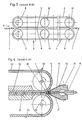
- the cable 1 is unwound from a drum (not shown) and transported in the X direction by the first conveyor 2.
- This first conveyor consists of a pair of belts 3, 4, the sections 5, 6 of which clamp the cable 1 between them.
- the belt drive is driven by the rollers 7, 8.
- the rollers 9, 10 form the deflection rollers, while the rollers 11, 12 only increase the contact pressure of the belt sections 5, 6 on the cable to be transported.
- the cable 1 is pushed into the channel 14, which is formed by a longitudinal groove in the bar 15 and by the spring plates 16, 17.
- a slide 18 formed from a thicker sheet metal strip engages in the longitudinal groove of the strip 15.
- This slide 18 pushes the cable 1 with a temporary resilient lifting of the edge regions 19 of the spring plates 16, 17 between the abutting sections 20, 21 of the belts 22, 23 forming the second conveyor 13.
- the belts 22, 23 are made of elastic material or at least have they have a soft elastic surface so that the cable 1 can be pushed between the superimposed belt sections 20, 21 so that the cable 1 is securely gripped by the conveyor 13. After the cable 1 is pressed into the second conveyor 24 by the slider 18, it is passed through the cutting device . 24, 25 cut to the desired length.
- FIG. 1 there is between the first conveyor 2 and the cutting device 24, 25, a guide tube 2B through which the cable 1 passes.
- This guide tube 28 is pivotally mounted about the axis 27 and is pivoted with the retraction of the slider 18 in the inlet of the belt sections 20, 21, as shown in Fig. 2, so that the cable 1 on the fixed knife 24 of the cutting device to the system is coming.
- the guide tube 28 is also pivoted back into the starting position, as shown in FIG. 1.
- the guide tube has the task of preventing the section la of the cable from being deformed out of the cable axis Z and being fed back into the axis Z after being cut to length so that the free end of this section 1 can be securely threaded into the channel 14.
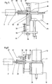
- the guide sleeve 28 which can be pivoted about the axis 27 is pressed by the tension spring 29 against a movable stop 30 which is rigidly coupled to the movable knife 25 and the slide 18.
- the tension spring 29 also ensures that the guide sleeve 28 bears securely against the stop 30 during the adjustment process of the stop 13 until the guide sleeve 28 comes into contact with the fixed stop 31. In this position of the guide sleeve, the cable 1 lies against the fixed knife 24 of the cutting device.
- the movable knife 15 When the movable knife 15 is advanced further, the cable 1 is cut to length. During this cutting process, the movable stop 30 lifts off the guide sleeve 28. During the cutting process, in which the cable 1 rests on the fixed knife 24, the guide sleeve 28 is not pivoted. When the slider 18 moves back, the guide sleeve 28 is pulled back into the drawn starting position against the force of the tension spring 29.
- the front pivotable end 31 of the guide sleeve 28 engages in a recess 32 of a tab-shaped part 26 coupled to the slide 18.
- the coupling of this part 26 to the slide 18 is non-positive, a compression spring 33 pressing a flange 34 rigidly coupled to the slide 18 against the edge 35 of a recess 36.
- This flange-shaped part 26 is formed at 38 as a ring knife. In this ring knife, the cable 1 is cut from the movable knife 25.
Landscapes
- Engineering & Computer Science (AREA)
- Manufacturing & Machinery (AREA)
- Forwarding And Storing Of Filamentary Material (AREA)
- Details Of Cutting Devices (AREA)
- Removal Of Insulation Or Armoring From Wires Or Cables (AREA)
Applications Claiming Priority (2)
| Application Number | Priority Date | Filing Date | Title |
|---|---|---|---|
| DE19843429054 DE3429054A1 (de) | 1984-08-07 | 1984-08-07 | Transportvorrichtung fuer einen kabelkonfektionierungsautomaten |
| DE3429054 | 1984-08-07 |
Publications (3)
| Publication Number | Publication Date |
|---|---|
| EP0171508A2 true EP0171508A2 (fr) | 1986-02-19 |
| EP0171508A3 EP0171508A3 (en) | 1989-04-12 |
| EP0171508B1 EP0171508B1 (fr) | 1991-09-11 |
Family
ID=6242521
Family Applications (1)
| Application Number | Title | Priority Date | Filing Date |
|---|---|---|---|
| EP19850104188 Expired - Lifetime EP0171508B1 (fr) | 1984-08-07 | 1985-04-05 | Dispositif de transport pour un automate de confection de câbles |
Country Status (3)
| Country | Link |
|---|---|
| EP (1) | EP0171508B1 (fr) |
| JP (1) | JPS6145864A (fr) |
| DE (1) | DE3429054A1 (fr) |
Cited By (3)
| Publication number | Priority date | Publication date | Assignee | Title |
|---|---|---|---|---|
| WO1992007399A1 (fr) * | 1990-10-10 | 1992-04-30 | Fraunhofer-Gesellschaft zur Förderung der angewandten Forschung e.V. | Dispositif d'amenee et de remplacement d'une pluralite de câbles |
| FR2691016A1 (fr) * | 1992-05-07 | 1993-11-12 | Stocko France | Machine de câblage, notamment destinée à équiper au moins l'une des extrémités d'un câble et/ou d'un tronçon, d'une pièce complémentaire. |
| CN114249171A (zh) * | 2021-12-13 | 2022-03-29 | 云南昆船烟草设备有限公司 | 一种纸箱包装带收带回收方法及装置 |
Family Cites Families (2)
| Publication number | Priority date | Publication date | Assignee | Title |
|---|---|---|---|---|
| US4502586A (en) * | 1982-03-31 | 1985-03-05 | Artos Engineering Company | Belt type conveyor for conveying wire segments |
| DE3416432C2 (de) * | 1984-05-04 | 1986-04-10 | Bernhard Dr.-Ing. 4782 Erwitte Jürgenhake | Transportvorrichtung für einen Kabelkonfektionierungsautomaten |
-
1984
- 1984-08-07 DE DE19843429054 patent/DE3429054A1/de active Granted
-
1985
- 1985-04-05 EP EP19850104188 patent/EP0171508B1/fr not_active Expired - Lifetime
- 1985-07-31 JP JP16784685A patent/JPS6145864A/ja active Pending
Cited By (4)
| Publication number | Priority date | Publication date | Assignee | Title |
|---|---|---|---|---|
| WO1992007399A1 (fr) * | 1990-10-10 | 1992-04-30 | Fraunhofer-Gesellschaft zur Förderung der angewandten Forschung e.V. | Dispositif d'amenee et de remplacement d'une pluralite de câbles |
| US5505398A (en) * | 1990-10-10 | 1996-04-09 | Fraunhofer Gesellschaft Zur Forderung Der Angewandten Forschung E.V. | Device for supplying and exchanging a plurality of cables |
| FR2691016A1 (fr) * | 1992-05-07 | 1993-11-12 | Stocko France | Machine de câblage, notamment destinée à équiper au moins l'une des extrémités d'un câble et/ou d'un tronçon, d'une pièce complémentaire. |
| CN114249171A (zh) * | 2021-12-13 | 2022-03-29 | 云南昆船烟草设备有限公司 | 一种纸箱包装带收带回收方法及装置 |
Also Published As
| Publication number | Publication date |
|---|---|
| DE3429054A1 (de) | 1986-02-20 |
| EP0171508B1 (fr) | 1991-09-11 |
| EP0171508A3 (en) | 1989-04-12 |
| DE3429054C2 (fr) | 1992-09-17 |
| JPS6145864A (ja) | 1986-03-05 |
Similar Documents
| Publication | Publication Date | Title |
|---|---|---|
| DE4211276C2 (de) | Haltevorrichtung zum Halten, Führen und Freigeben eines Fügeteils, wie z.B. einer Mutter | |
| EP0093318B1 (fr) | Machine à découenner | |
| DE2808617C2 (de) | Verfahren und Anlage zum Ausrichten von stapel- oder reihenförmigen Gruppen von Gegenständen | |
| DE19628170A1 (de) | Gerät zum Eintreiben von Befestigungselementen in harte Untergründe | |
| DE2750252C2 (de) | Kopiergerät | |
| EP3544131B1 (fr) | Machine de traitement de câbles dotée des éléments de guidage pouvant se déplacer et procédé d'insertion d'un câble dans une machine de traitement de câbles | |
| DE3416432C2 (de) | Transportvorrichtung für einen Kabelkonfektionierungsautomaten | |
| DE69306856T2 (de) | Binden von gelochten Bögen | |
| EP0399322A2 (fr) | Appareil de brochage | |
| DE69304614T2 (de) | Stangzufuhrvorrichtung für Stangenschubvorrichtungen an Werkzeugmaschinen | |
| DE3435250A1 (de) | Vorrichtung zum einsetzen von radial montierbaren federnden sicherungsringen in aeussere nuten von werkstuecken | |
| DE2360947B2 (de) | Vorrichtung zum Ausrichten einer Gruppe von Kuppelgliedern einer ReißverschluBkette | |
| DE2713333C3 (de) | Vorrichtung zur Führung des Papiers beim Papiertransport in Druckgeräten, insbesondere bei Fernschreibmaschinen | |
| EP0171508B1 (fr) | Dispositif de transport pour un automate de confection de câbles | |
| DE19548910C2 (de) | Blattzufuhrvorrichtung für einen Drucker zum Zuführen von Papier in einen Drucker und Drucker mit solcher Blattzufuhrvorrichtung | |
| DE2834915C2 (de) | Verfahren zum Erzeugen einer Reihe kuppelgliederfreier Lücken entlang einer durchgehenden Reißverschlußkette | |
| EP0626739B1 (fr) | Outil de pose de conducteurs électriques | |
| CH693577A5 (de) | Drahtmess- und Schneidevorrichtung und Verfahren zur Messung der Länge eines Drahtes. | |
| DE3108522C2 (de) | Verfahren und Vorrichtung zur Herstellung eines Drahtwendel-Gliederbandes aus vorgefertigten Drahtwendeln | |
| DE2308341C2 (de) | Maschine zum Abtrennen der Anschlußklemmen von einem Trägerstreifen und deren Einsetzen in eine Schaltungsplatte | |
| DE2625290C2 (de) | Vorrichtung zum Einführen wenigstens eines Garns in eine trichterförmig ausgebildete Eingangsöffnung einer pneumatischen Behandlungseinrichtung | |
| DE2952264C2 (fr) | ||
| DE3448002C2 (fr) | ||
| DE2548696A1 (de) | Automatisches bestueckungsgeraet | |
| DE2418558C3 (de) | Vorrichtung zum Festhalten eines Schiebers während des Einfädeins der Reißverschlußkette durch den Schieber |
Legal Events
| Date | Code | Title | Description |
|---|---|---|---|
| PUAI | Public reference made under article 153(3) epc to a published international application that has entered the european phase |
Free format text: ORIGINAL CODE: 0009012 |
|
| AK | Designated contracting states |
Designated state(s): FR GB IT NL SE |
|
| PUAL | Search report despatched |
Free format text: ORIGINAL CODE: 0009013 |
|
| AK | Designated contracting states |
Kind code of ref document: A3 Designated state(s): FR GB IT NL SE |
|
| 17P | Request for examination filed |
Effective date: 19891002 |
|
| 17Q | First examination report despatched |
Effective date: 19901112 |
|
| ITF | It: translation for a ep patent filed | ||
| GRAA | (expected) grant |
Free format text: ORIGINAL CODE: 0009210 |
|
| AK | Designated contracting states |
Kind code of ref document: B1 Designated state(s): FR GB IT NL SE |
|
| GBT | Gb: translation of ep patent filed (gb section 77(6)(a)/1977) | ||
| ET | Fr: translation filed | ||
| PLBE | No opposition filed within time limit |
Free format text: ORIGINAL CODE: 0009261 |
|
| STAA | Information on the status of an ep patent application or granted ep patent |
Free format text: STATUS: NO OPPOSITION FILED WITHIN TIME LIMIT |
|
| 26N | No opposition filed | ||
| ITF | It: translation for a ep patent filed | ||
| EAL | Se: european patent in force in sweden |
Ref document number: 85104188.9 |
|
| PGFP | Annual fee paid to national office [announced via postgrant information from national office to epo] |
Ref country code: SE Payment date: 19970212 Year of fee payment: 13 |
|
| PGFP | Annual fee paid to national office [announced via postgrant information from national office to epo] |
Ref country code: GB Payment date: 19970326 Year of fee payment: 13 |
|
| PGFP | Annual fee paid to national office [announced via postgrant information from national office to epo] |
Ref country code: NL Payment date: 19970430 Year of fee payment: 13 |
|
| PG25 | Lapsed in a contracting state [announced via postgrant information from national office to epo] |
Ref country code: GB Free format text: LAPSE BECAUSE OF NON-PAYMENT OF DUE FEES Effective date: 19980405 |
|
| PG25 | Lapsed in a contracting state [announced via postgrant information from national office to epo] |
Ref country code: SE Free format text: LAPSE BECAUSE OF NON-PAYMENT OF DUE FEES Effective date: 19980406 |
|
| PG25 | Lapsed in a contracting state [announced via postgrant information from national office to epo] |
Ref country code: NL Free format text: LAPSE BECAUSE OF NON-PAYMENT OF DUE FEES Effective date: 19981101 |
|
| GBPC | Gb: european patent ceased through non-payment of renewal fee |
Effective date: 19980405 |
|
| NLV4 | Nl: lapsed or anulled due to non-payment of the annual fee |
Effective date: 19981101 |
|
| EUG | Se: european patent has lapsed |
Ref document number: 85104188.9 |
|
| PGFP | Annual fee paid to national office [announced via postgrant information from national office to epo] |
Ref country code: FR Payment date: 19990217 Year of fee payment: 15 |
|
| PG25 | Lapsed in a contracting state [announced via postgrant information from national office to epo] |
Ref country code: FR Free format text: LAPSE BECAUSE OF NON-PAYMENT OF DUE FEES Effective date: 20001229 |
|
| REG | Reference to a national code |
Ref country code: FR Ref legal event code: ST |