EP0171649A2 - Filtre à plaques à profil réduit - Google Patents
Filtre à plaques à profil réduit Download PDFInfo
- Publication number
- EP0171649A2 EP0171649A2 EP85109045A EP85109045A EP0171649A2 EP 0171649 A2 EP0171649 A2 EP 0171649A2 EP 85109045 A EP85109045 A EP 85109045A EP 85109045 A EP85109045 A EP 85109045A EP 0171649 A2 EP0171649 A2 EP 0171649A2
- Authority
- EP
- European Patent Office
- Prior art keywords
- filter
- plate
- shaft
- arm
- filter plate
- Prior art date
- Legal status (The legal status is an assumption and is not a legal conclusion. Google has not performed a legal analysis and makes no representation as to the accuracy of the status listed.)
- Granted
Links
- 241000282472 Canis lupus familiaris Species 0.000 claims abstract description 31
- 230000008878 coupling Effects 0.000 claims description 8
- 238000010168 coupling process Methods 0.000 claims description 8
- 238000005859 coupling reaction Methods 0.000 claims description 8
- 238000001914 filtration Methods 0.000 claims description 7
- 230000000295 complement effect Effects 0.000 claims description 3
- 230000013011 mating Effects 0.000 claims description 3
- 239000007788 liquid Substances 0.000 description 22
- 230000000712 assembly Effects 0.000 description 9
- 238000000429 assembly Methods 0.000 description 9
- 230000008901 benefit Effects 0.000 description 5
- 238000004140 cleaning Methods 0.000 description 5
- 230000009471 action Effects 0.000 description 2
- 230000006835 compression Effects 0.000 description 2
- 238000007906 compression Methods 0.000 description 2
- 239000012530 fluid Substances 0.000 description 2
- 238000009434 installation Methods 0.000 description 2
- 238000004519 manufacturing process Methods 0.000 description 2
- 238000005555 metalworking Methods 0.000 description 2
- 238000010276 construction Methods 0.000 description 1
- 239000002826 coolant Substances 0.000 description 1
- 238000001816 cooling Methods 0.000 description 1
- 238000009826 distribution Methods 0.000 description 1
- 230000007246 mechanism Effects 0.000 description 1
- 238000000034 method Methods 0.000 description 1
- 230000004048 modification Effects 0.000 description 1
- 238000012986 modification Methods 0.000 description 1
- 230000008569 process Effects 0.000 description 1
- 238000007789 sealing Methods 0.000 description 1
- 238000003860 storage Methods 0.000 description 1
Images

Classifications
-
- B—PERFORMING OPERATIONS; TRANSPORTING
- B01—PHYSICAL OR CHEMICAL PROCESSES OR APPARATUS IN GENERAL
- B01D—SEPARATION
- B01D29/00—Filters with filtering elements stationary during filtration, e.g. pressure or suction filters, not covered by groups B01D24/00 - B01D27/00; Filtering elements therefor
- B01D29/09—Filters with filtering elements stationary during filtration, e.g. pressure or suction filters, not covered by groups B01D24/00 - B01D27/00; Filtering elements therefor with filtering bands, e.g. movable between filtering operations
- B01D29/096—Construction of filtering bands or supporting belts, e.g. devices for centering, mounting or sealing the filtering bands or the supporting belts
Definitions
- This invention is related to industrial plate filters of the type used to filter liquids, such as the liquid coolants used during metal working operations, and more particularly to a low profile plate filter using only a single pair of filter plates.
- U . S . Patent to Hirs 2,867,326 discloses filters of an older design which employ one or more pairs of stacked filter plates and various means for replacing contaminated filter media. It also discloses a gear drive mechanism for separating the filter plates or, alternatively, a pneumatic actuator mounted at the center of one of a pair of cooperating plates for raising and lowering the plate to permit the replacement of filter medium. By directly coupling the pneumatic actuator to one of the plates any pressure loss in the actuator, due to leaking seals, for example, can result in leakage of fluid from between the plates which, of course, is highly undesirable.
- the present invention is directed to a low profile plate filter which is simple in construction, fast in operation, capable of handling high flow rates and relatively inexpensive to build.
- the filter of the invention includes a lower filter plate mounted to a frame and an upper filter plate movably mounted above the lower filter plate.
- the upper filter plate is moved between an open position, in which the filter medium, e.g. filter paper can be pulled through a gap between the upper and lower filter plates, and a closed position, in which the region between the abutting filter plates is sealed thus capturing the filter paper between the filter plates.
- a fluid typically industrial cooling oil, is pumped through an inlet in the upper filter plate, passes through the filter paper and into the lower filter plate where it collects at and passes through an outlet for further use.
- the upper filter plate is supported by a number of eccentrically actuated tie rods pivotally mounted at their upper ends to opposite sides of the upper filter plate.
- the lower ends of the tie rods are pivotally mounted to and supported by a number of tie rod connectors.
- the tie rod connectors are mounted to the frame for eccentric movement about respective axes.
- Each tie rod connector is rigidly connected to an elongate crank arm so both the tie rod connectors and the crank arms rotate about their respective axis.
- the crank arms on each side of the filter are coupled together by connecting bars so that movement of one crank arm and tie rod connection therewith causes corresponding movement of the crank arms and tie rod connections to which it is connected.
- An actuator rotates the crank arms and tie rod connectors on both sides of the filter between first and second angular orientations. This is typically accomplished through an actuator arm keyed to an actuator shaft mounted to the frame below the lower filter plate; a crank arm and tie rod connection is secured at each end of the actuator shaft.
- the tie rod connection is preferably at, slightly past or near bottom dead center and the upper filter plate is closed against the lower filter plate.
- the actuator arm is at the second angular orientation, the tie rod connection is moved away from bottom dead center so to raise the upper filter plate.
- a safety locking assembly keeps the upper filter plate in position--that is fully closed or fully open.
- the safety locking assembly includes a locking arm mounted to the actuator shaft and positioned to engage upper and lower locking dogs when the upper filter plate is fully opened and fully closed.
- the locking dogs each have a locking recess for selective engagement of the end of the locking arm.
- the locking dogs are pivotally mounted to the frame and are biased towards the actuator axis to engage the locking arm. When the pneumatic actuator is energized, the locking dogs are pivoted away from the actuator axis to allow the free movement of the locking arm.
- the filter of the invention has a low profile and therefore can be transported assembled, which is not always possible with conventional filters.
- the low profile aspect of the filter also allows it to be mounted on top of liquid containers while still being serviceable from the ground without requiring special platforms, walkways, scaffolding and so forth.
- Another advantage of the filter made according to the invention is that it is substantially less expensive to manufacture than prior art filters having the same filter area, at least in part because it requires only a single filter paper extractor or, alternatively, the extractor can be eliminated and filter paper can be manually replaced to achieve even further cost savings.
- the cleaning cycle time is much shorter than that required by prior art filters operated with a motor and gear drive, for example, which raises and lowers the plates during filter paper replacement.
- the filter of the invention requires a cleaning cycle time on the order of seconds, while filters of the prior art commonly take minutes.
- the quick cleaning cycle time is enhanced by the use of a roll of filter paper and an automatic paper extractor which replaces the used filter paper between the upper and lower filter plates with clean filter paper.
- a cleaning cycle can be completed in as little as 1 minute.
- the short filter cleaning cycle makes it possible to operate the filter with smaller storage reservoirs for clean and contaminated liquids to sustain the continued operation of the metal working or other process which uses the liquid.
- high flow rates through the filter which may reach several hundred of gallons per minute, significant savings can thereby be achieved.
- Another advantage of the invention is that the liquid to be cleaned can be directed through inlets on the top of the upper filter plate and out of an outlet on the bottom of the lower filter plate. This achieves an even distribution of the liquid over the entire filter area and permits flow rates as high as 75 gals/min/square foot of filter area.
- tie rods are eccentrically driven, great mechanical advantage can be obtained during closing of the filter. That is, by adjusting the tie rods so that the filter is closed when the tie rod connection is at bottom dead center, a great amount of closing force can be exerted on the upper filter plate at the end of the closing stroke of the actuator. Doing so makes it unnecessary to subject many of the other components, such as the connecting bars, to correspondingly high forces.
- the filter of the present invention By employing tie-rods to move the filter plates relative to each other the need for a relatively expensive support frame is eliminated, thereby reducing the overall cost of the filter. Yet, the tie rod secures the opposite, typically elongate sides to each other at relatively short intervals so that leakage between the plates is prevented even when the internal liquid pressure is relatively high and/or the plates are of a large size, say up to 30 square feet or more.
- An additional advantage afforded by the filter of the present invention is that several filters can be arranged one behind the other to increase the filtration capacity. By serially positioning the filters in the direction of paper movement through them, a single paper extractor can be employed, thereby simplifying the entire installation and reducing installation and operating costs.
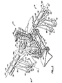
- a low profile filter 2 includes generally a frame 4 having a number of upstanding legs 6 to which a lower filter plate 8 is mounted by bolts 10.
- An upper filter plate 12 is movably mounted directly above the upper surface 14 of lower filter plate 8 through a raising and lowering assembly 16.
- a filter paper roll 18 is mounted to frame 4 at one end to allow filter paper 20 to be drawn through the gap 22 between upper and lower filter plates 12, 8 when filter 2 is in the open condition of Fig. 1.
- Filter paper 20 is pulled through gap 22 by a paper extractor 23 mounted to the end of frame 4 opposite paper roll 18.
- Raising and lowering assembly 16 includes five tie rods 24 mounted to each lateral side 26, 28 (see Fig. 2) of upper filter plate 12. The upper ends 29 of tie rods 24 are pivotally secured to upper filter plate 12 at pivot points 30. Raising and lowering assembly 16 also includes a number of crank member assemblies 32 connected to the lower end 34 of the tie rods 24 and a pair of crank member drive assemblies 36 operably coupled to the crank member assemblies as described below. The vertical movement of upper filter plate 12 is guided by a pair of guides 37 secured to opposite corners of upper and lower filter plates 12, 8.
- crank member drive assembly 36 drives crank member assemblies 32 which cause tie rods 24 to be raised and lowered in unison, thus raising and lowering upper filter plate 12.
- a liquid to be cleaned is pumped into upper filter plate 12 through inlets 38, passes through filter paper 20 captured between the outer edges 40, 42 of lower and upper filter plates 8, 12 respectively, into lower filter plate 8 and finally out outlet 44.
- filter paper 20 Once filter paper 20 has become sufficiently clogged, liquid flow into upper filter plate 12 is halted and the liquid within upper filter plate 12 is allowed to either drain through filter paper 20 or is removed through a quick blow down outlet 46 (Fig. 2).
- raising and lowering assembly 16 operates to raise upper filter plate 12 a short distance, for example l1 ⁇ 2 inches.
- Paper extractor 24 pulls the dirty filter paper 12 from between plates 8, 12 so that clean filter paper 20 from roll 18 takes its place.
- the amount of filter paper 20 pulled through filter 2 is monitored by a roller 48 which provides a series of pulses to paper extractor 23; paper extractor 23 stops pulling filter paper 20 through filter 2 when all the dirty filter paper has been removed from between filter plates 8, 12.
- assembly 16 lowers upper filter plate 12 onto lower filter plate 8 with force sufficient to seal edges 40, 42 from leaks. Filter 2 is now ready to begin filtering liquid again.
- crank arm 50 is mounted at its upper end 52 to the outer ends of five shafts 54.
- Shafts 54 are mounted to frame 4 beneath lower filter plate 8 by bearings 55.
- the left most shaft 54 of Fig. 1 is illustrated in Fig. 3 and is designated actuator shaft 54a for reasons which will be evident in light of the discussion below.
- shafts 54 and 54a are structurally the same.
- Arms 50 are keyed, welded or otherwise secured to shafts 54.
- a shaft extension 56 of shaft 54 extends through crank arms 50 and has a tie rod connection pin 58 welded to its periphery and extending parallel to the axis 60 of each shaft 54.
- Crank member assembly 32 in this preferred embodiment, thus includes crank arms 50, shaft extensions 56 and tie rod connection pins 58.
- Lower ends 34 of tie rods 24 are pivotally mounted to tie rod connection pins 58.
- Rotation of a shaft 54 causes pins 58 at either end to move about an axis 60 of shaft 54 and along arcs 61; this imparts an eccentric motion to the lower ends 34 of tie rods 24 thus causing tie rods 24 to move vertically to raise and lower upper filter plate 12.
- pins 58 are shown connected to shaft extensions 56, they could also be connected elsewhere, such as directly to crank arms 50 depending in part upon the size and placement of bearings 55.
- the pins 58 are rotated until they reach dead centei relative to pivot 30 on upper plate 12 to effectively lock the plates to each other in their closed position.
- the locking action can be enhanced by rotating the pins 58 slightly, i.e. a few degrees past dead center.
- the locking action is further increased when a relatively thick, resilient filter media is used, or when thin media is used, by including a seal ring, such as an O-ring 61 (Fig. 5) between the upper and lower plates 12, 8, respectively.
- the filter media, or the O-ring generate maximum compression forces when the pin 58 is at dead center and the forces are slightly less if there is overtravel.
- the torque required to rotate pin 58 past dead center must first increase before the liquid pressure between the plates can become effective to separate the plates.
- Tie rods 24 each include a turnbuckle section 62 so tie rods 24 are adjustable in length.
- the use of turnbuckle sections 62 will be described below.
- the outer ends 64 of the crank arms 50 along each lateral side 26, 28 are connected to one another through connecting bars 66. Thus movement of one crank arm 50 causes corresponding movement of each of the crank arms connected to one another by the same bar 66.
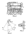
- Actuator shaft 54a includes a pair of actuator arms 68 keyed or otherwise affixed at their upper ends to shaft 54a. Arms 68 point in the same radial direction 69 as crank arms 50 secured to either end of shaft 54a (see also Fig. 4); this is why arms 68 are not visible in Fig. 1.
- the lower ends 70 of arms 68 are connected to the outer ends 72 of pneumatic rams 74.
- Rams 74 are powered by double acting pneumatic cylinders 76 (see Fig. 1) which supply the energy to rotate actuator arms 68 and actuator shaft 54a therewith, thus raising and lowering tie rods 24 and upper filter plate 12.
- Pneumatic rams 74 and pneumatic cylinders 76 are used to drive actuator arms 68 between a first position, shown in dashed lines in Fig. 3 and representing the open position of upper filter plate 12 of Figs. 1 and 2, and a second position, shown in solid lines in Fig. 3 and corresponding to filter plate 12 being in a closed position (not shown) with upper filter plate 12 seated on upper surface 14 of lower filter plate 8.
- This arc of travel 79 is approximately 66° and is illustrated schematically in Fig. 4.
- Crank member drive assembly 36 thus includes actuator shaft 54a, actuator arms 68, pneumatic actuators 78 and connecting bars 66.
- actuator shaft 54a In the preferred embodiment only a single shaft 54, actuator shaft 54a, is driven. However, two or more of shafts 54 may be driven by an actuator 78 if desired. Also some or all of shafts 54 need not have a crank member assembly 32 at each end, although the forces are better balanced when they do.
- a safety locking assembly 80 is used in conjunction with actuator shaft 54a to lock upper filter plate 12 in either its closed, sealed position or its open position.
- Assembly 80 includes broadly an elongate locking arm 82 fixed at its upper end to shaft 54a, upper and lower locking dogs 84, 86, and upper and lower spring biased actuators 88, 90 operably coupled to locking dogs 84, 86.
- An assembly 80 may be used in conjunction with other shafts 54 in addition to or in lieu of its use with shaft 54a.
- Upper and lower locking dogs 84, 86 are pivotally mounted to frame 4 at pivots 92, 94.
- the cases 89, 91 of upper and lower spring biased actuators 88, 90 are pivotally mounted to frame 4 at pivots 96, 98.
- the outer ends 100, 102 of the piston rods 104, 106 of actuators 88, 90 are pivotally connected to the outer ends 108, 110 of upper and lower locking dogs 84, 86.
- Actuators 88, 90 normally pull on outer ends 108, 110 to bias outer ends 108, 110 towards actuator axis 60. This allows the distal end 112 of locking arm 82 to be captured within locking recesses 114, 116 formed in locking dogs 84, 86 when upper filter plate 12 is in either its fully opened or fully closed position.
- recesses 114, 116 are positioned so that when actuator arm 68 is in its first position, shown in dashed lines in Fig. 3, distal end 112 of locking arm 82 is captured within locking recess 114; when actuator arm 68 is in its second, solid line position, distal end 112 is captured within recess 116.
- Lower locking dog 86 has a second locking recess 120 to accommodate a second final position of locking arm 82 when filter paper 20 is thicker than average.
- An upper limit stop 118 secured to frame 4, keeps locking arm 82 from moving past it in a counterclockwise direction (as seen in Figs. 1 and 3) thus limiting how far upper filter plate 12 opens.
- a lower limit stop 122 also secured to frame 4, limits the pivotal movement of locking arm 82 in a clockwise direction as shown in Fig. 3.
- Some filter paper is relatively thick, sometimes up to 3/16 inch thick, but does not compress as much when dry as when wet. To allow for this extra compression during use, stop 122 is preferably positioned so that there is a small ⁇ gap 128, for example ; inch, between lower limit stop 122 and locking arm 82 when arm 82 is at bottom dead center.
- both upper and lower spring biased actuators 88, 90 become active so that their respective piston rods 104, 106 extend to pivot locking dogs 84, 86 away from actuator axis 60.
- spring biased actuators 88, 90 are deenergized causing their piston rods 106, 108 to be withdrawn thus pulling outer ends 108, 110 of upper and lower locking dogs 84, 86 towards actuator axis 60 to lock arm 82 in place.
- center line 124 of locking arm 182 is radially aligned with a line 126 connecting actuator axis 60 and the center of tie rod connection pin 58.
- axis 124 is also vertical. This alignment is illustrated schematically in Fig. 4.
- filter paper 20 from roll 18 is directed through gap 22 between upper and lower filter plates 12, 8 and threaded through paper extractor 24.
- Assembly 16 is actuated to lower upper filter plate 12 onto lower filter plate 8 thereby capturing the peripherial edges of filter paper 20 between outer edges 40, 42 of lower and upper filter plates 8, 12. This is accomplished by actuating pneumatic cylinders 76 causing actuator arms 68 to rotate from their first (dashed line) positions in Fig. 3 to their second (solid line) positions.
- actuator shaft 54a includes a crank arm 50 at either end and since all crank arms 50 on either side of filter 2 are coupled together by connecting bars 66, rotation of actuator shaft 54a causes all other actuator shafts 54, through their respective crank arms 50, to rotate as well.
- Tie rod connection pins 58 all rotate about their associated axes 60 until pins 58 are at about bottom dead center and their respected axes 126 are generally vertical.
- actuators 78 are operated to pull actuator arms 68 from their second, solid line positions of Fig. 3, back to their first broken line positions of Fig. 3.
- spring biased actuators 88, 90 are energized thus pivoting upper and lower locking dogs 84, 86 away from actuator axis 60a to allow locking arm 82 to swing freely between its second and first positions.
- Rotation of actuator arms 68 causes actuator shaft 54a to rotate thus driving tie rod connection pins 58 attached at either end in a counterclockwise direction to raise tie rods 24 and thus raise upper filter plate 12.
- filter paper extractors may be used in lieu of extractor 24.
- the filter media used need not be from a roll of filter paper, and need not even be filter paper.
- Filter plates 8, 12 may be of other shapes, say of a square shape; however rectangular filter plates work well for relatively large filter areas, particularly when using continuous feed filter paper.
- the invention may be summarized as follows:
Landscapes
- Chemical & Material Sciences (AREA)
- Chemical Kinetics & Catalysis (AREA)
- Filtration Of Liquid (AREA)
Applications Claiming Priority (2)
| Application Number | Priority Date | Filing Date | Title |
|---|---|---|---|
| US06/632,505 US4582602A (en) | 1984-07-19 | 1984-07-19 | Low profile plate filter |
| US632505 | 1984-07-19 |
Publications (3)
| Publication Number | Publication Date |
|---|---|
| EP0171649A2 true EP0171649A2 (fr) | 1986-02-19 |
| EP0171649A3 EP0171649A3 (en) | 1988-02-17 |
| EP0171649B1 EP0171649B1 (fr) | 1991-06-12 |
Family
ID=24535778
Family Applications (1)
| Application Number | Title | Priority Date | Filing Date |
|---|---|---|---|
| EP85109045A Expired EP0171649B1 (fr) | 1984-07-19 | 1985-07-19 | Filtre à plaques à profil réduit |
Country Status (5)
| Country | Link |
|---|---|
| US (1) | US4582602A (fr) |
| EP (1) | EP0171649B1 (fr) |
| JP (1) | JPS6135813A (fr) |
| CA (1) | CA1259032A (fr) |
| DE (1) | DE3583190D1 (fr) |
Cited By (1)
| Publication number | Priority date | Publication date | Assignee | Title |
|---|---|---|---|---|
| EP0706812A1 (fr) * | 1994-10-11 | 1996-04-17 | Astec Environmental Systems Limited | Montage de filtres |
Families Citing this family (1)
| Publication number | Priority date | Publication date | Assignee | Title |
|---|---|---|---|---|
| US6811032B2 (en) * | 2003-01-16 | 2004-11-02 | Varco I/P, Inc. | Shaker roll screen |
Family Cites Families (16)
| Publication number | Priority date | Publication date | Assignee | Title |
|---|---|---|---|---|
| US2867326A (en) * | 1955-09-27 | 1959-01-06 | Hirs Gene | Filter apparatus |
| US2867325A (en) * | 1955-09-27 | 1959-01-06 | Hirs Gene | Filter apparatus |
| US2867324A (en) * | 1956-03-12 | 1959-01-06 | Hirs Gene | Filter apparatus |
| US2918862A (en) * | 1956-10-30 | 1959-12-29 | Int Paper Co | Press unloading apparatus |
| US3237463A (en) * | 1963-04-23 | 1966-03-01 | Sta Co Corp De | Double acting plunger clamp |
| US3305094A (en) * | 1964-07-08 | 1967-02-21 | Barnes Drill Co | Vaccum filter |
| US3608734A (en) * | 1968-07-31 | 1971-09-28 | John R Schneider | Liquid filtering apparatus |
| US4102788A (en) * | 1973-01-16 | 1978-07-25 | English Clays Lovering Pochin & Company Limited | Plate filter presses |
| FR2216106B1 (fr) * | 1973-02-07 | 1976-05-14 | Secim | |
| DE2421781C2 (de) * | 1974-05-06 | 1984-06-14 | Eberhard Hoesch & Söhne, 5160 Düren | Etagendruckfilter mit horizontal ausgerichteten Filterplatten |
| US4008158A (en) * | 1974-10-31 | 1977-02-15 | Envirotech Corporation | Dewatering machine |
| GB1573099A (en) * | 1975-12-30 | 1980-08-13 | Newalls Insulation Co Ltd | Apparatus for the manufacture of insulating products |
| JPS5469875A (en) * | 1977-11-15 | 1979-06-05 | Nippon Kokan Kk <Nkk> | Dewatering apparatus |
| JPS5946646B2 (ja) * | 1980-09-19 | 1984-11-14 | 株式会社栗田機械製作所 | フイルタプレスの「ろ」材吊持装置 |
| US4329228A (en) * | 1981-02-23 | 1982-05-11 | J. R. Schneider Co., Inc. | Filter plate for horizontal plate filter |
| US4362617A (en) * | 1981-05-06 | 1982-12-07 | Micronic Filtration Inc. | Liquid filtering apparatus |
-
1984
- 1984-07-19 US US06/632,505 patent/US4582602A/en not_active Expired - Lifetime
-
1985
- 1985-07-12 CA CA000486776A patent/CA1259032A/fr not_active Expired
- 1985-07-18 JP JP15921785A patent/JPS6135813A/ja active Granted
- 1985-07-19 EP EP85109045A patent/EP0171649B1/fr not_active Expired
- 1985-07-19 DE DE8585109045T patent/DE3583190D1/de not_active Expired - Lifetime
Cited By (2)
| Publication number | Priority date | Publication date | Assignee | Title |
|---|---|---|---|---|
| EP0706812A1 (fr) * | 1994-10-11 | 1996-04-17 | Astec Environmental Systems Limited | Montage de filtres |
| GB2295333B (en) * | 1994-10-11 | 1998-04-08 | Astec Environmental Sys Ltd | Filter mounting |
Also Published As
| Publication number | Publication date |
|---|---|
| EP0171649A3 (en) | 1988-02-17 |
| JPH0457365B2 (fr) | 1992-09-11 |
| DE3583190D1 (de) | 1991-07-18 |
| US4582602A (en) | 1986-04-15 |
| EP0171649B1 (fr) | 1991-06-12 |
| JPS6135813A (ja) | 1986-02-20 |
| CA1259032A (fr) | 1989-09-05 |
Similar Documents
| Publication | Publication Date | Title |
|---|---|---|
| AU2019252265B2 (en) | Discharge filter plate assembly for filter press | |
| CA2133757C (fr) | Filtre et methode | |
| DE69019901T2 (de) | System zum Reinigen eines Druckzylinders. | |
| CA1074709A (fr) | Filtre a deux semi-coquilles du type a auto-entretien | |
| CN115282655A (zh) | 压滤机悬挂式进料器 | |
| US4582602A (en) | Low profile plate filter | |
| CN2510153Y (zh) | 多功能过滤干燥机 | |
| CN111379707B (zh) | 一种防堵塞污水泵 | |
| CN206660687U (zh) | 一种压滤装置 | |
| US5277109A (en) | Sanitary liquid/solid separator | |
| CN216677128U (zh) | 一种框板压滤机 | |
| CN116850658A (zh) | 一种滤板刮料机构及压滤机 | |
| CN224086122U (zh) | 一种全自动滤布旋转卸饼水洗压滤机 | |
| CN117244299B (zh) | 一种中央纯水智慧运维设备 | |
| CN223570163U (zh) | 一种切削液过滤回收装置 | |
| CN220760558U (zh) | 一种冷轧机轧制油回用系统 | |
| CN111762990A (zh) | 一种污泥再利用处理自动化输送系统 | |
| CN222816611U (zh) | 一种自动控制反渗透清洗系统 | |
| CA3095750C (fr) | Ensemble plaque de filtre a decharge pour filtre presse | |
| CN221109183U (zh) | 一种滤饼易取出的水洗装置 | |
| CN216629806U (zh) | 一种新型板框压滤机的翻板机构 | |
| CN116173583B (zh) | 一种聚氨酯乳液的制备装置及制备工艺 | |
| CN215352254U (zh) | 一种可拆卸式磨削液循环装置 | |
| CN215588640U (zh) | 一种基于高强度不锈钢法兰加工的磨削装置 | |
| DE20019721U1 (de) | Filtereinrichtung |
Legal Events
| Date | Code | Title | Description |
|---|---|---|---|
| PUAI | Public reference made under article 153(3) epc to a published international application that has entered the european phase |
Free format text: ORIGINAL CODE: 0009012 |
|
| AK | Designated contracting states |
Designated state(s): DE FR GB IT |
|
| 17P | Request for examination filed |
Effective date: 19860821 |
|
| PUAL | Search report despatched |
Free format text: ORIGINAL CODE: 0009013 |
|
| AK | Designated contracting states |
Kind code of ref document: A3 Designated state(s): DE FR GB IT |
|
| 17Q | First examination report despatched |
Effective date: 19890306 |
|
| ITF | It: translation for a ep patent filed | ||
| GRAA | (expected) grant |
Free format text: ORIGINAL CODE: 0009210 |
|
| AK | Designated contracting states |
Kind code of ref document: B1 Designated state(s): DE FR GB IT |
|
| REF | Corresponds to: |
Ref document number: 3583190 Country of ref document: DE Date of ref document: 19910718 |
|
| ET | Fr: translation filed | ||
| PLBE | No opposition filed within time limit |
Free format text: ORIGINAL CODE: 0009261 |
|
| STAA | Information on the status of an ep patent application or granted ep patent |
Free format text: STATUS: NO OPPOSITION FILED WITHIN TIME LIMIT |
|
| 26N | No opposition filed | ||
| PGFP | Annual fee paid to national office [announced via postgrant information from national office to epo] |
Ref country code: GB Payment date: 20000703 Year of fee payment: 16 Ref country code: DE Payment date: 20000703 Year of fee payment: 16 |
|
| PGFP | Annual fee paid to national office [announced via postgrant information from national office to epo] |
Ref country code: FR Payment date: 20000706 Year of fee payment: 16 |
|
| PG25 | Lapsed in a contracting state [announced via postgrant information from national office to epo] |
Ref country code: GB Free format text: LAPSE BECAUSE OF NON-PAYMENT OF DUE FEES Effective date: 20010719 |
|
| GBPC | Gb: european patent ceased through non-payment of renewal fee |
Effective date: 20010719 |
|
| PG25 | Lapsed in a contracting state [announced via postgrant information from national office to epo] |
Ref country code: FR Free format text: LAPSE BECAUSE OF NON-PAYMENT OF DUE FEES Effective date: 20020329 |
|
| PG25 | Lapsed in a contracting state [announced via postgrant information from national office to epo] |
Ref country code: DE Free format text: LAPSE BECAUSE OF NON-PAYMENT OF DUE FEES Effective date: 20020501 |
|
| REG | Reference to a national code |
Ref country code: FR Ref legal event code: ST |