EP0172033B1 - Brennkraftmaschine - Google Patents
Brennkraftmaschine Download PDFInfo
- Publication number
- EP0172033B1 EP0172033B1 EP85305824A EP85305824A EP0172033B1 EP 0172033 B1 EP0172033 B1 EP 0172033B1 EP 85305824 A EP85305824 A EP 85305824A EP 85305824 A EP85305824 A EP 85305824A EP 0172033 B1 EP0172033 B1 EP 0172033B1
- Authority
- EP
- European Patent Office
- Prior art keywords
- vane
- engine
- combustion
- row
- chamber
- Prior art date
- Legal status (The legal status is an assumption and is not a legal conclusion. Google has not performed a legal analysis and makes no representation as to the accuracy of the status listed.)
- Expired - Lifetime
Links
- 238000002485 combustion reaction Methods 0.000 title claims abstract description 20
- 239000000567 combustion gas Substances 0.000 claims description 14
- 239000000203 mixture Substances 0.000 abstract description 3
- 239000007789 gas Substances 0.000 description 14
- 238000012986 modification Methods 0.000 description 6
- 230000004048 modification Effects 0.000 description 6
- 230000006835 compression Effects 0.000 description 5
- 238000007906 compression Methods 0.000 description 5
- 239000000446 fuel Substances 0.000 description 5
- 238000010586 diagram Methods 0.000 description 4
- 239000003570 air Substances 0.000 description 1
- 239000007787 solid Substances 0.000 description 1
Images




Classifications
-
- F—MECHANICAL ENGINEERING; LIGHTING; HEATING; WEAPONS; BLASTING
- F01—MACHINES OR ENGINES IN GENERAL; ENGINE PLANTS IN GENERAL; STEAM ENGINES
- F01C—ROTARY-PISTON OR OSCILLATING-PISTON MACHINES OR ENGINES
- F01C21/00—Component parts, details or accessories not provided for in groups F01C1/00 - F01C20/00
- F01C21/18—Arrangements for admission or discharge of the working fluid, e.g. constructional features of the inlet or outlet
-
- F—MECHANICAL ENGINEERING; LIGHTING; HEATING; WEAPONS; BLASTING
- F01—MACHINES OR ENGINES IN GENERAL; ENGINE PLANTS IN GENERAL; STEAM ENGINES
- F01C—ROTARY-PISTON OR OSCILLATING-PISTON MACHINES OR ENGINES
- F01C1/00—Rotary-piston machines or engines
- F01C1/30—Rotary-piston machines or engines having the characteristics covered by two or more groups F01C1/02, F01C1/08, F01C1/22, F01C1/24 or having the characteristics covered by one of these groups together with some other type of movement between co-operating members
- F01C1/34—Rotary-piston machines or engines having the characteristics covered by two or more groups F01C1/02, F01C1/08, F01C1/22, F01C1/24 or having the characteristics covered by one of these groups together with some other type of movement between co-operating members having the movement defined in group F01C1/08 or F01C1/22 and relative reciprocation between the co-operating members
- F01C1/344—Rotary-piston machines or engines having the characteristics covered by two or more groups F01C1/02, F01C1/08, F01C1/22, F01C1/24 or having the characteristics covered by one of these groups together with some other type of movement between co-operating members having the movement defined in group F01C1/08 or F01C1/22 and relative reciprocation between the co-operating members with vanes reciprocating with respect to the inner member
- F01C1/3446—Rotary-piston machines or engines having the characteristics covered by two or more groups F01C1/02, F01C1/08, F01C1/22, F01C1/24 or having the characteristics covered by one of these groups together with some other type of movement between co-operating members having the movement defined in group F01C1/08 or F01C1/22 and relative reciprocation between the co-operating members with vanes reciprocating with respect to the inner member the inner and outer member being in contact along more than one line or surface
-
- F—MECHANICAL ENGINEERING; LIGHTING; HEATING; WEAPONS; BLASTING
- F01—MACHINES OR ENGINES IN GENERAL; ENGINE PLANTS IN GENERAL; STEAM ENGINES
- F01C—ROTARY-PISTON OR OSCILLATING-PISTON MACHINES OR ENGINES
- F01C1/00—Rotary-piston machines or engines
- F01C1/30—Rotary-piston machines or engines having the characteristics covered by two or more groups F01C1/02, F01C1/08, F01C1/22, F01C1/24 or having the characteristics covered by one of these groups together with some other type of movement between co-operating members
- F01C1/34—Rotary-piston machines or engines having the characteristics covered by two or more groups F01C1/02, F01C1/08, F01C1/22, F01C1/24 or having the characteristics covered by one of these groups together with some other type of movement between co-operating members having the movement defined in group F01C1/08 or F01C1/22 and relative reciprocation between the co-operating members
- F01C1/356—Rotary-piston machines or engines having the characteristics covered by two or more groups F01C1/02, F01C1/08, F01C1/22, F01C1/24 or having the characteristics covered by one of these groups together with some other type of movement between co-operating members having the movement defined in group F01C1/08 or F01C1/22 and relative reciprocation between the co-operating members with vanes reciprocating with respect to the outer member
- F01C1/3566—Rotary-piston machines or engines having the characteristics covered by two or more groups F01C1/02, F01C1/08, F01C1/22, F01C1/24 or having the characteristics covered by one of these groups together with some other type of movement between co-operating members having the movement defined in group F01C1/08 or F01C1/22 and relative reciprocation between the co-operating members with vanes reciprocating with respect to the outer member the inner and outer member being in contact along more than one line or surface
-
- F—MECHANICAL ENGINEERING; LIGHTING; HEATING; WEAPONS; BLASTING
- F01—MACHINES OR ENGINES IN GENERAL; ENGINE PLANTS IN GENERAL; STEAM ENGINES
- F01C—ROTARY-PISTON OR OSCILLATING-PISTON MACHINES OR ENGINES
- F01C1/00—Rotary-piston machines or engines
- F01C1/30—Rotary-piston machines or engines having the characteristics covered by two or more groups F01C1/02, F01C1/08, F01C1/22, F01C1/24 or having the characteristics covered by one of these groups together with some other type of movement between co-operating members
- F01C1/34—Rotary-piston machines or engines having the characteristics covered by two or more groups F01C1/02, F01C1/08, F01C1/22, F01C1/24 or having the characteristics covered by one of these groups together with some other type of movement between co-operating members having the movement defined in group F01C1/08 or F01C1/22 and relative reciprocation between the co-operating members
- F01C1/356—Rotary-piston machines or engines having the characteristics covered by two or more groups F01C1/02, F01C1/08, F01C1/22, F01C1/24 or having the characteristics covered by one of these groups together with some other type of movement between co-operating members having the movement defined in group F01C1/08 or F01C1/22 and relative reciprocation between the co-operating members with vanes reciprocating with respect to the outer member
- F01C1/3568—Rotary-piston machines or engines having the characteristics covered by two or more groups F01C1/02, F01C1/08, F01C1/22, F01C1/24 or having the characteristics covered by one of these groups together with some other type of movement between co-operating members having the movement defined in group F01C1/08 or F01C1/22 and relative reciprocation between the co-operating members with vanes reciprocating with respect to the outer member with axially movable vanes
-
- F—MECHANICAL ENGINEERING; LIGHTING; HEATING; WEAPONS; BLASTING
- F01—MACHINES OR ENGINES IN GENERAL; ENGINE PLANTS IN GENERAL; STEAM ENGINES
- F01C—ROTARY-PISTON OR OSCILLATING-PISTON MACHINES OR ENGINES
- F01C11/00—Combinations of two or more machines or engines, each being of rotary-piston or oscillating-piston type
- F01C11/002—Combinations of two or more machines or engines, each being of rotary-piston or oscillating-piston type of similar working principle
- F01C11/004—Combinations of two or more machines or engines, each being of rotary-piston or oscillating-piston type of similar working principle and of complementary function, e.g. internal combustion engine with supercharger
-
- F—MECHANICAL ENGINEERING; LIGHTING; HEATING; WEAPONS; BLASTING
- F01—MACHINES OR ENGINES IN GENERAL; ENGINE PLANTS IN GENERAL; STEAM ENGINES
- F01C—ROTARY-PISTON OR OSCILLATING-PISTON MACHINES OR ENGINES
- F01C21/00—Component parts, details or accessories not provided for in groups F01C1/00 - F01C20/00
- F01C21/06—Heating; Cooling; Heat insulation
-
- F—MECHANICAL ENGINEERING; LIGHTING; HEATING; WEAPONS; BLASTING
- F01—MACHINES OR ENGINES IN GENERAL; ENGINE PLANTS IN GENERAL; STEAM ENGINES
- F01C—ROTARY-PISTON OR OSCILLATING-PISTON MACHINES OR ENGINES
- F01C21/00—Component parts, details or accessories not provided for in groups F01C1/00 - F01C20/00
- F01C21/08—Rotary pistons
- F01C21/0809—Construction of vanes or vane holders
-
- F—MECHANICAL ENGINEERING; LIGHTING; HEATING; WEAPONS; BLASTING
- F02—COMBUSTION ENGINES; HOT-GAS OR COMBUSTION-PRODUCT ENGINE PLANTS
- F02B—INTERNAL-COMBUSTION PISTON ENGINES; COMBUSTION ENGINES IN GENERAL
- F02B53/00—Internal-combustion aspects of rotary-piston or oscillating-piston engines
-
- F—MECHANICAL ENGINEERING; LIGHTING; HEATING; WEAPONS; BLASTING
- F02—COMBUSTION ENGINES; HOT-GAS OR COMBUSTION-PRODUCT ENGINE PLANTS
- F02B—INTERNAL-COMBUSTION PISTON ENGINES; COMBUSTION ENGINES IN GENERAL
- F02B55/00—Internal-combustion aspects of rotary pistons; Outer members for co-operation with rotary pistons
- F02B55/08—Outer members for co-operation with rotary pistons; Casings
- F02B55/10—Cooling thereof
- F02B55/12—Cooling thereof by air or other gas
-
- F—MECHANICAL ENGINEERING; LIGHTING; HEATING; WEAPONS; BLASTING
- F02—COMBUSTION ENGINES; HOT-GAS OR COMBUSTION-PRODUCT ENGINE PLANTS
- F02B—INTERNAL-COMBUSTION PISTON ENGINES; COMBUSTION ENGINES IN GENERAL
- F02B75/00—Other engines
- F02B75/02—Engines characterised by their cycles, e.g. six-stroke
- F02B2075/022—Engines characterised by their cycles, e.g. six-stroke having less than six strokes per cycle
- F02B2075/027—Engines characterised by their cycles, e.g. six-stroke having less than six strokes per cycle four
-
- Y—GENERAL TAGGING OF NEW TECHNOLOGICAL DEVELOPMENTS; GENERAL TAGGING OF CROSS-SECTIONAL TECHNOLOGIES SPANNING OVER SEVERAL SECTIONS OF THE IPC; TECHNICAL SUBJECTS COVERED BY FORMER USPC CROSS-REFERENCE ART COLLECTIONS [XRACs] AND DIGESTS
- Y02—TECHNOLOGIES OR APPLICATIONS FOR MITIGATION OR ADAPTATION AGAINST CLIMATE CHANGE
- Y02T—CLIMATE CHANGE MITIGATION TECHNOLOGIES RELATED TO TRANSPORTATION
- Y02T10/00—Road transport of goods or passengers
- Y02T10/10—Internal combustion engine [ICE] based vehicles
- Y02T10/12—Improving ICE efficiencies
Definitions
- the present invention relates to internal combustion engines and, in particular, to continuous linear internal combustion engines applicable, for example, to mono rail systems.
- a continuous linear internal combustion engine is described, inter alia, in US Patent 4,127,094.
- This engine has a piston traversing a tubular chamber sealed by gate valves, and the piston has an internal chamber into which fuel is supplied.
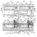
- Figures 9 and 10 are again a plan and a sectional elevation of a further modified engine.
- the engine comprises a track formed with two rows of recesses.
- the first row of recesses consists of alternately shallower recesses 104, forming intake chambers in which combustion gas, i.e. a petrol- air mixture in the case of a petrol engine, and air if the engine is a diesel type engine, is taken in and compressed.
- Deeper chambers 105 form combustion chambers in which fuel is burned to provide power for the engine.
- the chamber 104 has an extension 104' which communicates with a groove in the moving portion of the engine through which the supply of combustion gas is received.
- the combustion chamber 105 has two extensions 105', one of which communicates with a groove 111 in the moving portion of the engine through which the burnt combustion gases are exhausted, and the other, which is shorter, communicates with a transfer port 1060 in the moving portion of the engine.
- Vanes 106 which are mounted in the moving portion of the engine and are spring loaded, traverse these chambers in operation, and act as pistons for drawing in gas or air, and fuel nozzles or ignition devices 108, according to the type of engine, are also mounted in the moving part.
- the trackway also has a second row of recesses similar to the intake recesses 104 of the first row, and having extensions 104' which will communicate with the transfer port 1060 in the moving part as it passes.
- a spring-loaded vane 1040 in the moving part acts as a piston traversing this chamber, and an inlet for combustion gas 110' is provided just to the rear of this vane.
- the vane 106 has an internal high pressure chamber with an inlet 101 provided with a non-return valve near its tip, and an outlet 103 positioned at a distance from the tip such that it is exposed while the vane is traversing the combustion chamber, but is covered, and therefore sealed, by the body of the moving portion of the engine while the vane is traversing the relatively shallower intake chamber.
- Figure 2 also shows the mounting 125 of a vane.
- the vane 1040 which is indicated in dotted outline in the section of Figure 2 does not have this structure, but is a simple solid vane, similarly spring-loaded.
- Figures 3(a) to 3(e) are diagrams showing successive stages in the operation of the engine. The diagrams are taken from a viewpoint on the moving portion of the engine, so that the trackway with its recesses is moving relatively to the right in the views shown in the figures.
- the first of the recesses in the first or upper row is an intake chamber, with the vane near the end of the compression stroke. At the left hand end the combustion gas is being compressed into the high pressure chamber within the vane, whereas at the right hand end combustion gas is still being drawn in from the inlet groove.
- the second recess is a combustion chamber approaching the end of its power stroke, and with residual gas from the previous power stroke still being exhausted into the exhaust passage from the region to the left of the vane. In the lower row of recesses, combustion gas is being compressed.
- Figure 3(b) is a similar view at a slightly later moment.
- a vane In the first row of recesses, a vane is about to enter each intake and compression chamber. In the second row gas in the recesses is becoming highly compressed.
- Figure 3(c) shows the commencement of the next power stroke.
- Gas held under high pressure within the high pressure chamber of the vane is released as the vane enters the deeper chamber and the spark plug (or in the case of a diesel engine, the fuel jet) causes the fuel to ignite.
- the spark plug or in the case of a diesel engine, the fuel jet
- highly compressed gas is now being transferred to the transfer port, while combustion gas in the intake chambers of the first row is becoming compressed.
- Figure 3(d) shows the situation a fraction later, during the power stroke. Compressed gas from the transfer port has been added to the burning gas in the combustion chamber of the upper row, making further power available for the power stoke. Exhaust gas to the left of the vane from the previous power stroke is being exhausted into the exhaust groove.
- Figure 3(e) shows a later stage with the power stroke continuing, and gas being compressed in the intake chambers of the upper and the lower row. The cycle then repeats.
- Figures 4 and 5 show a modification of the engine in which the inlet and exhaust arrangements are very much simplified.
- inlet passages 110' and exhaust passages 111' are drilled into the intake and combustion chambers of the trackway so that the grooves and projections required for inlet and exhaust in the arrangement of Figures 1 and 2 are avoided.
- the only passage required in the moving portion of the engine is the transfer port 1060.
- the operation of this embodiment is identical to that described with reference to Figures 3(a) to 3(e).
- Figures 6 and 7 show a further modification of the arrangement of Figures 1 and 2.
- the chambers of the second row do not communicate with the transfer port 1060, but instead the vane that traverses these chambers is provided with an internal passageway 1020 communicating with the transfer port 1010.
- the first of the recesses in the first or upper row is an intake chamber and the vane is near the end of its compression stroke.
- the combustion gas is being compressed into the high pressure chamber within the vane, whereas at the right hand end combustion gas is still being drawn in from the inlet groove.
- the second recess in this row is a combustion chamber approaching the end of its power stroke, with residual gas from the previous power stroke still being exhausted into the exhaust passage from the region to the left of the vane.
- combustion gas is being compressed to the left of the vane, and is passing under pressure, through the passage within the vane into the transfer port.
- Figure 8(b) is taken at a slightly later moment and shows a vane about to enter each intake and compression chamber in the first row. In the second row the compression of gas into the transfer port is continuing.
- Figure 8(c) shows the beginning of the next power stroke and in Figure 8(d) a moment later, the very highly compressed gas in the transfer port is transferred to the burning mixture making further power available for this power stroke. At the same time burnt gas from the previous power stroke on the left hand side of the vane is being exhausted into the exhaust groove.
- Figure 8(e) shows a slightly later stage in which the power stroke is continuing and fresh gas is being compressed in the intake chambers of both the upper and the lower rows.
- Figures 9 and 10 show a further modification of the arrangement of Figures 6-8.
- the inlet and exhaust grooves are replaced by inlet and exhaust passages 110' and 111' drilled into the intake and combustion chambers of the trackway.
- the operation of this embodiment is identical to that described with reference to Figures 8(a) to 8(e).
Landscapes
- Engineering & Computer Science (AREA)
- Mechanical Engineering (AREA)
- General Engineering & Computer Science (AREA)
- Chemical & Material Sciences (AREA)
- Combustion & Propulsion (AREA)
- Combustion Methods Of Internal-Combustion Engines (AREA)
- Valve Device For Special Equipments (AREA)
- Output Control And Ontrol Of Special Type Engine (AREA)
- Valve-Gear Or Valve Arrangements (AREA)
- Transition And Organic Metals Composition Catalysts For Addition Polymerization (AREA)
- Mechanical Treatment Of Semiconductor (AREA)
- Internal Circuitry In Semiconductor Integrated Circuit Devices (AREA)
Claims (1)
- Eine kontinuierliche, lineare Kraftmaschine für innere Verbrennung mit einer Mehrzahl von Einlaßkammern (104), einer Mehrzahl von Brennkammern (105) und einem die Einlaß- und Brennkammern durchquerenden Kolben, der eine Hochdruckkammer (102) enthält und einen Einlaß (101), durch den hindurch Brenngas in die Hochdruckkammer hinein verdichtet wird, sowie einen aus der Hochdruckkammer heraus führenden Auslaß (103) besitzt, dadurch gekennzeichnet, daß die Maschine eine Laufbahn besitzt, die mit zwei parallelen Reihen von Vertiefungen versehen ist, wobei die Vertiefungen einer ersten Reihe abwechselnd eine geringere und eine größere Tiefe besitzen, um die genannten Einlaßkammern bzw. die genannten Brennkammern zu bilden, daß der genannten Kolben, der für die erste Reihe vorgesehen ist, ein federbelastetes Blatt (106) aufweist, innerhalb dem die Hochdruckkammer (102) ein an ihrem Einlaß (101) befindliches Rückschlagventil aufweist und an dem ein Auslaß (103) so gelegen ist, daß er freigegeben ist, während sich das Blatt innerhalb einer Brennkammer befindet, und er während des ganzen Zeitraums verdeckt ist, in dem das Blatt eine Einlaßkammer durchquert, daß ein weiteres federbelastetes Blatt (1040) vorgesehen ist, um Brenngas in den Vertiefungen der zweiten Reihe zu verdichten, und daß ein Überströmpfad (1060) es ermöglicht, daß so verdichtetes Brenngas zu den Brennkammern der ersten Reihe überführt wird.
Priority Applications (1)
| Application Number | Priority Date | Filing Date | Title |
|---|---|---|---|
| AT85305824T ATE57740T1 (de) | 1984-08-15 | 1985-08-15 | Brennkraftmaschine. |
Applications Claiming Priority (2)
| Application Number | Priority Date | Filing Date | Title |
|---|---|---|---|
| GB8420682 | 1984-08-15 | ||
| GB848420682A GB8420682D0 (en) | 1984-08-15 | 1984-08-15 | Ic engine |
Related Child Applications (2)
| Application Number | Title | Priority Date | Filing Date |
|---|---|---|---|
| EP19900105549 Division EP0397996A3 (de) | 1984-08-15 | 1985-08-15 | Verbrennungsmotor |
| EP90105549.1 Division-Into | 1985-08-15 |
Publications (3)
| Publication Number | Publication Date |
|---|---|
| EP0172033A2 EP0172033A2 (de) | 1986-02-19 |
| EP0172033A3 EP0172033A3 (en) | 1986-04-23 |
| EP0172033B1 true EP0172033B1 (de) | 1990-10-24 |
Family
ID=10565353
Family Applications (2)
| Application Number | Title | Priority Date | Filing Date |
|---|---|---|---|
| EP85305824A Expired - Lifetime EP0172033B1 (de) | 1984-08-15 | 1985-08-15 | Brennkraftmaschine |
| EP19900105549 Withdrawn EP0397996A3 (de) | 1984-08-15 | 1985-08-15 | Verbrennungsmotor |
Family Applications After (1)
| Application Number | Title | Priority Date | Filing Date |
|---|---|---|---|
| EP19900105549 Withdrawn EP0397996A3 (de) | 1984-08-15 | 1985-08-15 | Verbrennungsmotor |
Country Status (6)
| Country | Link |
|---|---|
| EP (2) | EP0172033B1 (de) |
| AT (1) | ATE57740T1 (de) |
| BR (1) | BR8503899A (de) |
| DE (1) | DE3580214D1 (de) |
| ES (1) | ES8609591A1 (de) |
| GB (1) | GB8420682D0 (de) |
Cited By (1)
| Publication number | Priority date | Publication date | Assignee | Title |
|---|---|---|---|---|
| CN114856803A (zh) * | 2022-04-11 | 2022-08-05 | 黄华 | 轮替接力式双活塞盘环形多缸无曲轴内燃机 |
Families Citing this family (12)
| Publication number | Priority date | Publication date | Assignee | Title |
|---|---|---|---|---|
| GB2254888B (en) * | 1991-03-05 | 1995-04-05 | Ian Alexander Giles | Rotary positive-displacement pump and engine |
| GB9325877D0 (en) * | 1993-12-17 | 1994-02-23 | Plextek Ltd | An improved engine |
| AU4296496A (en) * | 1995-01-27 | 1996-08-14 | Xiaoying Yun | Rotary piston engine |
| BE1010391A3 (fr) * | 1996-06-27 | 1998-07-07 | Orphanidis Michalis | Machine a effet volumetrique a piston rotatif et moteur derive d'une telle machine. |
| CA2194196A1 (en) * | 1996-12-31 | 1998-06-30 | Douglas Ayres | Internal combustion engines utilizing complete unit charge air/fuel injection |
| EP1104840A3 (de) * | 1999-12-01 | 2002-05-15 | Rong-Jen Wu | Verbrennungsmotor |
| RU2193676C2 (ru) * | 2001-02-21 | 2002-11-27 | Алтайский государственный технический университет им. И.И.Ползунова | Роторно-поршневой двигатель внутреннего сгорания |
| JP5258303B2 (ja) * | 2006-05-09 | 2013-08-07 | オカムラ有限会社 | 回転ピストン型内燃機関 |
| GB2518540A (en) * | 2012-11-21 | 2015-03-25 | Gilo Ind Res Ltd | Cooling systems for rotary engines |
| KR102302472B1 (ko) * | 2017-05-30 | 2021-09-16 | 엘지전자 주식회사 | 로터리 압축기 |
| CN115417526B (zh) * | 2022-08-26 | 2024-08-23 | 义乌厚昌实业有限公司 | 一种纱线面料用表面浸染污水加药降解装置 |
| CN118641783B (zh) * | 2024-08-14 | 2024-11-22 | 四川国立能源科技有限公司 | 一种废气处理用取样装置 |
Citations (3)
| Publication number | Priority date | Publication date | Assignee | Title |
|---|---|---|---|---|
| DE385516C (de) * | 1920-04-25 | 1923-11-24 | Edward Grote | Im Zweitakt arbeitende Verbrennungskraftmaschine |
| US4127094A (en) * | 1973-02-12 | 1978-11-28 | Barry Leonard D | Engine |
| EP0091289A2 (de) * | 1982-03-31 | 1983-10-12 | Tai-Her Yang | Linear- oder Drehkolbenmaschine getrieben mit einer Luftwechselkammeranlage und einer Vorründungsanlage einstellbar mit einer servogetriebenen Anlage |
Family Cites Families (12)
| Publication number | Priority date | Publication date | Assignee | Title |
|---|---|---|---|---|
| US1307282A (en) * | 1919-06-17 | Internal-combustion engine | ||
| DE136042C (de) * | ||||
| DE414412C (de) * | 1925-06-02 | Etienne Roman | Verbrennungskraftmaschine mit umlaufenden Kolben | |
| US3057156A (en) * | 1961-06-21 | 1962-10-09 | Gene K Miyakawa | Rotary internal combustion engine |
| US3152582A (en) * | 1961-07-18 | 1964-10-13 | Rudolph A Larcher | Rotary internal combustion engine |
| FR1384755A (fr) * | 1963-11-26 | 1965-01-08 | Moteur rotatif à explosion | |
| DE1451715A1 (de) * | 1964-05-06 | 1969-05-29 | Durdumas Dipl Ing Andreas | Brennkraftmaschine mit kreisenden und in dieser Richtung angetriebenen Kolben |
| GB1221065A (en) * | 1967-03-06 | 1971-02-03 | Alfredo Ravera | Rotary-piston internal-combustion engine |
| US3796196A (en) * | 1972-07-10 | 1974-03-12 | J Baker | Rotary engine |
| DE2346150C3 (de) * | 1973-09-13 | 1980-01-31 | Charles Augustus St. Louis Mo. Costantinou (V.St.A.) | Drehkolben-Kraftmaschine |
| US3924579A (en) * | 1974-03-22 | 1975-12-09 | Paul B Johnson | Rotary internal combustion engine |
| US4170213A (en) * | 1977-03-07 | 1979-10-09 | Benwilco, Inc. | Rotary engine |
-
1984
- 1984-08-15 GB GB848420682A patent/GB8420682D0/en active Pending
-
1985
- 1985-08-14 ES ES546168A patent/ES8609591A1/es not_active Expired
- 1985-08-15 DE DE8585305824T patent/DE3580214D1/de not_active Expired - Lifetime
- 1985-08-15 BR BR8503899A patent/BR8503899A/pt not_active IP Right Cessation
- 1985-08-15 EP EP85305824A patent/EP0172033B1/de not_active Expired - Lifetime
- 1985-08-15 EP EP19900105549 patent/EP0397996A3/de not_active Withdrawn
- 1985-08-15 AT AT85305824T patent/ATE57740T1/de not_active IP Right Cessation
Patent Citations (3)
| Publication number | Priority date | Publication date | Assignee | Title |
|---|---|---|---|---|
| DE385516C (de) * | 1920-04-25 | 1923-11-24 | Edward Grote | Im Zweitakt arbeitende Verbrennungskraftmaschine |
| US4127094A (en) * | 1973-02-12 | 1978-11-28 | Barry Leonard D | Engine |
| EP0091289A2 (de) * | 1982-03-31 | 1983-10-12 | Tai-Her Yang | Linear- oder Drehkolbenmaschine getrieben mit einer Luftwechselkammeranlage und einer Vorründungsanlage einstellbar mit einer servogetriebenen Anlage |
Cited By (1)
| Publication number | Priority date | Publication date | Assignee | Title |
|---|---|---|---|---|
| CN114856803A (zh) * | 2022-04-11 | 2022-08-05 | 黄华 | 轮替接力式双活塞盘环形多缸无曲轴内燃机 |
Also Published As
| Publication number | Publication date |
|---|---|
| BR8503899A (pt) | 1986-05-27 |
| DE3580214D1 (de) | 1990-11-29 |
| EP0397996A3 (de) | 1993-09-01 |
| ES546168A0 (es) | 1986-07-16 |
| ES8609591A1 (es) | 1986-07-16 |
| ATE57740T1 (de) | 1990-11-15 |
| EP0397996A2 (de) | 1990-11-22 |
| GB8420682D0 (en) | 1984-09-19 |
| EP0172033A3 (en) | 1986-04-23 |
| EP0172033A2 (de) | 1986-02-19 |
Similar Documents
| Publication | Publication Date | Title |
|---|---|---|
| EP0172033B1 (de) | Brennkraftmaschine | |
| RU2066379C1 (ru) | Двухтактный двигатель внутреннего сгорания | |
| US3577729A (en) | Reciprocating internal combustion engine with constant pressure combustion | |
| US4840147A (en) | Combustion chamber of a two-stroke engine | |
| US4271810A (en) | Divided chamber engine with prechamber exhaust recirculation | |
| US5203298A (en) | Pre-combustion chamber for internal combustion engine | |
| US4549508A (en) | Two-cycle internal combustion engine | |
| US4686941A (en) | Turbulence generator for two-stroke spark-assisted diesel engines | |
| US5307773A (en) | Squish structure for spark ignition engine | |
| JPH02108815A (ja) | 二サイクル・ユニフロー火花点火機関 | |
| KR870000253B1 (ko) | 토오치 점화식 가솔린 연기관 | |
| US4913111A (en) | Turbulence generator for two-stroker spark-assisted diesel engines | |
| JPS56156414A (en) | Two cycle internal combustion engine | |
| US4091775A (en) | Two-stroke internal combustion engine | |
| US5092288A (en) | Spray rail reed block | |
| US4096844A (en) | Internal combustion engine apparatus | |
| US4043309A (en) | Internal combustion engine having auxiliary combustion chamber | |
| JPH039288B2 (de) | ||
| US4020817A (en) | Internal combustion engine | |
| RU2080460C1 (ru) | Способ работы двигателя внутреннего сгорания "2-эко" | |
| CN1045217C (zh) | 双冲程内燃机 | |
| JP3342483B2 (ja) | 2ストロークの内燃機関 | |
| RU2039301C1 (ru) | Способ работы поршневого двигателя внутреннего сгорания и поршневой двигатель внутреннего сгорания | |
| KR920000052B1 (ko) | 저공해 고출력 내연기관 | |
| ES2037662T3 (es) | Un motor de combustion interna de dos tiempos. |
Legal Events
| Date | Code | Title | Description |
|---|---|---|---|
| PUAI | Public reference made under article 153(3) epc to a published international application that has entered the european phase |
Free format text: ORIGINAL CODE: 0009012 |
|
| AK | Designated contracting states |
Designated state(s): AT BE CH DE FR GB IT LI LU NL SE |
|
| PUAL | Search report despatched |
Free format text: ORIGINAL CODE: 0009013 |
|
| AK | Designated contracting states |
Kind code of ref document: A3 Designated state(s): AT BE CH DE FR GB IT LI LU NL SE |
|
| 17P | Request for examination filed |
Effective date: 19861023 |
|
| 17Q | First examination report despatched |
Effective date: 19870428 |
|
| ITF | It: translation for a ep patent filed | ||
| GRAA | (expected) grant |
Free format text: ORIGINAL CODE: 0009210 |
|
| AK | Designated contracting states |
Kind code of ref document: B1 Designated state(s): AT BE CH DE FR GB IT LI LU NL SE |
|
| REF | Corresponds to: |
Ref document number: 57740 Country of ref document: AT Date of ref document: 19901115 Kind code of ref document: T |
|
| XX | Miscellaneous (additional remarks) |
Free format text: TEILANMELDUNG 90105549.1 EINGEREICHT AM 15/08/85. |
|
| ET | Fr: translation filed | ||
| REF | Corresponds to: |
Ref document number: 3580214 Country of ref document: DE Date of ref document: 19901129 |
|
| PLBE | No opposition filed within time limit |
Free format text: ORIGINAL CODE: 0009261 |
|
| STAA | Information on the status of an ep patent application or granted ep patent |
Free format text: STATUS: NO OPPOSITION FILED WITHIN TIME LIMIT |
|
| PGFP | Annual fee paid to national office [announced via postgrant information from national office to epo] |
Ref country code: LU Payment date: 19910829 Year of fee payment: 7 |
|
| 26N | No opposition filed | ||
| EPTA | Lu: last paid annual fee | ||
| PG25 | Lapsed in a contracting state [announced via postgrant information from national office to epo] |
Ref country code: LU Free format text: LAPSE BECAUSE OF NON-PAYMENT OF DUE FEES Effective date: 19920815 |
|
| ITTA | It: last paid annual fee | ||
| PGFP | Annual fee paid to national office [announced via postgrant information from national office to epo] |
Ref country code: NL Payment date: 19930831 Year of fee payment: 9 |
|
| PGFP | Annual fee paid to national office [announced via postgrant information from national office to epo] |
Ref country code: BE Payment date: 19930916 Year of fee payment: 9 |
|
| PG25 | Lapsed in a contracting state [announced via postgrant information from national office to epo] |
Ref country code: BE Effective date: 19940831 |
|
| EAL | Se: european patent in force in sweden |
Ref document number: 85305824.6 |
|
| BERE | Be: lapsed |
Owner name: YANG TAI-HER Effective date: 19940831 |
|
| PG25 | Lapsed in a contracting state [announced via postgrant information from national office to epo] |
Ref country code: NL Effective date: 19950301 |
|
| NLV4 | Nl: lapsed or anulled due to non-payment of the annual fee | ||
| PGFP | Annual fee paid to national office [announced via postgrant information from national office to epo] |
Ref country code: GB Payment date: 19960814 Year of fee payment: 12 |
|
| PGFP | Annual fee paid to national office [announced via postgrant information from national office to epo] |
Ref country code: SE Payment date: 19960821 Year of fee payment: 12 |
|
| PGFP | Annual fee paid to national office [announced via postgrant information from national office to epo] |
Ref country code: AT Payment date: 19960829 Year of fee payment: 12 |
|
| PGFP | Annual fee paid to national office [announced via postgrant information from national office to epo] |
Ref country code: CH Payment date: 19960903 Year of fee payment: 12 |
|
| PG25 | Lapsed in a contracting state [announced via postgrant information from national office to epo] |
Ref country code: GB Free format text: LAPSE BECAUSE OF NON-PAYMENT OF DUE FEES Effective date: 19970815 Ref country code: AT Free format text: LAPSE BECAUSE OF NON-PAYMENT OF DUE FEES Effective date: 19970815 |
|
| PG25 | Lapsed in a contracting state [announced via postgrant information from national office to epo] |
Ref country code: SE Free format text: LAPSE BECAUSE OF NON-PAYMENT OF DUE FEES Effective date: 19970816 |
|
| PG25 | Lapsed in a contracting state [announced via postgrant information from national office to epo] |
Ref country code: LI Free format text: LAPSE BECAUSE OF NON-PAYMENT OF DUE FEES Effective date: 19970831 Ref country code: CH Free format text: LAPSE BECAUSE OF NON-PAYMENT OF DUE FEES Effective date: 19970831 |
|
| PGFP | Annual fee paid to national office [announced via postgrant information from national office to epo] |
Ref country code: FR Payment date: 19980302 Year of fee payment: 13 Ref country code: DE Payment date: 19980302 Year of fee payment: 13 |
|
| GBPC | Gb: european patent ceased through non-payment of renewal fee |
Effective date: 19970815 |
|
| REG | Reference to a national code |
Ref country code: CH Ref legal event code: PL |
|
| EUG | Se: european patent has lapsed |
Ref document number: 85305824.6 |
|
| PG25 | Lapsed in a contracting state [announced via postgrant information from national office to epo] |
Ref country code: FR Free format text: LAPSE BECAUSE OF NON-PAYMENT OF DUE FEES Effective date: 19990430 |
|
| PG25 | Lapsed in a contracting state [announced via postgrant information from national office to epo] |
Ref country code: DE Free format text: LAPSE BECAUSE OF NON-PAYMENT OF DUE FEES Effective date: 19990601 |
|
| REG | Reference to a national code |
Ref country code: FR Ref legal event code: ST |