EP0172094B1 - Betriebssystem für mehrere benachbarte Radargeräte - Google Patents
Betriebssystem für mehrere benachbarte Radargeräte Download PDFInfo
- Publication number
- EP0172094B1 EP0172094B1 EP85401544A EP85401544A EP0172094B1 EP 0172094 B1 EP0172094 B1 EP 0172094B1 EP 85401544 A EP85401544 A EP 85401544A EP 85401544 A EP85401544 A EP 85401544A EP 0172094 B1 EP0172094 B1 EP 0172094B1
- Authority
- EP
- European Patent Office
- Prior art keywords
- radars
- phase
- radar
- closely located
- operational system
- Prior art date
- Legal status (The legal status is an assumption and is not a legal conclusion. Google has not performed a legal analysis and makes no representation as to the accuracy of the status listed.)
- Expired
Links
- 230000010363 phase shift Effects 0.000 claims description 48
- 230000005540 biological transmission Effects 0.000 claims description 33
- 102100031437 Cell cycle checkpoint protein RAD1 Human genes 0.000 claims description 5
- 102100033934 DNA repair protein RAD51 homolog 2 Human genes 0.000 claims description 5
- 101001130384 Homo sapiens Cell cycle checkpoint protein RAD1 Proteins 0.000 claims description 5
- 101001132307 Homo sapiens DNA repair protein RAD51 homolog 2 Proteins 0.000 claims description 5
- 238000005259 measurement Methods 0.000 description 27
- 239000013256 coordination polymer Substances 0.000 description 6
- 230000000875 corresponding effect Effects 0.000 description 6
- 238000012937 correction Methods 0.000 description 5
- 241000287107 Passer Species 0.000 description 4
- 238000000034 method Methods 0.000 description 3
- 230000010355 oscillation Effects 0.000 description 3
- 239000007787 solid Substances 0.000 description 3
- 238000012546 transfer Methods 0.000 description 3
- 230000008859 change Effects 0.000 description 2
- 230000008878 coupling Effects 0.000 description 2
- 238000010168 coupling process Methods 0.000 description 2
- 238000005859 coupling reaction Methods 0.000 description 2
- 238000005286 illumination Methods 0.000 description 2
- 210000000056 organ Anatomy 0.000 description 2
- 230000005855 radiation Effects 0.000 description 2
- 238000012360 testing method Methods 0.000 description 2
- 101100322245 Caenorhabditis elegans des-2 gene Proteins 0.000 description 1
- 241001080024 Telles Species 0.000 description 1
- 240000008042 Zea mays Species 0.000 description 1
- 230000001427 coherent effect Effects 0.000 description 1
- 238000010276 construction Methods 0.000 description 1
- 230000002596 correlated effect Effects 0.000 description 1
- 230000001419 dependent effect Effects 0.000 description 1
- 238000013461 design Methods 0.000 description 1
- 238000001514 detection method Methods 0.000 description 1
- 230000000694 effects Effects 0.000 description 1
- 238000001914 filtration Methods 0.000 description 1
- 230000006872 improvement Effects 0.000 description 1
- 230000010354 integration Effects 0.000 description 1
- 238000012986 modification Methods 0.000 description 1
- 230000004048 modification Effects 0.000 description 1
- 238000012545 processing Methods 0.000 description 1
- 230000035945 sensitivity Effects 0.000 description 1
Images


Classifications
-
- G—PHYSICS
- G01—MEASURING; TESTING
- G01S—RADIO DIRECTION-FINDING; RADIO NAVIGATION; DETERMINING DISTANCE OR VELOCITY BY USE OF RADIO WAVES; LOCATING OR PRESENCE-DETECTING BY USE OF THE REFLECTION OR RERADIATION OF RADIO WAVES; ANALOGOUS ARRANGEMENTS USING OTHER WAVES
- G01S13/00—Systems using the reflection or reradiation of radio waves, e.g. radar systems; Analogous systems using reflection or reradiation of waves whose nature or wavelength is irrelevant or unspecified
- G01S13/87—Combinations of radar systems, e.g. primary radar and secondary radar
Definitions
- This patent application relates to a particular operating system of very long range radar transceivers.
- the invention can be extended to other technical sectors for which it is sought to optimize the operation of multiple transceivers by obtaining certain phase relationships both between the transmission signals and those of reception.
- the invention therefore relates to an operating system of N neighboring radars, each radar comprising transmission means, reception means and antenna means connected to the transmission and reception means by a duplexer characterized in that the transmission means are arranged to transmit signals of the same frequency, each having its own phase reference and the relationships between these phase references being arbitrary, along beams, with parallel axes, merged at great distance inside from a common area, the distance separating the antennas from neighboring radars, taken two by two, being clearly greater than the largest of the antenna openings of the radars considered, so that inside the common area, it there are directions in which the signals transmitted by all the radars are substantially in phase and in that the reception means comprise means for phasing the received signals so as to carry out vector addition e of these signals.
- phase of the emission signal, of the reception signals and of a test signal; this, in a reference plane P; defined for each speed camera i; this reference plane is preferably placed in the vicinity of the antenna side duplexer, in a similar manner for each radar.
- the phase reference can be different for each radar, but wing is imperatively at the same frequency for all radars, this frequency being the common emission frequency; the deviations from one reference to the other can thus only be a constant phase shift (which should be taken into account in the calculation of the phase correction A 0 as will be seen later).
- the reference is in fact a fictitious sinusoid S at the emission frequency f, which would result from the beat between a local oscillation in microwave f H and a local oscillation in intermediate frequency f i ; this sinusoid S; is fictitious because according to the methods well known to those skilled in the art, a phase measurement is preferably made at the output of an amplifier at intermediate frequency after a frequency change using the above-mentioned local oscillation at the frequency f H. Under these conditions, the result of the measurement gives the phase of the signal only to a constant K ij which depends in particular on the completion of the frequency change and of the amplifier at intermediate frequency. However, the influence of this constant disappears when measuring phase differences, at the output of the devices which are symmetrical, the phase difference measured at intermediate frequency corresponding exactly to the phase difference of the signals themselves.
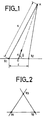
- Two neighboring bright bands have asymptotic directions defined by half-angle cones at the vertex ⁇ 1 and ⁇ 2 such that:
- the interfringe becomes very large because of the small value of sin 0; for these directions, the interfringe is greater than the width of the beam common to the 2 radars, it may be that a phase combination 0.0 or 0.1 (as defined below) corresponds to a dark fringe but in this the other combination corresponds to a bright fringe. There are also cases (dependent on the initial phase shift 1 , 2 ) for which the combinations 0.0 and 0.1 both correspond to intermediate values for the intensity of the fringes.
- phase relationships between the radar transmitters in order to shift the system of interference fringes between the radars.
- the purpose of this is to make the shiny fringes scan in steps the directions of the space located inside the beam common to the radars.
- This phase modification is made either from impulse to impulse or from burst to burst when the radars perform a signal processing which uses coherence techniques (coherent integration, Doppler filtering, etc.).
- the simplest case is that where there are only 2 radars; we can then modify the phase relationship between the 2 transmitters only once, going from ⁇ to ⁇ + ⁇ ; this allows the network of bright fringes and the network of dark fringes to be permuted; in this way, a coarse scan of the directions of space located inside the beam common to the two radars is created. If we want to improve the smoothness of the scan, we will go from ⁇ to ⁇ + 2 ⁇ 3 then to ⁇ + 4 ⁇ 3. But this will require 3 successive transmissions (or 3 bursts).
- the coarse scanning of the directions of space located inside the beam common to the 3 radars corresponds to 4 successive transmissions (or 4 bursts) defined as follows: either ⁇ 12 and ⁇ 13 the respective phase shifts between the transmitters 1 and 2, then 1 and 3 during the first pulse (or the first burst).
- the first column on the left corresponds to radar n ° 1; the second column corresponds to radar 2; the third column on radar 3.
- the number 0 placed in the 2nd column indicates that the phase relationship between the first 2 radars is kept constant, its (any) value is called ⁇ 12 ; the number 1 placed in the 2nd column indicates that the previous value goes from ⁇ 12 to ⁇ 12 + n.
- the third column indicates the phase difference between radar no. 3 and radar 1; the number 0 indicates that the phase difference between the 2 radars is kept constant at its initial value (any) ⁇ 13 ; the number 1 indicates that the phase shift goes from the value ⁇ 13 to ⁇ 13 + n.
- the presence of a 0 indicates that the phase of the i-th radar is kept constant (equal to any ⁇ 1, i ), the presence of a 1 indicates that ⁇ 1 , i is replaced by ⁇ 1, i + 2 ⁇ 3 the presence of a 2 indicates that ⁇ 1, i is replaced by ⁇ 1, i + 4 ⁇ 3.
- three radars R1, R2, R3 are provided which, instead of being aligned, are placed at the vertices of a triangle.
- this triangle can be equilateral.
- the search and tracking volume is then preferably centered on the normal to the plane of the triangle which passes through the orthocenter of the triangle.
- the interference system between R, and R 2 is a hyperboloid network of revolution around the line R I R 2
- the interference system between R, and R 3 is a hyperboloid network of revolution around the line R l R 3 .
- the arrangement in the preceding triangle is combined with aligned arrangements.
- five radars R1 to R5 are arranged at the vertices of two equilateral triangles having in common an angia at the vertex, the angle R1 for example.
- the radars R1, R3, R5 are therefore aligned as well as the radars R1, R2 and R4.
- the reception sets are supposed to have two by two equal transmission times and equal phase shifts between their inputs and their corresponding outputs as defined for the comparison of radars two by two.
- the measurement of the phase difference between the transmissions can be made according to Figure 5 where there are two radars 1 and 2 each comprising a transmitter (E1, E2), a receiver (REC1, REC2), a duplexer (D1, D2) connecting the transmitter and the receiver to an antenna (A1, A2).
- Each radar also has, according to the invention, in the reception chain, a phase shifter (DEPH1, DEPH2) receiving the preamplified signal from the amplifier (REC1, REC2) and transmitting it to the amplifier (REC'1, REC '2) after introduction of a controllable phase shift.
- the two radars are coupled by two directional couplers (CP1, CP2) to a single G waveguide.
- a first phase shift measurement system S1 with two inputs e1 and e'1 coupled to the waveguide G by two directional couplers CM1 and CM'1 suitably oriented.
- a second phase shift measurement system S2 has two inputs e2 and e'2 coupled, by directional couplers (CM2 and CM'2) suitably oriented, to the waveguide G.
- CM2 and CM'2 directional couplers
- the electrical length of the track connecting the directional couplers CP1 and CM1 is equal to that of the track connecting the directional couplers CP2 and CM2.
- the CM1-CM'1 link is identical to the CM2-CM'2 link.
- the electrical length of the channel connecting the directional coupler CP1 to the output of the receiver REC'1 is equal to that of the channel connecting the coupler CP2 to the output of the receiver REC'2 and this when the two phase shifters DEPH 1 and DEPH 2 are in the zero phase shift position.
- phase measurement systems S1, S2 make it possible to measure the phase differences of the signals on transmission from the two radars 1 and 2.
- the results of these measurements are transmitted to a difference and control circuit UC.
- These circuits make it possible to obtain the value of the phase difference 02 - 01 of the signals on transmission. More precisely, they make it possible to obtain the value 2 (0 2 - 0 1 ).
- the UC circuits control the DEPH1 and DEPH2 phase shifters. A differential phase shift is thus introduced as will be described below.
- the emission signal from each of the radars is sent to the other via a single guide G where the two emission signals propagate in opposite directions.
- These transmission signals are taken from radars 1 and 2 by the respective directional couplers CP1 and CP2 placed on the common channel for the transmission and reception of each radar.
- CP1 and CP2 a reference plane PR11 and PR21 respectively, these two reference planes being situated similarly inside the couplers. These two plans define the entrance to the reception channels of each speed camera.
- the system S1 measures the phase shift M1 between the signal of the local emission of the radar 1 and the signal of the emission of the radar 2 received via the guide G.
- the measurement system S2 measures the phase shift M2 between the signal from the local radar 2 emission and the signal from the radar 1 emission received via the guide G.
- the two measurement systems S1 and S2 take the signals subjected to the measurements via the respective couplers CM1, CM'1 and CM2, CM'2.
- the coupler CM1 supplies the local signal from radar 1 to input e1 of the measurement system S1.
- the coupler CM'1 supplies the input signal from transmitted radar 2 to input e'1 of the measurement system S1. by the guide G.
- the coupler CM2 supplies to the input e2 of the system S2, the local signal from the radar 2 and the coupler CM'2 supplies to the input e'2. the radar 1 emission signal transmitted by guide G.
- the two sets of couplers CP1, CM1, CM'1 on the one hand and CP2, CM2 and CM'2 on the other hand are identical as well as their internal connections. All directional couplers are fitted with a suitable load in the fourth channel in accordance with good practice.
- ⁇ ' 2 being the phase of the radar signal 2 received by the guide G.
- 0 1 and 0 2 represent, to the same constant constant, the emission phases respectively in the reference planes PR1 and PR2.
- a y representing the phase shift due to the waveguide G.
- the phase difference between the emissions from radars 1 and 2 in the reference planes PR1 and PR2 has been measured without having to know the length of the guide G.
- the radar whose emission is in phase advance will receive a signal in phase delay. To phase the 2 signals received by radars 1 and 2, it is therefore necessary to give a phase advance to the receiver corresponding to the transmission in phase advance.
- FIG. 5 represents the phase shifters DEPH1 and DEPH2 inserted between two receivers REC1, REC'1 for one of the phase shifters and REC2, REC'2 for the other phase shifter.
- these pairs of receivers REC1 - REC'1 and REC2 - REC'2 each form a single organ, a phase shifter (DEPH1, DEPH2) being placed inside each organ.
- phase shifters make it possible to compensate for the transmission phase shift, measured as described above, by a phase shift at reception.
- a difference calculation and control circuit UC makes it possible as a function of the measurement results M1 and M2 carried out by the measurement systems S1 and S2 to effect the difference M1 and M2 and to control the phase shifters DEPH1 and DEPH2 accordingly.
- the phase shift measurement system according to the invention may include a number n of radars.
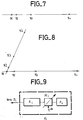
- FIG. 6 represents a system with four radars.
- the measurement of the phase shifts on transmission is made by separate comparisons which all take radar 1 as a reference and use guides G2, G3, G4 respectively to propagate the signals to be compared in both directions.
- the coupling of G2, G3, G4 is made respectively to radar 1 by the couplers CP 1.2, CP 1.3 and CP 1.4.
- the respective couplings to radars 2, 3 and 4 are made by couplers CP2, CP3 and CP4.
- the homologous paths of a pair of radars are provided with equal lengths.
- each waveguide G2, G3, G4 are coupled two phase-shift measurement systems similar to the systems S1 and S2 of FIG. 5.
- phase shift measurement system S 1.3 by couplers CM 1.3 and CM '1.3 and, on the other hand, a phase shift measurement system S3 by CM3 and CM'3 couplers.
- the two phase-shift measurement systems associated with the same waveguide supply their measurement results to a difference and control circuit not shown in FIG. 6 and make it possible to control the phase shifters of the radars associated with this waveguide.
- FIG. 9 indicates the way of introducing the phase shifts ⁇ or and 4f into the transmitters E2, E3, ... etc. with respect to the transmitter E1.
- the transmitters are generally terminated by a power amplifier tube A so that it is preferable to introduce the above phase shifts at low level at the input of the power amplifier by a controlled phase shift DE at the output of the pilot Pi.
- each Pi pilot has its own frequency reference (for example, an atomic clock) such that its high stability prevents any frequency sliding during the duration of the transmissions or bursts which must be made at the same frequency c that is to say during the 2P- 1 or 3 pl successive transmissions or gusts which ensure the scanning in steps of the space inside the beam common to the radars.
- frequency reference for example, an atomic clock
Landscapes
- Engineering & Computer Science (AREA)
- Radar, Positioning & Navigation (AREA)
- Remote Sensing (AREA)
- Computer Networks & Wireless Communication (AREA)
- Physics & Mathematics (AREA)
- General Physics & Mathematics (AREA)
- Radar Systems Or Details Thereof (AREA)
Claims (11)
Applications Claiming Priority (2)
| Application Number | Priority Date | Filing Date | Title |
|---|---|---|---|
| FR8412134 | 1984-07-31 | ||
| FR8412134A FR2568686B1 (fr) | 1984-07-31 | 1984-07-31 | Systeme d'exploitation de plusieurs radars voisins |
Publications (2)
| Publication Number | Publication Date |
|---|---|
| EP0172094A1 EP0172094A1 (de) | 1986-02-19 |
| EP0172094B1 true EP0172094B1 (de) | 1989-07-12 |
Family
ID=9306669
Family Applications (1)
| Application Number | Title | Priority Date | Filing Date |
|---|---|---|---|
| EP85401544A Expired EP0172094B1 (de) | 1984-07-31 | 1985-07-26 | Betriebssystem für mehrere benachbarte Radargeräte |
Country Status (3)
| Country | Link |
|---|---|
| EP (1) | EP0172094B1 (de) |
| DE (1) | DE3571507D1 (de) |
| FR (1) | FR2568686B1 (de) |
Families Citing this family (2)
| Publication number | Priority date | Publication date | Assignee | Title |
|---|---|---|---|---|
| US6762711B1 (en) | 1999-01-07 | 2004-07-13 | Siemens Aktiengesellschaft | Method for detecting target objects and for determining their direction and the like for a radar device |
| GB2357918A (en) * | 1999-09-30 | 2001-07-04 | Alenia Marconi Systems Ltd | HF Radar Tx/Rx assembly |
Family Cites Families (1)
| Publication number | Priority date | Publication date | Assignee | Title |
|---|---|---|---|---|
| US3454944A (en) * | 1968-03-13 | 1969-07-08 | United Aircraft Corp | Wide-angle interferometer radar |
-
1984
- 1984-07-31 FR FR8412134A patent/FR2568686B1/fr not_active Expired
-
1985
- 1985-07-26 EP EP85401544A patent/EP0172094B1/de not_active Expired
- 1985-07-26 DE DE8585401544T patent/DE3571507D1/de not_active Expired
Non-Patent Citations (1)
| Title |
|---|
| M.I.Skolnik, Introduction to Radar Systems, Mac-Graw-Hill, Tokyo (JP), 1980, pp. 280-283 * |
Also Published As
| Publication number | Publication date |
|---|---|
| FR2568686B1 (fr) | 1986-12-05 |
| DE3571507D1 (en) | 1989-08-17 |
| EP0172094A1 (de) | 1986-02-19 |
| FR2568686A1 (fr) | 1986-02-07 |
Similar Documents
| Publication | Publication Date | Title |
|---|---|---|
| EP2312335B1 (de) | Radar mit großer Winkelpräzision, insbesondere für die Funktion der Erkennung und Vermeidung von Hindernissen | |
| EP0600799B1 (de) | Aktive Antenne mit variabler Polarisations-Synthese | |
| EP2831615B1 (de) | Vorrichtung für aktive und passive elektromagnetische detektion mit geringer wahrscheinlichkeit von unterbrechungen | |
| EP0143497B1 (de) | Mit stetigen frequenzmodulierten Wellen arbeitendes Monopulsradargerät mit Achsenstabilisierung | |
| EP3819670A1 (de) | Verarbeitungsverfahren für kohärenten mimo-radar, der ddma-wellenformen verarbeitet | |
| FR2498336A1 (fr) | Dispositif de transmission d'ondes electromagnetiques en polarisation lineaire | |
| FR2948774A1 (fr) | Radar de detection de cibles aeriennes equipant un aeronef notamment pour l'evitement d'obstacles en vol | |
| WO1992019985A1 (fr) | Systeme de mesure de distances a echo avec dispositif de calibration | |
| EP0172094B1 (de) | Betriebssystem für mehrere benachbarte Radargeräte | |
| WO2010136461A1 (fr) | Télémètre absolu hyperfréquence de haute précision à dispositif de réflexion multi-etat | |
| EP3667357B1 (de) | Verfahren zur störung der von einem radar gesendeten elektronischen signatur, und entsprechend angepasste sende-/empfangsvorrichtung für die umsetzung dieses verfahrens | |
| WO2022073727A1 (fr) | Radar doppler a balayage electronique ambigu | |
| EP2822198B1 (de) | Verfahren und Vorrichtung zur Messung der Gruppenlaufzeit einer Antenne | |
| EP0613019B1 (de) | Abweichungsantenne für Monopulsradar | |
| EP1522871B1 (de) | Radar mit synthetischen Peilkanälen | |
| BE1032131B1 (fr) | Un système radar de surveillance des déformations à ouverture réelle basé sur PMCW-MIMO | |
| EP0163346A1 (de) | Mit Abstands- und Winkelmessung arbeitendes Endleitungs- oder Ortungszurückstellungssystem für ein Fahrzeug | |
| EP0624804A1 (de) | Zielverfolgungssystem zur Schätzung des Ausrichtungsfehlers einer HF-Antenne | |
| FR2965632A1 (fr) | Telemetre hyperfrequence a commutation de retards | |
| EP1233282A1 (de) | Vorrichtung mit verteilten Sende- und Empfangsantennen, insbesondere für Radar mit synthetischer Emission and Strahlbildung | |
| FR3134458A1 (fr) | Système de positionnement à segments de câble rayonnant | |
| EP4560943A1 (de) | Verbesserte gruppenantenne zur sende- und/oder empfangskalibrierung; sende- und/oder empfangskalibrierungsanordnungen | |
| FR2965634A1 (fr) | Telemetre hyperfrequence a diversite de polarisation | |
| FR2648917A1 (fr) | Dispositif radar destine a detecter des cibles a courte distance | |
| FR2749399A2 (fr) | Recepteur interferometrique a commande de gain generalise |
Legal Events
| Date | Code | Title | Description |
|---|---|---|---|
| PUAI | Public reference made under article 153(3) epc to a published international application that has entered the european phase |
Free format text: ORIGINAL CODE: 0009012 |
|
| AK | Designated contracting states |
Designated state(s): DE GB IT NL |
|
| 17P | Request for examination filed |
Effective date: 19860630 |
|
| 17Q | First examination report despatched |
Effective date: 19880210 |
|
| RAP3 | Party data changed (applicant data changed or rights of an application transferred) |
Owner name: THOMSON-CSF |
|
| GRAA | (expected) grant |
Free format text: ORIGINAL CODE: 0009210 |
|
| AK | Designated contracting states |
Kind code of ref document: B1 Designated state(s): DE GB IT NL |
|
| ITTA | It: last paid annual fee | ||
| PGFP | Annual fee paid to national office [announced via postgrant information from national office to epo] |
Ref country code: NL Payment date: 19890731 Year of fee payment: 5 Ref country code: GB Payment date: 19890731 Year of fee payment: 5 |
|
| ITF | It: translation for a ep patent filed | ||
| REF | Corresponds to: |
Ref document number: 3571507 Country of ref document: DE Date of ref document: 19890817 |
|
| PGFP | Annual fee paid to national office [announced via postgrant information from national office to epo] |
Ref country code: DE Payment date: 19890823 Year of fee payment: 5 |
|
| GBT | Gb: translation of ep patent filed (gb section 77(6)(a)/1977) | ||
| PLBE | No opposition filed within time limit |
Free format text: ORIGINAL CODE: 0009261 |
|
| STAA | Information on the status of an ep patent application or granted ep patent |
Free format text: STATUS: NO OPPOSITION FILED WITHIN TIME LIMIT |
|
| 26N | No opposition filed | ||
| PG25 | Lapsed in a contracting state [announced via postgrant information from national office to epo] |
Ref country code: GB Effective date: 19900726 |
|
| PG25 | Lapsed in a contracting state [announced via postgrant information from national office to epo] |
Ref country code: NL Effective date: 19910201 |
|
| NLV4 | Nl: lapsed or anulled due to non-payment of the annual fee | ||
| GBPC | Gb: european patent ceased through non-payment of renewal fee | ||
| PG25 | Lapsed in a contracting state [announced via postgrant information from national office to epo] |
Ref country code: DE Effective date: 19910403 |